High gain directly indicates how much an amplifier multiplies the power of an input signal, directly dictating overall system reach. When you are operating in remote areas, you often deal with incredibly weak signals. These fading transmissions lead to lost data, dropped communications, and compromised operations. By integrating high-quality RF Amplifiers, you instantly boost these faint signals to reliable levels, ensuring continuous and clear data transmission. This fundamental enhancement resolves the pain of dropped links completely.
What Exactly Is High Gain in RF Amplifiers?
High gain refers to the substantial multiplication factor applied to an input signal’s power. By utilizing robust RF Amplifiers, you can achieve the required signal amplification for long-distance transmissions. This multiplier is critical for maintaining network integrity. Achieving this effectively requires precise engineering.
How Do You Measure It?
You typically measure gain in decibels (dB), comparing output power to input power. Here is the deal: understanding this measurement allows you to calibrate your systems accurately. Without precise measurements, your signal could easily become distorted or too weak.
- Measure the input signal strength.
- Measure the output signal strength.
- Calculate the logarithmic ratio.
When you follow these steps, you maintain control over your signal quality.
Why Does It Matter?
It matters because it determines the operational range of your communication network. Now, consider this: if your gain is too low, the signal simply will not reach its destination. It directly influences your hardware choices and power budget.
- Impacts transmission range.
- Dictates power supply needs.
- Influences antenna choice.
Key Takeaway: High gain is essential for extending your communication range and preventing signal loss over vast distances.
| Metric | Low Gain Impact | High Gain Impact |
| Range | Short distance | Long distance |
| Signal Clarity | Prone to fading | Strong and clear |
Analyzing these metrics shows that higher gain strictly correlates with improved distance and robust signal integrity.
How Does High Gain Affect RF Amplifiers Signal Quality?
High gain significantly amplifies the signal, but it simultaneously amplifies any existing background noise. When using RF Amplifiers, you must carefully balance the power boost against potential signal degradation. Pushing the gain too high without proper filtering degrades the overall clarity. Proper design mitigates these unwanted effects.
Will It Cause Distortion?
Yes, excessive amplification often leads to harmonic distortion if not properly managed. But wait, there’s more: even the cleanest signals can degrade if pushed beyond the linear region. You need to monitor your output continuously to prevent this.
- Harmonics can interfere with adjacent channels.
- Intermodulation limits data throughput.
- Clipping destroys the signal waveform.
You must stay within the operational limits to avoid these issues.
Can I Prevent Noise?
You can prevent noise by utilizing low-noise components at the input stage. Let’s dive in: focusing on the noise figure of your initial stage dictates the quality of your entire chain. Adding filters also removes out-of-band interference effectively.
- Use cryogenic cooling where possible.
- Install sharp bandpass filters.
- Select low-noise transistors.
Key Takeaway: Implementing a low-noise first stage ensures that subsequent high gain boosts the signal, not the noise.
| Noise Source | Prevention Method | Effectiveness |
| Thermal Noise | Low-noise first stage | Very High |
| Interference | Bandpass filters | High |
Implementing bandpass filters efficiently reduces out-of-band interference, allowing the amplifier to process cleaner signals.
What Are Common Uses for High Gain RF Amplifiers?
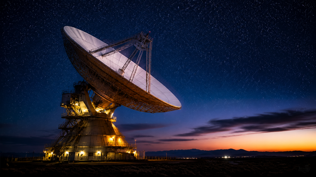
Common uses include satellite communications, radar tracking systems, and deep-space telemetry. Within these fields, specialized RF Amplifiers provide the massive power jumps required to transmit data across the atmosphere. You will find them wherever long-distance wireless links are established. They form the backbone of modern global connectivity.
Are They Used in Radar?
Radar systems heavily rely on extreme gain to detect tiny reflections from distant objects. Here is the kicker: without massive amplification, the return pulse would be indistinguishable from background static. You need this power to track fast-moving targets accurately.
- Pulse amplification requires fast switching.
- High peak power is essential for range.
- Low noise figures help detect stealth objects.
How About Satcom?
Satellite communications require immense gain to overcome path loss through space. Listen to this: when transmitting to a geostationary satellite, your signal travels over 22,000 miles. You must have a robust amplifier to make this journey possible.
- Overcomes atmospheric absorption.
- Compensates for free-space path loss.
- Drives large parabolic antennas.
Key Takeaway: High gain is absolutely non-negotiable for overcoming the extreme path loss inherent in space communications.
| Application | Typical Gain Needed | Primary Challenge |
| Radar | 40 dB – 60 dB | Fast pulse switching |
| Satcom | 50 dB – 70 dB | Massive path loss |
Comparing these applications reveals that Satcom demands the highest sustained gain to bridge orbital distances.
Why Do RF Amplifiers Struggle With Saturation?
They struggle with saturation because physical components have an absolute maximum power output limit. As RF Amplifiers reach their maximum voltage swing, they can no longer multiply the signal proportionally. This physical ceiling causes the peaks of your signal to flatten. Understanding this limit helps you design better networks.
What Is the P1dB Point?
The P1dB point indicates where the amplifier’s actual output drops 1 dB below its ideal linear output. It boils down to this: this metric is your primary warning sign before heavy distortion occurs. You should always operate your system well below this threshold.
- It defines the linear operating range.
- Operating near it causes signal clipping.
- It helps determine the required back-off.
How Do You Avoid Clipping?
You avoid clipping by implementing proper power back-off strategies during the design phase. Think about it: sacrificing a bit of maximum power output guarantees a much cleaner transmission. This ensures your data packets remain intact and readable.
- Calculate peak-to-average power ratio.
- Apply necessary dB back-off.
- Monitor output constantly.
Key Takeaway: Always operate with a sufficient power back-off margin to keep your signals clean and distortion-free.
| Metric | Meaning | Impact on Signal |
| Linear Region | Gain is constant | Clean output |
| Saturation | Gain decreases | Severe clipping |
Operating within the linear region ensures optimal signal fidelity and prevents catastrophic data loss.
How Can You Manage Heat in High Gain RF Amplifiers?
You manage heat through advanced thermal dissipation techniques like specialized heat sinks and active cooling. High-power RF Amplifiers generate immense thermal energy due to efficiency losses during the amplification process. If you do not extract this heat quickly, the internal components will fail. Effective cooling extends the lifespan of your hardware.
Is Liquid Cooling Best?
Liquid cooling provides superior thermal transfer rates compared to traditional air cooling. Truth be told: for multi-kilowatt systems, pumping liquid through cold plates is the only viable option. It allows you to maintain stable operating temperatures under heavy loads.
- Liquid absorbs heat faster than air.
- It allows for more compact amplifier designs.
- Maintenance requires monitoring coolant levels.
What About Heat Sinks?
Passive and active heat sinks work perfectly for lower power applications. The bottom line is this: a well-machined aluminum block with high-velocity fans can handle surprisingly high thermal loads. You must ensure proper airflow to maximize their efficiency.
- Use high-grade aluminum or copper.
- Apply premium thermal paste.
- Ensure unobstructed case ventilation.
Key Takeaway: Selecting the appropriate cooling mechanism is critical to prevent thermal runaway and permanent hardware damage.
| Cooling Type | Best For | Maintenance Level |
| Air / Heat Sink | Medium power | Low |
| Liquid Cooling | High power | High |
Evaluating these cooling methods indicates that liquid systems are necessary as power and gain demands increase.
What Is the Trade-Off With Bandwidth in RF Amplifiers?
The trade-off dictates that as you increase the gain, your usable bandwidth generally decreases. Designing RF Amplifiers forces engineers to balance how wide a frequency range they can cover versus how much power they can boost. You cannot usually achieve maximum gain across a massive frequency spectrum simultaneously. This physical limitation requires careful system planning.
Can You Have Both?
Achieving both high gain and wide bandwidth requires complex, multi-stage matching networks. Let me explain: specialized transistor technologies like Gallium Nitride (GaN) make this easier today than in the past. However, you will still face compromises in efficiency.
- GaN transistors offer wider bandwidths.
- Feedback circuits can flatten the gain.
- Matching networks become highly complex.
How Do You Balance Them?
You balance them by defining your exact system requirements before selecting components. Picture this: if your application only needs a narrow band, you can maximize your gain easily. You should never pay for bandwidth you do not intend to use.
- Specify exact frequency limits.
- Avoid over-engineering the bandwidth.
- Focus on targeted impedance matching.
Key Takeaway: Prioritize your exact frequency requirements to optimize the gain without wasting engineering resources on unnecessary bandwidth.
| Specification | High Gain Focus | Wide Bandwidth Focus |
| Matching Network | Narrowly tuned | Broadly tuned |
| Efficiency | Generally higher | Generally lower |
Analyzing this trade-off shows that focusing on a narrow frequency band yields a much higher overall efficiency.
How Does Linearity Impact High Gain RF Amplifiers?
Linearity ensures that the amplifier multiplies the signal evenly without adding new, unwanted frequencies. In complex digital modulations, RF Amplifiers must maintain strict linearity to preserve the data encoded in the signal. If the output does not perfectly mirror the input shape, your receiver will drop data. Good linearity is the hallmark of premium hardware.
Why Is Linearity Crucial?
Linearity is crucial because modern communication standards use amplitude modulations that are highly sensitive to distortion. Here is what you need to know: if you alter the amplitude incorrectly, the decoded data becomes corrupted. You must preserve the exact waveform shape.
- Prevents data corruption in complex signals.
- Reduces adjacent channel interference.
- Maintains regulatory compliance for emissions.
What Happens If It Fails?
If linearity fails, your system generates intermodulation products that jam nearby frequencies. Check this out: you could inadvertently block other users on adjacent channels, leading to severe regulatory fines. You lose both data integrity and legal compliance.
- Causes adjacent channel leakage.
- Drops critical digital packets.
- Violates FCC emission standards.
Key Takeaway: Maintaining strict linearity is critical for data preservation and avoiding interference with neighboring communication channels.
| Modulation | Linearity Requirement | Distortion Impact |
| QPSK | Moderate | Low data loss |
| 256-QAM | Extremely High | Severe data loss |
Reviewing these modulation schemes highlights that complex data formats demand absolute linear amplification.
What Role Do Cascaded RF Amplifiers Play?
Cascaded systems connect multiple amplifier stages in series to achieve a massive total gain. When a single stage cannot provide enough boost, RF Amplifiers are daisy-chained to multiply the power incrementally. You use this technique to reach gain levels impossible with a single transistor. It requires careful impedance matching between each stage.
How Does Friis Formula Work?
The Friis formula proves that the first stage dictates the noise performance of the entire cascaded chain. You cannot ignore this: if your first stage is noisy, every subsequent stage will just amplify that noise. You must put your best component first.
- Stage one sets the baseline noise.
- Later stages contribute less to overall noise.
- High gain in stage one is highly beneficial.
Can It Boost Total Gain?
Cascading multiple stages mathematically adds their individual decibel gains together for massive output. Get ready for this: linking three 10 dB stages gives you a massive 30 dB total boost. You can build immensely powerful systems using small, manageable blocks.
- Calculate total gain by addition.
- Ensure inter-stage impedance matching.
- Use isolators between stages.
Key Takeaway: Cascading allows you to achieve extreme amplification, provided you strictly manage the noise figure of the very first stage.
| Stage Position | Gain Contribution | Noise Contribution |
| First Stage | High priority | Critical impact |
| Final Stage | High priority | Minimal impact |
This breakdown confirms that the initial stage is the most critical for preserving signal clarity in cascaded designs.
How Do You Choose the Right High Gain RF Amplifiers?
You choose the right equipment by carefully evaluating your specific frequency, power, and environmental requirements. Selecting RF Amplifiers involves matching the manufacturer’s datasheets directly to your system’s operational needs. You must look beyond just the maximum gain figure. A holistic approach ensures long-term reliability.
What Specs Are Key?
The most critical specs are frequency range, P1dB, noise figure, and thermal limits. Let’s look closely: ignoring the thermal limits will guarantee a spectacular hardware failure in the field. You have to consider how the unit behaves under extreme stress.
- Frequency range dictates compatibility.
- P1dB shows your linear power limit.
- Efficiency ratings impact cooling costs.
How to Evaluate Costs?
You evaluate costs by looking at the total cost of ownership, including cooling and power consumption. You might be wondering: is a cheaper amplifier worth it if it doubles your electricity bill? Often, investing in high-efficiency hardware saves you money long-term.
- Calculate annual power consumption.
- Factor in specialized cooling costs.
- Assess expected lifespan and maintenance.
Key Takeaway: Always evaluate an amplifier based on its total operational costs and its ability to withstand your specific environmental stresses.
| Cost Factor | Upfront Expense | Long-Term Expense |
| Hardware | High | Low |
| Cooling/Power | Moderate | Very High |
Analyzing total ownership costs reveals that power and cooling expenses often overshadow the initial hardware investment.
Can High Gain RF Amplifiers Ruin Your System?
Yes, if improperly matched or isolated, they can cause catastrophic oscillations that destroy sensitive components. Without proper safeguards, RF Amplifiers can feed energy back into themselves, turning into powerful, uncontrolled oscillators. You must implement strict isolation and shielding protocols. Poor integration will fry your transmission lines.
What Is Oscillation?
Oscillation occurs when an amplified signal leaks back into the input and is continuously re-amplified. Here is the danger: this infinite loop generates massive power spikes that can literally melt internal traces. You must physically and electrically isolate the input from the output.
- Caused by poor grounding.
- Triggered by inadequate shielding.
- Results in hardware destruction.
How to Ensure Stability?
You ensure stability by utilizing isolators, proper grounding planes, and careful PCB layout. You simply must remember this: unconditional stability means the amplifier will not oscillate under any load condition. You should always verify stability across all frequencies.
- Install output isolators.
- Design solid ground planes.
- Utilize decoupling capacitors.
Key Takeaway: Implementing rigorous shielding and utilizing isolators guarantees that your high-power system remains stable and safe.
| Stability Threat | Prevention Technique | Protection Level |
| Reflected Power | Use RF Isolators | Maximum |
| Signal Leakage | Add metal shielding | High |
Utilizing RF isolators effectively prevents reflected power from causing destructive feedback loops within the system.
Conclusion
Navigating the complexities of signal multiplication, noise control, and thermal management can be daunting. In this guide, we solved the primary challenges of selecting and optimizing hardware to prevent distortion and ensure maximum range. We can provide you with fully integrated, rigorously tested power solutions tailored exactly to your frequency and linearity requirements. If you are ready to upgrade your communication networks with uncompromising quality, please contact us today to speak with our engineering team. At our core, we believe that reliable communication drives human progress, and we engineer every product to deliver absolute perfection under pressure.
FAQ
Can I use a single high gain amplifier instead of multiple smaller ones?
It depends. While a single unit saves space, using multiple cascaded stages often provides better noise control and thermal management for extreme power needs.
What’s the best way to prevent an amplifier from overheating?
The best way is active cooling. Utilizing liquid cold plates or forced-air heat sinks actively removes the thermal energy generated during the power conversion process.
How do I know if my amplifier is saturated?
Yes, you can easily tell by checking the output waveform. If the peaks of your signal are flattened or your data error rate suddenly spikes, you have hit the saturation point.
Can I run my amplifier at its absolute maximum rated power?
No. You should always implement a power back-off margin to ensure the device operates within its linear region, preventing clipping and distortion.
What’s the best transistor material for wideband applications?
It is Gallium Nitride (GaN). This material naturally supports wider frequency bandwidths and handles higher thermal loads compared to traditional silicon-based components.