
The uses and benefits of omnidirectional antenna types center on providing seamless, 360-degree wireless coverage without requiring precise physical alignment between devices. When establishing a modern wireless network, you often face the frustrating challenge of dead zones and dropped signals caused by directional alignment issues. These connection drops can halt warehouse automation or interrupt critical public safety communications, costing your organization valuable time and money. Selecting the right Omnidirectional Antenna provides a robust solution by broadcasting and receiving signals in all horizontal directions to eliminate alignment-induced failures.
Match omnidirectional antenna coverage to the RF chain
CorelixRF can review coverage pattern, polarization, gain, mounting, connector, amplifier compatibility and front-end integration before moving from antenna selection to RFQ.
Why is 360-degree signal coverage critical?
Achieving uniform signal distribution in every direction is essential for dynamic environments where users or endpoints are constantly in motion. If your equipment moves or if you have multiple devices scattered across a campus, point-to-point directional systems will fail.
Think about it:
How can you maintain a link when the receiver is always moving? This is exactly where a multi-directional pattern shines.
By deploying these omnidirectional systems, you secure key advantages across your operational layout.
- Zero-alignment overhead: You skip the complex alignment math during installation.
- Multi-point connectivity: A single central node serves dozens of mobile clients simultaneously.
- Resiliency: Obstacles are easily bypassed via multi-path reflections from surrounding walls.
These advantages ensure your infrastructure remains agile and responsive under shifting real-world conditions.
Key Takeaway: Utilizing a 360-degree radiation pattern eliminates the need for physical alignment, drastically lowering deployment costs and ensuring reliable connections for dynamic, mobile B2B assets.
How does an omnidirectional antenna operate?
An omnidirectional antenna operates by radiating radio frequency (RF) energy uniformly in the horizontal plane, shaping a donut-like (toroidal) pattern. This layout compresses vertical beamwidth to boost horizontal signal reach across your facility. When you apply RF power, the internal radiator elements excite a symmetrical electromagnetic wave. This process ensures that your Omnidirectional Antenna delivers equal power density to all surrounding receivers.
How does polarization shape the RF signal?
Polarization determines the physical orientation of the electric field vector as it propagates through space. Matching this polarization between your transmitter and receiver is critical to preventing severe signal loss.
But here is the catch:
If your receiving nodes are oriented vertically, a horizontally polarized wave will cause up to a 30 dB signal drop. To avoid these devastating losses, you must carefully select the correct polarization type for your environment.
- Vertical Polarization: Ideal for land mobile radio and vehicle setups.
- Horizontal Polarization: Excellent for reducing ground-reflection interference in fixed points.
- Circular Polarization: Perfect for overcoming multipath distortion in dense urban spaces.
Selecting the right match keeps your network operating at peak efficiency.
Key Takeaway: Aligning signal polarization with your operational environment prevents major signal attenuation and maximizes system throughput.
| Polarization Type | Primary Use Case | Signal Characteristic | Polarization Loss Risk |
|---|---|---|---|
| Vertical | Land Mobile, Vehicular | High penetration in open space | High if receiver tilts |
| Horizontal | Fixed Point-to-Point | Low ground-reflection pickup | High in dynamic mobile environments |
| Circular | Urban MIMO, Satellite | Excellent multipath rejection | Minimal during rotation |
This comparison highlights why choosing the correct polarization is the foundational first step to maximizing overall RF efficiency.
Why use a whip antenna for mobile RF setups?
You should use a whip antenna for mobile RF setups because its flexible, compact design provides rugged durability alongside consistent 360-degree coverage on moving platforms. This type of mobile Omnidirectional Antenna mounts easily to vehicles, handheld radios, or field equipment. It stands up to harsh mechanical shocks, making it perfect for your fleet management or utility trucks.
How do ground planes impact whip performance?
A whip antenna typically requires a metal ground plane to act as the second half of its dipole structure. Without this conductive surface, the radiation pattern deforms and your signal range shrinks rapidly.
Think about it:
Your vehicle’s metal roof is not just a mounting bracket; it is a vital part of the RF system.

When integrating a whip antenna, your ground plane options will directly dictate real-world efficiency.
- Magnetic Mounts: Use the vehicle body as a temporary ground plane without drilling holes.
- Thru-Hole Mounts: Provide the most stable electrical connection to the chassis.
- Ground-Plane Independent Whips: Feature internal designs for non-metal surfaces like fiberglass.
Using the right ground plane configuration ensures your signal remains strong and stable.
Key Takeaway: Utilizing a proper metal ground plane or selecting a ground-plane independent whip model ensures optimal gain and prevents pattern distortion in mobile installations.
| Whip Mount Type | Ground Plane Required | Ideal Application | Mechanical Stability |
|---|---|---|---|
| Magnetic | Yes (Metal Chassis) | Temporary Fleet Deployments | Moderate (Speed-dependent) |
| Thru-Hole | Yes (Metal Chassis) | Permanent Fleet, Heavy Duty | Excellent (Vibration-resistant) |
| Independent | No | Fiberglass Cabinets, Marine | Excellent (Self-contained) |
Refer to this matrix to match your vehicle’s physical material with the proper mounting design for uninterrupted mobile links.
What are the benefits of ceiling mount types?
Ceiling mount types provide the benefit of unobtrusive, aesthetic overhead coverage that distributes signals evenly downward throughout indoor spaces. By deploying this discrete Omnidirectional Antenna style, you can blanket offices, hospitals, or retail centers with high-capacity wireless connections. These low-profile designs blend seamlessly into acoustic tiles while keeping critical hardware safe from tampering.
Why are dome and profile designs preferred?
Dome and low-profile ceiling designs are preferred because they minimize visual impact while protecting the internal radiating elements from dust and accidental impacts. In commercial environments, maintaining clean aesthetics is just as important as signal quality.
And the best part?
These enclosures use RF-transparent plastics that prevent any signal degradation.

Selecting these specialized indoor form factors delivers multiple immediate benefits for your facility.
- Tamper Prevention: Keeps connections secure from unauthorized access.
- Clean Aesthetics: Matches modern architectural interiors perfectly.
- Broad Beam Downward: Ensures no indoor dead zones underneath the mounting point.
This makes them the standard choice for enterprise WLAN and indoor DAS networks.
Key Takeaway: Deploying low-profile ceiling-mount antennas secures indoor environments visually and physically while providing uniform downward signal distribution for high-density user zones.
| Ceiling Mount Design | Profile Height | Primary Environment | Aesthetic Rating |
|---|---|---|---|
| Low-Profile Dome | < 2 inches | Corporate Offices, Hospitals | Ultra-Discreet |
| Standard Dome | 2 – 4 inches | Warehouses, Supermarkets | Industrial-Clean |
| Suspended Mount | Adjustable | High-Ceiling Exhibition Halls | Utility-Focused |
Evaluating your ceiling height and aesthetic requirements will help you choose the ideal dome design for complete indoor coverage.
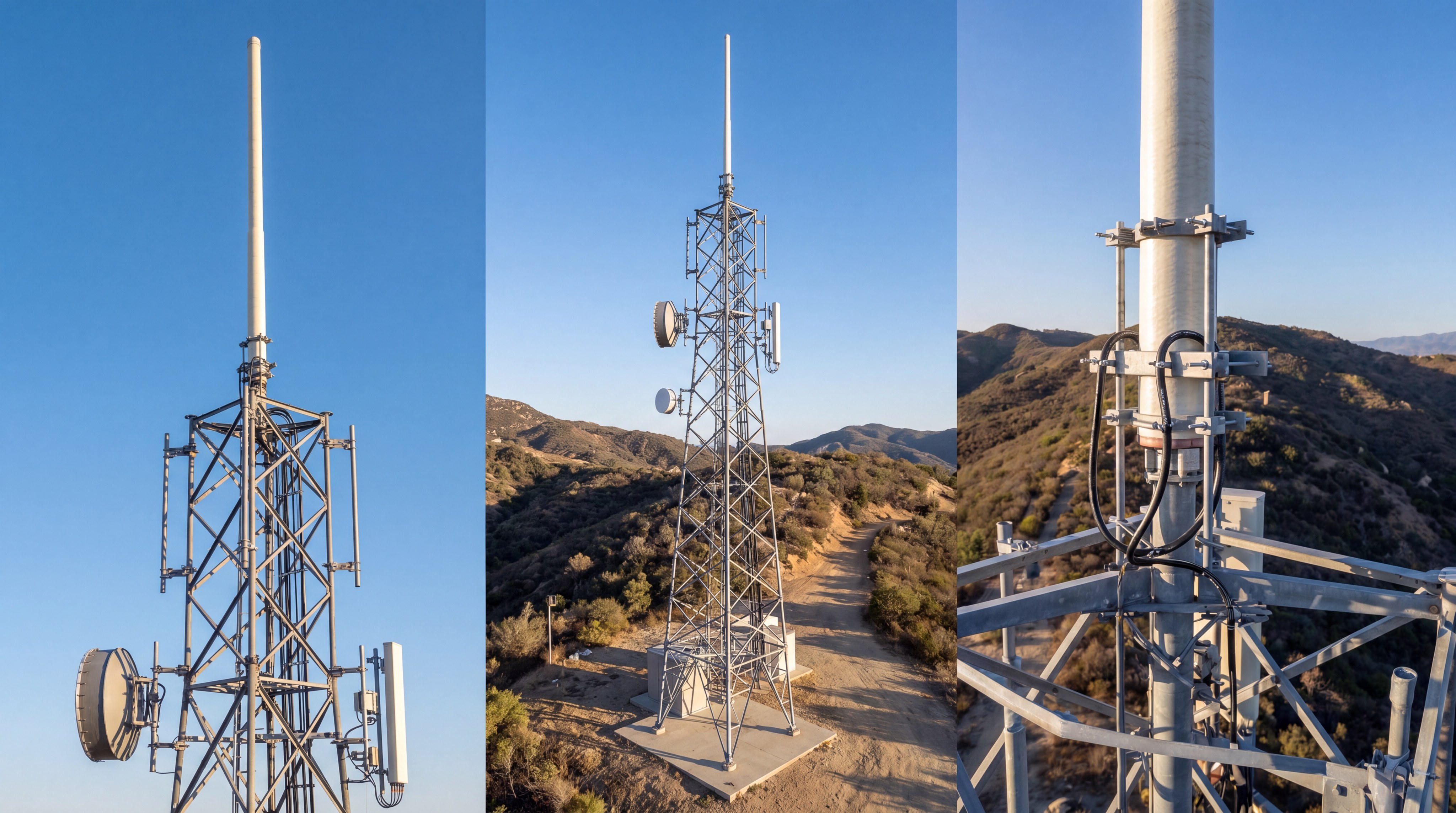
How do fiberglass collinear antennas perform?
Fiberglass collinear antennas perform exceptionally well in harsh outdoor environments, delivering high gain and long-range horizontal coverage for fixed stations. This rugged outdoor Omnidirectional Antenna stacks multiple radiating elements vertically inside a weather-proof fiberglass radome. By focusing energy toward the horizon, it allows you to establish reliable long-distance links to multiple remote terminals.
Why do collinear designs achieve higher gain?
Collinear designs achieve higher gain by stacking half-wave dipoles vertically to flatten the vertical RF beam and push energy further horizontally. This vertical stacking forces the RF signal outward like a thin, wide disc rather than a sphere.
But here is the catch:
As you increase the gain, the vertical beamwidth gets narrower, meaning target devices must lie within that flat plane.
Managing this gain-versus-beamwidth trade-off is critical when designing your outdoor base station infrastructure.
- High Gain (8-12 dBi): Ideal for flat terrain and extremely long-distance remote telemetry.
- Medium Gain (5-7 dBi): Perfect for rolling hills or suburban areas with moderate elevation changes.
- Low Gain (2-3 dBi): Best for mountainous terrain where signals must travel upward and downward.
Choosing the right dBi rating ensures your signal reaches every outlying node.
Key Takeaway: Specifying fiberglass collinear antennas with the correct gain level allows you to trade vertical beamwidth for dramatic increases in horizontal range, tailoring coverage to your terrain.
| Antenna Gain (dBi) | Vertical Beamwidth | Ideal Terrain | Max Effective Range |
|---|---|---|---|
| 3 dBi | ~60 degrees | Mountainous / Hilly | Short-to-Medium |
| 6 dBi | ~30 degrees | Rolling Hills / Suburban | Medium-to-Long |
| 10 dBi | ~8 degrees | Flat Plains / Desert | Long-Range / Base Station |
This data illustrates that higher gain is not always superior; matching the beamwidth to your local topography is key.
Why are MIMO omnidirectional designs growing?
MIMO omnidirectional designs are growing rapidly because they multiplex multiple spatial streams to drastically increase data speeds and link reliability in congested areas. Implementing this advanced Omnidirectional Antenna setup helps you overcome the multipath interference common in dense urban or industrial environments. Instead of fighting reflections, a MIMO system uses them to transmit more data simultaneously.
How does spatial diversity improve throughput?
Spatial diversity improves throughput by separating antenna elements physically or through polarization, allowing the RF system to process independent signal paths. When your system sends multiple signals over separate paths, it reduces the chance of total signal fading.
Think about it:
If one path is blocked by a passing truck, the other paths keep your data moving without packet loss. This multi-element design delivers massive operational benefits for modern high-bandwidth industrial networks.
- Higher Data Rates: Aggregates bandwidth across multiple RF chains.
- Reduced Packet Retransmissions: Improves real-time control system responsiveness.
- Dual-Polarization Support: Maximizes signal capture from random device orientations.
This ensures your automated guided vehicles (AGVs) or smart grids run without interruption.
Key Takeaway: Integrating MIMO omnidirectional architectures increases network capacity and reliability, making them indispensable for high-throughput, mission-critical industrial automation.
| MIMO Configuration | Element Count | Target Environment | Key Benefit |
|---|---|---|---|
| 2×2 MIMO | 2 Elements | Light Industrial, Fleet | Double throughput, simple install |
| 4×4 MIMO | 4 Elements | Heavy Industrial, High Density | Maximum multipath resilience |
| Cross-Polarized | 2 Elements (H/V) | Urban Canopy, Warehouses | Excellent polar diversity, compact |
Selecting the appropriate MIMO configuration helps you balance throughput requirements against the physical space available on your deployment mounts.
How do you optimize UHF amplifier integrations?
You optimize UHF amplifier integrations by choosing low-loss cabling and precisely matching the system impedance to prevent signal reflections between the amplifier and the antenna. Combining a high-performance UHF amplifier with a rugged outdoor Omnidirectional Antenna maximizes your signal range across challenging UHF bands. This integrated setup ensures that your broadcasted signals remain clear of distortion and reach every receiver in the field.
Why is impedance matching critical in UHF?
Impedance matching is critical in UHF systems because even minor mismatches can cause signal power to reflect back into your amplifier, risking hardware damage. This reflected power, measured as Voltage Standing Wave Ratio (VSWR), wastes valuable battery power and reduces your system’s output.
But here is the catch:
High VSWR doesn’t just lower efficiency; it can overheat your active components and lead to total system failure. To protect your equipment and optimize UHF performance, you must follow strict RF design practices.
- Use 50-Ohm Components: Ensure all connectors, cables, and ports match perfectly.
- Deploy Quality Coaxial Cables: Minimize signal loss over long outdoor runs.
- Implement Bandpass Filters: Prevent out-of-band noise from overloading your amplifier.
These actions guarantee that your power is transmitted into the air, not wasted as heat.
Key Takeaway: Maintaining strict impedance matching and using high-quality components protects your UHF amplifier investments and guarantees maximum RF power transmission to your omnidirectional system.
| VSWR Rating | Reflected Power (%) | System Health Status | Action Required |
|---|---|---|---|
| 1.1:1 – 1.3:1 | < 2% | Excellent (Optimal) | None – Perfect configuration |
| 1.5:1 – 1.8:1 | 4% – 8% | Acceptable | Monitor connections and weatherproofing |
| 2.0:1 or higher | > 11% | Dangerous (High Risk) | Immediately check for cable/antenna damage |
Reviewing your VSWR metrics allows you to catch connection issues early before they cause hardware damage or signal drops.
What challenges exist in multi-band systems?
Challenges in multi-band systems focus on managing severe inter-band interference, port-to-port isolation, and maintaining stable radiation patterns across widely separated frequencies. When you design a multi-band system using a single Omnidirectional Antenna, you must ensure that different signals do not distort one another. Leveraging advanced RF front-end platforms helps you filter and separate these frequencies before they reach your transmitter elements.
How do you achieve high isolation?
Achieving high isolation requires integrating physical separation within the antenna enclosure alongside high-rejection diplexers or triplexers. Without sufficient isolation, a high-power cellular signal can bleed into and desensitize your GPS receiver.
And the best part?
Modern filtering tech isolates these channels by over 30 dB without adding bulky hardware. Implementing high isolation in your multi-band setups ensures maximum performance across all frequencies.
- Internal Shielding: Blocks direct electromagnetic coupling between active elements.
- High-Performance Diplexers: Route frequencies cleanly to their designated ports.
- Active Isolation Circuits: Dynamically suppress interference in real-time.
This allows you to combine Wi-Fi, cellular, and GPS into a single compact node.
Key Takeaway: Utilizing advanced RF front-end platforms and filtering ensures high isolation, allowing you to combine multiple wireless protocols into a single, efficient multi-band antenna footprint.
| Isolation Method | Isolation Level (dB) | Size Impact | Key System Benefit |
|---|---|---|---|
| Cavity Diplexers | > 40 dB | Moderate-to-High | Maximum power handling, zero bleed |
| Ceramic Filters | 25 – 35 dB | Ultra-Compact | Ideal for mobile/IoT devices |
| Spatial Separation | 20 – 30 dB | Medium | Simple design, cost-effective |
This breakdown shows how different filtering and isolation methods allow you to balance size constraints against your isolation requirements.
How does custom RF engineering maximize yield?
Custom RF engineering maximizes yield by tailoring electrical and mechanical specifications directly to your unique environmental requirements, bypassing the performance limits of a generic standard platform. Relying on a mass-market Omnidirectional Antenna often results in compromised range or premature physical failure under harsh field conditions. By customizing your antenna design, you ensure optimal pattern coverage, extreme durability, and maximum data throughput.
Why choose custom over standard options?
Choosing custom engineering ensures your hardware is optimized for your exact frequency bands, mounting constraints, and structural needs. Standard off-the-shelf products often force you to accept compromises in gain, cable length, or housing durability.
Think about it:
Why limit your state-of-the-art wireless network with generic hardware when a tailored solution is readily available?
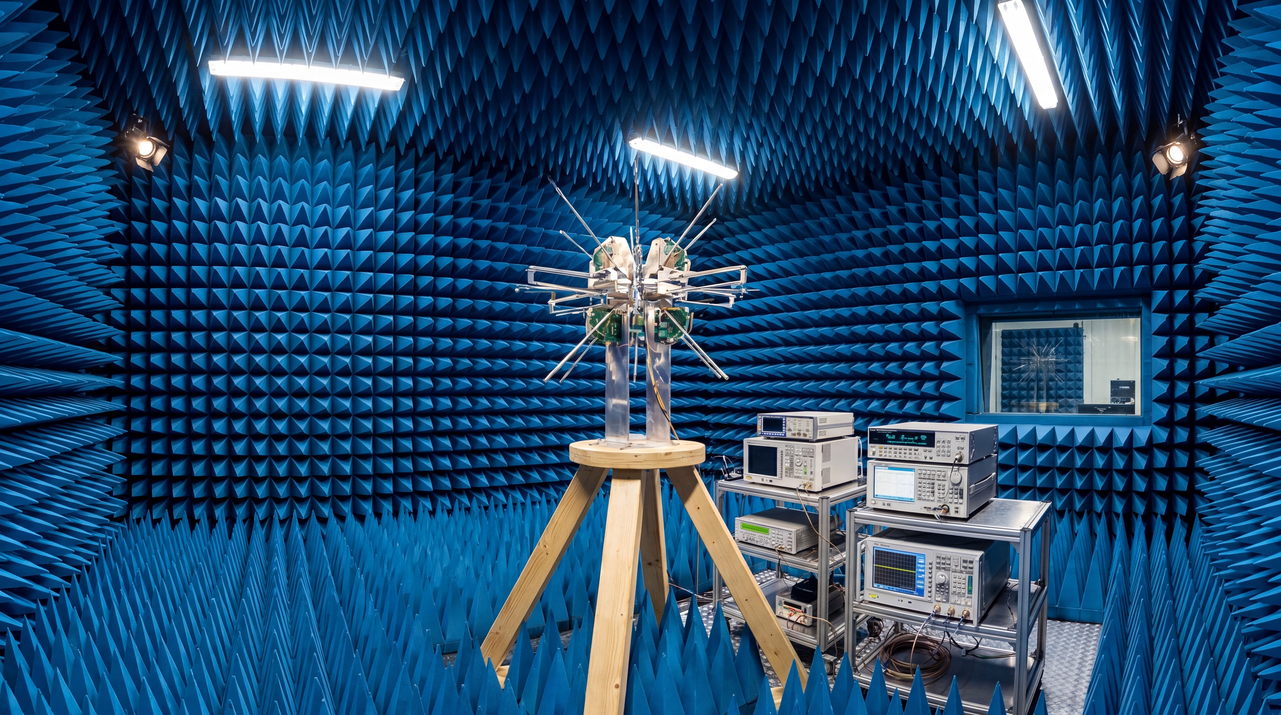
Partnering with Corelix, an elite RF engineering factory, equips you with the tailored manufacturing, precision tuning, and advanced testing to resolve signal issues. Our state-of-the-art facility transforms complex frequency challenges into robust physical solutions that guarantee your systems survive demanding environments. To unlock these benefits and elevate your next deployment, contact us today to discover how our expert custom engineering can power your long-term connection vision.
Key Takeaway: Partnering with a specialized RF engineering manufacturer for custom antenna designs eliminates compromises, delivering higher field reliability and superior network performance.
| Design Approach | Performance Optimization | Longevity in Harsh Climates | Total Cost of Ownership |
|---|---|---|---|
| Standard Platform | Moderate (Generic) | Variable | Higher due to replacement rates |
| Custom RF Engineering | Maximum (Tailored) | Ultra-High | Lower over long-term operations |
This comparative view highlights why choosing custom engineering delivers far greater return on investment for enterprise infrastructure projects.
What are the FAQs on omnidirectional systems?
Navigating the world of RF design requires understanding how an Omnidirectional Antenna performs under various conditions. When you are planning a deployment, you need fast, accurate answers to complex technical questions. The following frequently asked questions address the core performance features and installation choices you will encounter in the field.
- Can I use an omnidirectional antenna for long-range point-to-point links?
No, because point-to-point links require highly focused energy in a single direction to span extreme distances. While an omnidirectional design can broadcast to multiple nodes, it scatters signal power in 360 degrees, which reduces its maximum directional range. - What’s the best way to prevent outdoor water ingress into my coax cables?
Typically, applying self-amalgamating silicone tape around all RF connectors is the most effective defense against moisture. Water ingress will degrade signal performance quickly and can permanently damage your transmission lines. - How do I know if my antenna needs an external ground plane?
Typically, you can verify this by checking the product datasheet for the term “ground-plane independent.” If it is not listed, you must mount the antenna on a metal surface that measures at least a quarter-wavelength in diameter. - Can I mount an omnidirectional antenna horizontally to save physical space?
No, because mounting a vertically polarized antenna horizontally rotates the electric field, leading to severe polarization loss. This change will drastically reduce your coverage range and distort the intended donut-shaped radiation pattern. - What’s the best gain rating for an indoor warehouse deployment?
Typically, a low-to-medium gain antenna (2 dBi to 5 dBi) is best because it provides a wider vertical beamwidth. This wider beam easily reaches barcode scanners and mobile tablets operating at various heights beneath the ceiling.