An RF Amplifier is a specialized electronic device that increases the power of radio frequency signals, ensuring that your data reaches its destination across vast distances without falling into the noise floor. Without this critical boost, your transmission would succumb to natural attenuation, resulting in dropped connections, failed radar detection, and catastrophic system downtime in mission-critical environments. By integrating a high-performance RF Amplifier into your front-end, you transform weak waveforms into robust carriers capable of overcoming interference and long-range propagation losses.
What exactly is a high-frequency power booster?
A high-frequency power booster, commonly known as an RF Amplifier, is a component that adds gain to a signal within the kilohertz to gigahertz spectrum. These devices are the energy engines of wireless systems, taking a low-power input and scaling it to a level suitable for driving antennas or further processing stages.
Think about it:
If your signal lacks the necessary amplitude, the receiver simply cannot distinguish your data from the background electromagnetic environment. You must select hardware that provides sufficient gain while maintaining the integrity of the original modulation.
Is every amplifier designed the same way?
Not all boosters are created for the same purpose, as their design depends heavily on where they sit in the signal chain. You will typically encounter three primary categories:
- Low-Noise Amplifiers (LNAs): Situated at the receiver front-end to boost weak incoming signals.
- Power Amplifiers (PAs): Located at the transmitter end to provide the final wattage for transmission.
- Driver Stages: Used to provide intermediate gain between the source and the final power stage.
Why is signal preservation so important?
The truth is:
An RF Amplifier must do more than just make a signal “louder”; it must do so without introducing excessive distortion. If the phase or frequency components are shifted significantly, the complex data packets used in 5G or satellite links become unreadable.
Key Takeaway: The primary value of an RF Amplifier is its ability to provide measurable gain while preserving the phase and frequency characteristics of the input signal.
| Category | Primary Role | Key Focus |
|---|---|---|
| Receiver | Signal Sensitivity | Low Noise Figure |
| Transmitter | Transmission Range | High Output Power |
| Distribution | Signal Buffering | Flatness and Gain |
This data suggests that choosing the right category is the first step in ensuring your system meets its link budget requirements.
How does signal magnification work in modern systems?
Signal magnification in an RF Amplifier works by using a DC power source to modulate an active semiconductor device, thereby creating a higher-power replica of the input signal. This process is essentially a conversion of energy, where the transistor acts as a valve controlled by the small RF input to release larger amounts of DC energy into the output load.
Here is the deal:
To achieve this magnification, the hardware must be perfectly tuned to the operating frequency. If the internal matching networks are off by even a few megahertz, the efficiency drops and the device begins to generate excessive heat rather than signal power.
What are the steps of the magnification process?
The conversion from low-power input to high-power output follows a standard engineering sequence:
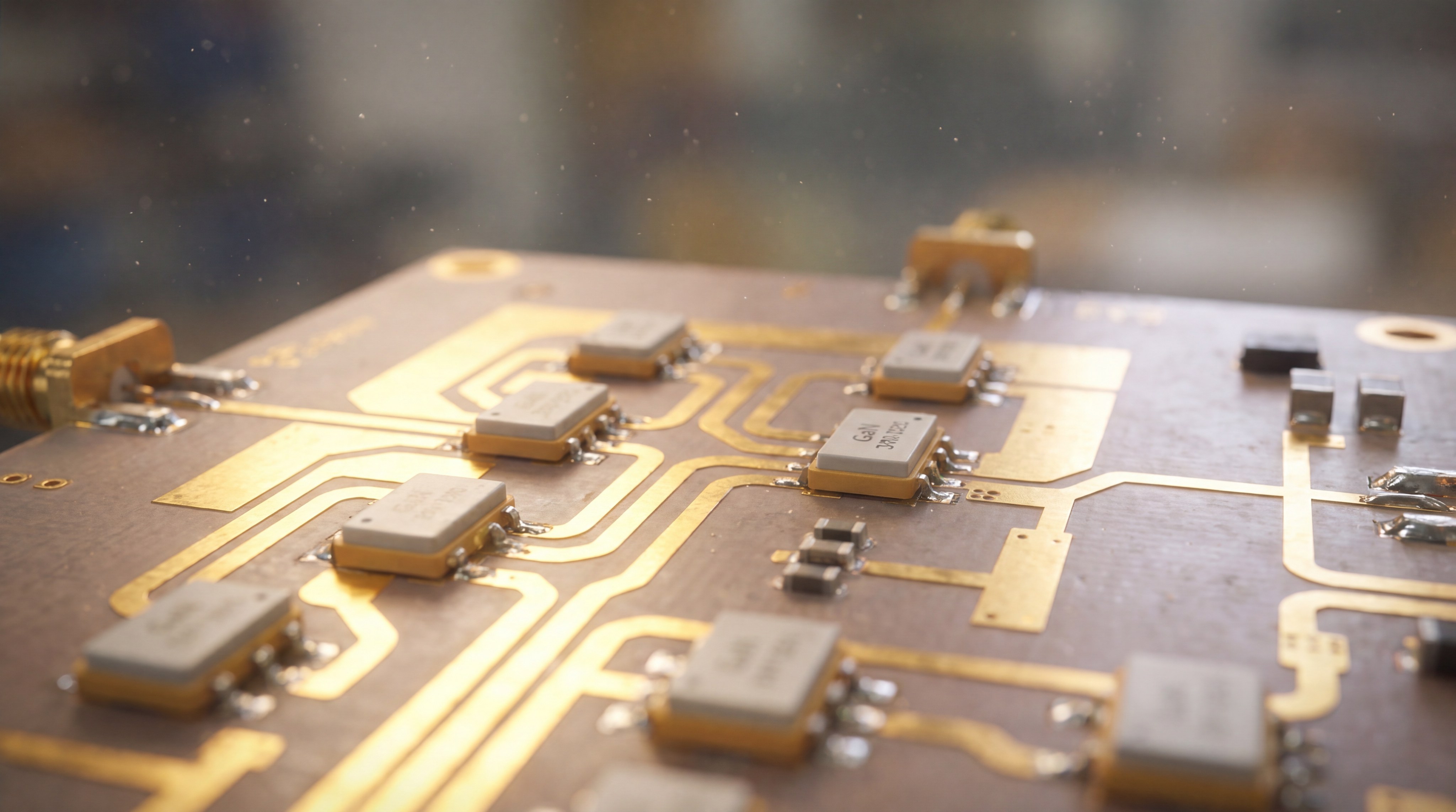
- Input Matching: The signal enters through a network that minimizes reflections.
- Active Modulation: The transistor (GaN or LDMOS) switches the DC supply current.
- Harmonic Filtering: Unwanted frequencies generated during amplification are removed.
How is the output power calculated?
Look:
Engineers measure the success of this magnification using gain, which is the ratio of output power to input power expressed in decibels (dB). For example, a 20 dB gain means your RF Amplifier has increased the signal power by a factor of 100.
Key Takeaway: Successful signal magnification depends on the efficient conversion of DC energy into RF power through high-precision semiconductor modulation.
| Process Step | Hardware Used | Objective |
|---|---|---|
| Transformation | LC Matching Networks | Impedance matching |
| Switching | Transistor Die | Power conversion |
| Conditioning | Output Filters | Signal purity |
Understanding the internal mechanics of magnification helps you troubleshoot issues like gain flatness and spectral regrowth.
Which semiconductor material is best for your project?
The best semiconductor for your RF Amplifier project depends on whether you prioritize high-frequency bandwidth, total output power, or manufacturing cost. Currently, the market is divided between legacy silicon-based solutions and advanced wide-bandgap materials like Gallium Nitride (GaN).
The truth is:
While older technologies are still viable for low-frequency applications, modern high-data-rate systems almost exclusively require advanced materials. You need to assess your frequency requirements before committing to a specific hardware architecture.
Why is LDMOS still relevant?
Laterally Diffused Metal Oxide Semiconductor (LDMOS) is the workhorse for high-power applications below 3.5 GHz.
- Ruggedness: It handles high Voltage Standing Wave Ratio (VSWR) mismatches without failing.
- Cost: It is significantly more affordable for high-volume broadcast and radio projects.
- Maturity: The design tools and manufacturing processes are highly refined and reliable.
What makes GaN the superior choice for mmWave?
Best of all:
GaN provides significantly higher power density, allowing for smaller form factors and higher efficiency at millimeter-wave frequencies. It supports the wide bandwidths required for 5G and satellite communications that other materials simply cannot reach.
Key Takeaway: Selecting the right semiconductor material ensures your RF Amplifier can handle the specific thermal and frequency demands of your application.
| Technology | Max Frequency | Power Density | Cost Profile |
|---|---|---|---|
| LDMOS | < 4 GHz | Moderate | Low |
| GaN | > 100 GHz | Very High | High |
| GaAs | > 40 GHz | Low | Moderate |
Evaluating these material trade-offs is essential for balancing project budgets against the necessary performance specifications.
How are conduction angles used to categorize devices?
Conduction angles categorize an RF Amplifier into different “classes” based on how much of the signal cycle the active transistor is conducting current. This classification is vital because it determines the fundamental trade-off between the linearity of the output and the efficiency of the power usage.
You see:
In a high-linearity class, the transistor is always on, which results in a perfect signal but wastes a lot of energy as heat. In high-efficiency classes, the transistor switches on and off, saving power but potentially distorting the signal waveform.
What are the characteristics of Class A and AB?
Most communication systems rely on these two classes to ensure data integrity remains high:
- Class A: Conducts for the full 360 degrees; provides the highest linearity but very low efficiency.
- Class AB: The industry standard; conducts between 180 and 360 degrees to balance signal quality with power savings.
How do switching classes like Class E work?
Consider this:
Class E and F amplifiers are designed as “switching” modes where the transistor acts like a high-speed toggle. This maximizes efficiency by ensuring the transistor is never in a state where it is dissipating high voltage and high current simultaneously.
Key Takeaway: The class of operation dictates whether your RF Amplifier will be a power-hungry linear device or an efficient switching booster.
| Class | Conduction Angle | Linearity | Typical Efficiency |
|---|---|---|---|
| A | 360° | Excellent | 25% |
| AB | 180° – 360° | Good | 50% |
| C | < 180° | Poor | 75% |
Selecting the appropriate class is the most effective way to manage the battery life and thermal output of your wireless hardware.
Why is impedance matching critical for signal integrity?
Impedance matching is critical for an RF Amplifier because it ensures that the maximum amount of signal energy is transferred from the source to the load without being reflected back. In high-frequency circuits, any mismatch in impedance acts like a wall, causing the signal to bounce back toward the amplifier and potentially causing catastrophic hardware failure.
In fact:
Reflected power doesn’t just reduce your signal range; it creates standing waves that generate intense heat at the output stage. You must use matching networks to transform the standard 50-ohm system impedance to the specific complex impedance of the transistor.
How do engineers achieve a perfect match?
Matching is an iterative process that involves both software simulation and physical hardware tuning:
- Smith Charts: Used to calculate the necessary values for inductors and capacitors.
- Microstrip Lines: Printed on the PCB to act as impedance transformers at high frequencies.
- Directional Couplers: Used to monitor reflected power in real-time during operation.
What happens if the match is poor?
Look:
A high VSWR (Voltage Standing Wave Ratio) indicates a poor match, which leads to gain ripples and increased distortion. If the VSWR exceeds a certain threshold, the RF Amplifier may trigger a protection circuit and shut down entirely.
Key Takeaway: Precise impedance matching is the only way to protect your RF Amplifier from reflected power while maximizing transmission range.
| Metric | Optimal Range | Impact of Failure |
|---|---|---|
| VSWR | 1.1:1 to 1.5:1 | Overheating / Damage |
| Return Loss | < -20 dB | Reduced Gain |
| S11 Parameter | Low Magnitude | Signal Reflection |
Investing time in proper impedance matching during the design phase saves significant costs in hardware replacements and field repairs.
What are the primary metrics for evaluating hardware?
Evaluating the performance of an RF Amplifier requires an analysis of gain, noise figure, and linearity metrics to determine if the device meets system requirements. These numbers tell you how much the signal is boosted, how much “hiss” is added to the background, and how much the signal is squashed at high power levels.
By the way:
A common mistake is looking only at the peak power without considering the 1dB compression point (P1dB). This metric tells you exactly where the amplifier begins to lose its linear behavior, which is critical for digital modulation schemes.
What are the most important linearity metrics?
You need to look at how the device handles signals as they approach the saturation limit:
- P1dB: The point where the output power is 1 dB lower than the ideal linear gain.
- IP3: The third-order intercept point used to predict intermodulation distortion.
- ACLR: Adjacent Channel Leakage Ratio, which measures how much signal “bleeds” into neighboring channels.
Why does Noise Figure matter for receivers?
Look:
For a receiver-side RF Amplifier, the Noise Figure (NF) is the most vital metric because it defines the sensitivity of the entire system. A low NF ensures that the amplifier doesn’t mask weak incoming signals with its own internal electronic noise.
Key Takeaway: Primary performance metrics allow you to benchmark an RF Amplifier against the specific link budget and sensitivity needs of your project.
| Metric | Unit | Higher or Lower Better? |
|---|---|---|
| Gain | dB | Higher (depending on need) |
| Noise Figure | dB | Lower |
| P1dB | dBm | Higher |
Analytical Review: These metrics provide a standardized way to compare hardware from different manufacturers to ensure consistent system performance.

How does thermal management impact long-term reliability?
Thermal management directly impacts the reliability of an RF Amplifier by preventing the internal transistor junctions from exceeding their rated temperature limits. Because these devices convert a significant portion of DC energy into waste heat, they require robust cooling solutions to maintain a stable Mean Time Between Failures (MTBF).
Consider this:
For every 10-degree Celsius increase in operating temperature, the lifespan of a semiconductor device is typically cut in half. You must integrate effective heat dissipation strategies into your mechanical design from day one.
What are the common cooling techniques?
Modern systems use a variety of active and passive methods to move heat away from the sensitive RF die:
- Conduction Cooling: Using copper baseplates to pull heat into a larger chassis.
- Forced Air: Utilizing high-speed fans and aluminum fins to increase convection.
- Liquid Cooling: Employing coolant loops for multi-kilowatt high-power systems.
How do thermal vias assist in heat transfer?
Look:
In small-form-factor designs, thermal vias are drilled into the PCB directly under the RF Amplifier pad. These copper-filled holes act as thermal “pipes,” allowing heat to escape from the top layer of the board to the bottom ground plane or heat sink.
Key Takeaway: Effective thermal management is the primary factor in ensuring your RF Amplifier operates for its intended service life without degradation.
| Cooling Level | Power Range | Complexity |
|---|---|---|
| Passive Sink | < 10 Watts | Very Low |
| Forced Air | 10 – 500 Watts | Moderate |
| Liquid Cooled | > 1 kW | High |
This breakdown illustrates that as your power requirements increase, your investment in thermal engineering must grow proportionally to ensure hardware safety.
Which linearization techniques improve output quality?
Linearization techniques improve the output quality of an RF Amplifier by correcting the non-linear distortions that occur when the device is driven at high power levels. These methods are essential for modern wideband signals like 5G, where “spectral regrowth” can interfere with adjacent users and degrade the overall network capacity.
Believe it or not:
Without linearization, you would have to run your amplifier at a much lower power than it is capable of just to keep the signal clean. By using these techniques, you can push the device closer to its maximum output while maintaining a pristine waveform.
What is Digital Predistortion (DPD)?
DPD is the most common technique used in modern telecom base stations and software-defined radios:
- Signal Analysis: The output is sampled and compared to the original input.
- Inverse Correction: A digital processor applies an “inverse” of the distortion to the input signal.
- Cancellation: The amplifier’s distortion and the predistortion cancel each other out at the output.
How does the Doherty architecture help?
Look:
The Doherty amplifier is a hardware-based linearization and efficiency booster. It uses two separate paths—a carrier and a peaking stage—to ensure the RF Amplifier remains efficient even when the signal power is fluctuating rapidly.
Key Takeaway: Linearization allows you to maximize the efficiency of your RF Amplifier without violating strict spectral emission masks.
| Technique | Implementation | Primary Benefit |
|---|---|---|
| DPD | Software/DSP | Wideband Linearization |
| Feedforward | Analog Hardware | Extreme Purity |
| Doherty | Circuit Layout | Efficiency at Back-off |
Choosing the right linearization strategy is the key to achieving high data rates and regulatory compliance in modern wireless infrastructure.
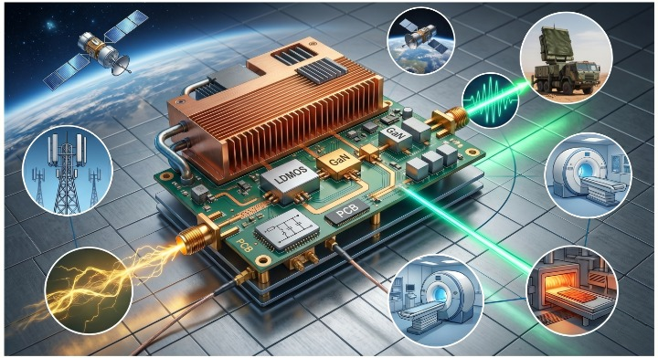
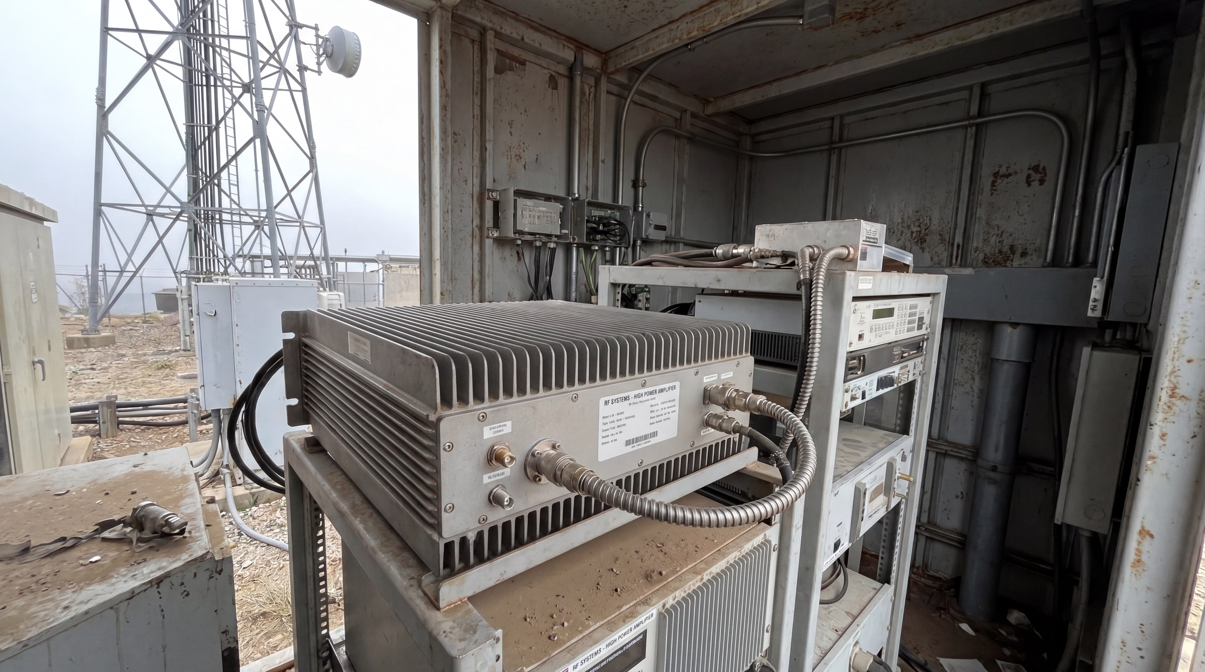
Where are these power systems deployed in the real world?
Power systems featuring an RF Amplifier are deployed in nearly every sector that requires wireless data transfer, from consumer smartphones to deep-space satellite ground stations. These components provide the muscle behind the world’s most critical communication and sensing infrastructures, operating silently in the background of our digital lives.
Think about it:
Every time you use your phone, a small amplifier in the handset boosts your signal to reach the tower, while a much larger amplifier in the base station boosts the signal to reach you. The scale of deployment ranges from milliwatt-level chips to multi-kilowatt transmitter racks.
Are they used in defense and aerospace?
In the defense sector, high-power amplification is a matter of national security and tactical advantage:
- Radar Systems: Pulsed amplifiers detect objects hundreds of miles away.
- Electronic Warfare: Wideband jammers use high-power output to disrupt enemy links.
- Satellite Uplinks: High-frequency boosters transmit data to orbiting constellations.
What about medical and industrial uses?
Look:
Beyond communication, an RF Amplifier is a core component in specialized industrial equipment. For example, MRI machines use powerful RF pulses to align atomic nuclei for medical imaging, while industrial heating systems use RF energy to cure materials in manufacturing.
Key Takeaway: Real-world applications of the RF Amplifier are diverse, spanning telecommunications, national defense, healthcare, and industrial processing.
| Industry | Typical Power | Frequency Band |
|---|---|---|
| Mobile Telecom | 20W – 80W | 600 MHz – 6 GHz |
| Satellite (Ka) | 100W – 500W | 26 GHz – 40 GHz |
| Radar Defense | 1kW – 20kW+ | 1 GHz – 18 GHz |
This diversity of use cases underscores why specialized amplifier engineering is a strategic requirement for global technological growth.
How do you choose the right power combining method?
Choosing the right power combining method for an RF Amplifier depends on your target output power, frequency range, and the allowable physical size of the system. Power combining allows you to overcome the power limits of a single transistor by summing the outputs of multiple modules into a single high-power stream.
Look:
If one module in a combined system fails, a well-designed combiner will allow the rest of the system to continue operating at reduced power. This “graceful degradation” is essential for broadcast and radar systems where downtime is not an option.
What is the corporate combining structure?
Corporate combiners are the most common architecture for merging two, four, or eight individual modules:
- Wilkinson Combiners: Provide excellent isolation between ports using resistors.
- Low Loss: Designed to ensure minimal power is lost as heat during the summation.
- Symmetry: Requires identical phase and amplitude across all paths to work effectively.
When are waveguide combiners necessary?
In fact:
For extremely high-power applications—such as those exceeding one kilowatt—standard PCB-based combiners will melt. In these cases, you must use waveguide combiners, which use hollow metal tubes to guide and sum the high-energy RF waves with very low insertion loss.
Key Takeaway: Power combining is the primary strategy for building high-wattage systems that exceed the thermal and electrical limits of a single RF Amplifier device.
| Method | Best For | Typical Power Limit |
|---|---|---|
| Wilkinson | PCB Modules | ~500 Watts |
| Hybrid Coupler | Phase Control | ~1 kW |
| Waveguide | Extreme Power | > 10 kW |
By mastering combining techniques, you can scale your RF output to meet the most demanding long-range transmission requirements.
*
Conclusion
Building a high-performance wireless system requires a deep understanding of the RF Amplifier and its complex interplay between gain, efficiency, and signal purity. We have explored the fundamental role these devices play in magnifying signals, the critical nature of impedance matching, and the advanced linearization techniques that make modern high-speed data possible. As communication demands continue to shift toward higher frequencies and wider bandwidths, the engineering behind these power systems will remain the cornerstone of global connectivity.
Whether you are designing a low-power UAV link or a multi-kilowatt radar array, the principles of semiconductor selection and thermal management are universal. We invite you to leverage our 30+ years of engineering experience to solve your most challenging signal transmission problems. Please contact us today to discuss your specific RF project requirements and discover how our factory-direct manufacturing can accelerate your path to market.
FAQ
- Can I use any amplifier for my 5G project?
No, you must choose a device designed for specific 5G frequency bands and with enough linearity to support high-order modulation. An RF Amplifier without proper DPD support or GaN technology will likely fail to meet 5G spectral mask requirements. - What is the difference between gain and power?
Gain is a ratio of how much the signal is increased, while power is the absolute measure of the energy at the output. A high-gain RF Amplifier can still have a low total power output if the input signal is very weak. - Why do amplifiers get so hot during operation?
Heat is the result of inefficiency in the DC-to-RF conversion process. For example, a Class A RF Amplifier converts about 75% of its consumed DC energy into heat, requiring significant thermal management. - How do I know if my amplifier is oscillating?
Unstable operation often appears as unexpected “spikes” on a spectrum analyzer or a sudden jump in current draw. You can mitigate this by improving the input/output matching and ensuring solid RF grounding. - Is GaN always better than LDMOS?
Not necessarily. For high-power applications at low frequencies (below 2 GHz), LDMOS is often more cost-effective and rugged than GaN for a standard RF Amplifier design.