
The wide and diverse world of RF antennas encompasses the critical hardware used to bridge the gap between electrical signals and wireless electromagnetic waves. Imagine you are managing a high-stakes industrial deployment where a single signal dropout could halt production or compromise vital data integrity. This common frustration often stems from selecting a generic component that cannot handle the specific interference or environmental stressors of your facility. By integrating precision-engineered RF Antennas from https://corelixrf.com/, you transform vulnerable wireless links into robust, high-performance communication channels that secure your operational continuity.
What Are the Fundamental Functions of Electromagnetic Antennas?
Electromagnetic antennas serve as the critical interface that converts guided electrical signals into radiating energy, which is the primary role of all RF Antennas. These components act as transducers, ensuring that high-frequency alternating currents are transformed into waves that can travel through space.

How Do Antennas Convert Conducted Signals to Radiated Energy?
When high-frequency currents flow through a conductor, they create time-varying electric and magnetic fields that detach from the structure as waves. You must ensure the physical dimensions of the conductor are precisely matched to the target wavelength to achieve resonance.
Here is the deal:
- Conductor materials provide the primary path for current flow.
- Dielectric substrates influence the velocity of wave propagation.
- Resonance ensures maximum power transfer to the atmosphere.
Why Are Conductor and Dielectric Materials Essential?
The selection of materials directly impacts the loss tangent and overall efficiency of the radiating element within the system. If you choose low-quality dielectrics, you risk signal dissipation as heat rather than radiated power.
Think about it:
- High-conductivity metals like copper reduce ohmic losses.
- Stable dielectrics prevent frequency drifting during temperature shifts.
- Material durability determines the lifespan in outdoor settings.
What Role Do Antennas Play in Distant Communication?
Antennas eliminate the need for physical cabling by enabling signals to propagate through the atmosphere over vast distances. They act as the “ears” and “mouth” of your system, defining the spatial reach and clarity of your network.
The bottom line:
- Antennas bridge the gap between isolated devices.
- They allow for mobile connectivity without tethered constraints.
- Optimized designs maximize the signal-to-noise ratio at the receiver.
Key Takeaway: Understanding the transducer nature of antennas allows you to optimize the physical layer of your wireless infrastructure for maximum efficiency.
| Component | Function | Primary Benefit |
|---|---|---|
| Conductor | Current Path | Reduces Power Loss |
| Dielectric | Field Support | Controls Impedance |
| Geometry | Wave Shaping | Determines Range |
The interaction between material properties and physical geometry remains the cornerstone of predictable signal radiation in any industrial environment.
How Do Omnidirectional and Directional Antenna Patterns Differ?
The distinction between omnidirectional and directional patterns refers to how RF Antennas distribute energy spatially, either 360 degrees horizontally or in a targeted direction. Choosing the right RF Antennas from https://corelixrf.com/omnidirectional-wideband-antennas/ depends entirely on whether you need a broad coverage “donut” or a targeted point-to-point link.
What Determines a 360-Degree Horizontal Radiation Pattern?
An omnidirectional pattern is typically produced by a vertical dipole or monopole, spreading energy equally across the horizontal plane. You should deploy these when the relative position of the receiving units is unknown or constantly changing.
Look at it this way:
- 360-degree coverage is ideal for central base stations.
- Uniform signal distribution prevents “dead zones” in mobile environments.
- Simple mounting requirements reduce installation complexity.
In Which Scenarios Is a Limited Horizontal Pattern More Efficient?
Directional patterns focus energy in a single direction, which significantly increases the effective range and reduces interference from other sources. You would utilize this when you need to connect two fixed locations or penetrate heavy obstacles.
It gets better:
- Higher gain is achieved by narrowing the beamwidth.
- Interference rejection is improved by ignoring off-axis signals.
- Reduced power waste ensures more efficient battery usage in remote sensors.
Key Takeaway: Pattern selection is a critical trade-off between the desired coverage area and the required signal reach.
| Pattern Type | Coverage Angle | Best Use Case |
|---|---|---|
| Omnidirectional | 360 Degrees | Mobile/Broadcast |
| Directional | 10 – 90 Degrees | Point-to-Point |
| Sector | 60 – 120 Degrees | Cellular/WISP |
Strategic pattern selection ensures that power is not wasted in directions where there are no intended receivers or active devices.
When Should You Use Highly Directional Yagi Antennas?
You should use highly directional Yagi antennas when your application requires long-range, point-to-point communication through high-performance RF Antennas. These designs utilize a series of parasitic elements to focus the signal into a narrow, powerful beam that cuts through noise.

How Do Yagi Antennas Support Long-Distance Transmission?
By adding directors and reflectors to a driven element, Yagi designs progressively narrow the radiation pattern to increase forward gain. This allows you to maintain a clear link even when the transmitter is miles away.
The best part?
- High front-to-back ratios prevent noise from behind the antenna.
- Lightweight boom designs allow for easy rooftop mounting.
- Frequency-specific tuning maximizes efficiency for narrow bands.
What Are the Primary Applications for Gain Horn Antennas?
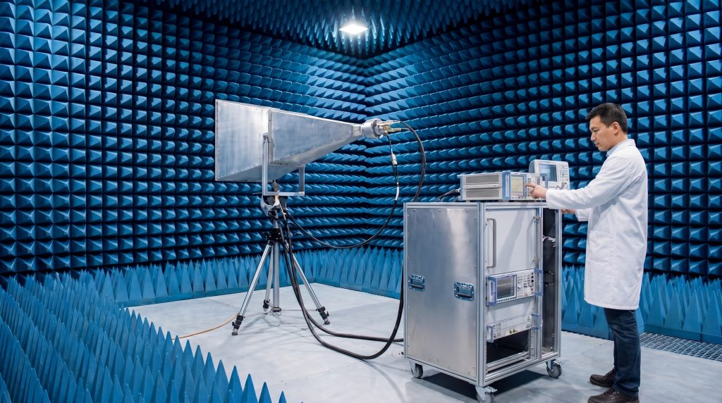
Waveguide gain horn antennas are the gold standard for microwave testing and satellite communication due to their high power handling. You will find them essential in laboratory environments where precision and wide bandwidth are non-negotiable.
Consider this:
- Horns offer excellent impedance matching over a wide range.
- Their flared structure reduces diffraction at the aperture edges.
- They provide highly predictable and stable radiation patterns.
Key Takeaway: High directivity is the most effective way to overcome significant path loss in long-range or high-frequency wireless systems.
| Antenna Type | Directivity | Common Application |
|---|---|---|
| Yagi-Uda | High | Long-range Telemetry |
| Gain Horn | Very High | RF Lab Testing |
| Parabolic | Extreme | Satellite Downlinks |
The physical length and element count of a Yagi directly correlate to the precision and intensity of its directional focus.
Why Are Panel and Patch Antennas Popular in Industrial Telecommunications?
Panel and patch antennas are favored because they offer a low-profile, aesthetic design that is easily integrated into infrastructure using modern RF Antennas. Utilizing these RF Antennas from https://corelixrf.com/antenna/ allows you to deploy high-gain solutions without the bulk of traditional structures.
How Do Low-Weight Flat Panel Designs Reduce Costs?
Flat panel antennas use printed circuit board technology, which allows for mass production at a significantly lower price point. You benefit from reduced shipping costs and simplified mounting hardware due to their aerodynamic, lightweight nature.
Think about it:
- Integrated mounting brackets speed up field deployments.
- Weatherproof housings eliminate the need for secondary enclosures.
- Low visual impact reduces zoning hurdles in urban areas.
Why Are These Form Factors Preferred for Consumer RF?
Patch antennas are small enough to be integrated directly onto the internal PCBs of routers and mobile devices. You get reliable performance in a package that fits inside the palm of your hand without external protrusions.
The reality is:
- Multi-patch arrays can be used for advanced beamforming.
- Substrate choice allows for ultra-thin, flexible designs.
- Surface-mount capabilities reduce assembly time in manufacturing.
Key Takeaway: Flat-form factors bridge the gap between high performance and practical, unobtrusive deployment in industrial and consumer settings.
| Feature | Patch Antenna | Traditional Dipole |
|---|---|---|
| Profile | Low/Flat | Protruding/Rod |
| Integration | PCB Surface | External Port |
| Durability | High (Enclosed) | Moderate (Exposed) |
This comparison highlights why modern industrial design favors integrated patch solutions over traditional external whip antennas for sleek installations.
How Do Dome Antennas Optimize Performance on Mobile Platforms?
Dome antennas optimize mobile performance by providing a rugged, low-profile housing that protects the sensitive radiating elements of RF Antennas. These designs are the standard for vehicles and aircraft where environmental exposure and aerodynamics are constant factors.
Why Are Low-Profile Designs Preferred for Vehicles?
A low-profile “shark fin” or dome design prevents the antenna from being snagged by low-hanging obstacles like branches or garages. You ensure that your communication remains uninterrupted even during high-velocity transit or rough terrain.
The bottom line:
- Reduced height limits physical damage from accidental impacts.
- Aerodynamic shaping improves the fuel efficiency of the vehicle.
- Sealed bases prevent moisture ingress into the electronic cabin.
How Do Dome Structures Protect Internal Elements?
The radome material is engineered to be electromagnetically transparent while remaining physically tough against UV radiation and ice. You can trust that the internal tuning remains stable regardless of the harsh weather conditions outside.
Make no mistake:
- Impact-resistant plastics prevent physical deformation of the elements.
- UV-stabilized coatings prevent the housing from becoming brittle.
- Hermetic sealing protects against salt spray and chemicals.
Key Takeaway: Protective radomes extend the operational life of antennas in harsh mobile or outdoor environments by shielding delicate components.
| Factor | Dome Antenna | Whip Antenna |
|---|---|---|
| Vandal Resistance | High | Low |
| Weather Shielding | Excellent | Poor |
| Aesthetic Appeal | Professional | Industrial |
Choosing a dome structure is an investment in both the longevity and the aerodynamic efficiency of your mobile RF system.
What Is the Importance of Antenna Polarization in Signal Integrity?
Antenna polarization is critical because a mismatch between orientations can result in massive signal loss for RF Antennas. Properly aligning your RF Antennas using resources from https://corelixrf.com/directional-antenna/ is the fastest way to recover “missing” signal strength in your link budget.

How Does Alignment Affect the Link Budget?
If your transmitter is vertically polarized and your receiver is horizontal, the physical waves will not efficiently induce current in the receiving element. You must match the orientation to ensure the maximum electric field strength is captured by the receiver.
Think about it:
- Linear polarization is the standard for fixed point-to-point links.
- Circular polarization helps when device orientation is unpredictable.
- Polarization loss is a common cause of mysterious system failures.
Why Is Polarization Diversity Critical in Multipath?
In environments with many reflections, signals often arrive at the receiver with scrambled or rotated polarizations. You can use dual-polarized antennas to capture signals on multiple planes simultaneously, which significantly boosts data throughput.
Look at it this way:
- Diversity reduces the impact of signal fading in urban areas.
- Multiple Input Multiple Output (MIMO) systems rely on this principle.
- Cross-polarization isolation improves channel separation in dense networks.
Key Takeaway: Precise polarization management is as important as gain for maintaining a high-quality, reliable wireless connection in complex environments.
| Polarization Type | Best Environment | Key Benefit |
|---|---|---|
| Vertical | Open Terrains | Long-range stability |
| Circular | Urban/Satellite | Reduced multipath fading |
| Dual-Slope | High-Density | Increased MIMO capacity |
The alignment of the electromagnetic field is a fundamental variable that dictates the overall efficiency of every wireless link.
How Do Wideband Antennas Support Modern Multi-Frequency Systems?
Wideband antennas are designed to maintain a consistent impedance match across a very broad frequency spectrum for various RF Antennas. These components allow you to support multiple services, such as 5G and Wi-Fi, using a single physical aperture.
What Design Techniques Allow Covering Multiple Octaves?
Engineers use log-periodic or tapered slot designs to ensure that different parts of the antenna resonate at different frequencies. You avoid the need for multiple antennas on a single tower, which simplifies your system architecture significantly.
The best part?
- One antenna replaces multiple narrow-band units.
- Future-proofing is built-in as new frequency bands emerge.
- Logistic complexity is reduced with fewer units to install.
Why Is Gain Flatness a Key Performance Metric?
If gain varies wildly across the frequency range, your system will perform inconsistently depending on which channel is currently in use. You need a flat gain response to ensure that the handoff between different frequency bands is seamless for the end user.
The reality is:
- Consistent gain ensures predictable and stable coverage areas.
- It simplifies the calibration of the entire RF front-end.
- Uniform performance reduces the risk of dropped connections.
Key Takeaway: Wideband solutions offer the most efficient way to manage the complex, multi-band nature of modern industrial wireless networks.
| Specification | Wideband Antenna | Narrowband Antenna |
|---|---|---|
| Bandwidth | Very High (Octaves) | Low (<10%) |
| Design Complexity | High | Moderate |
| Versatility | Excellent | Limited |
Deploying wideband hardware is a strategic move to reduce long-term infrastructure costs and maximize spectral flexibility for future upgrades.
How Does Antenna Gain Impact Long-Range Communication?
Antenna gain measures the ability to direct energy toward a specific location, effectively extending the reach of RF Antennas. High-performance RF Antennas found at https://corelixrf.com/antenna/ allow you to reach remote sites that would otherwise be completely off-grid.
What Is the Relationship Between Beamwidth and Gain?
There is an inverse relationship where the narrower the beamwidth, the higher the concentrated gain of the antenna element. You must understand that high gain does not “create” energy; it simply focuses it more tightly, similar to a flashlight lens.
Think about it:
- Narrow beams require more precise physical alignment.
- Wider beams are more forgiving but offer much less range.
- The choice depends on the stability of your mounting platform.
Why Can Excessive Gain Complicate Alignment?
When you use ultra-high gain antennas, the “sweet spot” for signal reception may only be a few degrees wide. You might find that even slight thermal expansion or wind vibration can knock your high-gain link offline completely.
It gets better:
- High-gain links require rugged, precision mounting brackets.
- Tracking systems may be needed for moving targets like satellites.
- Specialized installation tools help ensure perfect alignment.
Key Takeaway: Gain is a powerful tool for extending range, but it demands much higher mechanical precision and mounting stability.
| Gain Level | Beamwidth | Alignment Difficulty |
|---|---|---|
| 3-6 dBi | Wide | Easy |
| 12-18 dBi | Medium | Moderate |
| 24+ dBi | Narrow | High |
This table clarifies that increasing gain always comes with the price of a more demanding and stable physical installation.
Why Is Impedance Matching Vital for Antenna System Integration?
Impedance matching ensures that the maximum amount of power is transferred from your radio to the RF Antennas without reflection. Without proper matching, your RF Antennas will underperform, and you risk damaging the sensitive electronics within your power amplifiers.
How Does VSWR Affect Power Transfer Efficiency?
The Voltage Standing Wave Ratio (VSWR) is a numerical representation of how well the antenna’s impedance matches the standard 50-ohm system. You should always aim for a VSWR of 1.5:1 or lower to ensure that over 96% of your power is radiated.
Look at it this way:
- High VSWR causes signal reflections known as return loss.
- Reflected power generates harmful heat in the transmitter.
- It can cause digital modulation errors and dropped packets.
Which Components Are Used to Achieve a 50-Ohm Match?
Engineers often use LC matching networks, baluns, or quarter-wave transformers to bridge the gap between the radiator and the cable. You can rely on these components to provide a stable electrical environment for all your high-frequency signals.
The bottom line:
- Modern antennas often have integrated matching circuits.
- Pre-tuned antennas save you hours of difficult field troubleshooting.
- Quality connectors ensure the match remains stable over time.
Key Takeaway: A well-matched impedance system is the foundation of high efficiency, signal clarity, and hardware longevity.
| VSWR Ratio | Power Reflected | Efficiency Status |
|---|---|---|
| 1.0:1 | 0% | Perfect |
| 1.5:1 | 4% | Excellent |
| 3.0:1 | 25% | Poor (Risk of damage) |
Monitoring your VSWR is the most effective way to diagnose physical layer issues before they cause a total system outage.
When Are Custom Antenna Solutions Required for Specialized Projects?
Custom antenna solutions are required when standard products cannot meet your unique mechanical or frequency constraints for RF Antennas. Bespoke RF Antennas from https://corelixrf.com/custom-antenna/ are the only way to guarantee peak performance in proprietary industrial applications.
How Do Extreme Environments Dictate Custom Form Factors?
If your project involves underwater deployment, extreme vacuum, or high-vibration aerospace environments, a standard plastic antenna will fail quickly. You need custom-engineered housings and specialized materials that can withstand the unique rigors of your specific mission profile.
Here is the deal:
- Custom mounts can be designed to fit existing airframe holes.
- Specialized coatings can resist salt-spray or corrosive chemicals.
- High-temperature materials prevent melting in industrial ovens.
How Does Custom Integration Improve System Performance?
By designing the antenna alongside the rest of your hardware, you can eliminate the losses associated with long cable runs. You achieve a more compact, efficient, and reliable final product that is optimized for its specific operating environment.
Think about it:
- Performance is optimized for your exact equipment enclosure.
- Unique frequency bands can be targeted with surgical precision.
- Integrated designs reduce the total number of failure points.
Key Takeaway: Custom engineering eliminates the compromises inherent in trying to “force” a standard antenna into a specialized industrial role.
| Project Type | Off-the-Shelf | Custom Engineered |
|---|---|---|
| Standard Wi-Fi | Ideal | Overkill |
| Aerospace Telemetry | Risky | Necessary |
| Proprietary IoT | Difficult | Optimized |
This analysis shows that as project complexity increases, the value of a custom-designed antenna solution grows exponentially.
*
In this article, we have explored the critical technical layers that define the wide and diverse world of RF antennas. From the fundamental physics of electromagnetic radiation and the strategic selection of radiation patterns to the nuances of polarization and the necessity of custom engineering, it is clear that the antenna is never “just a piece of wire.” By addressing the common problems of signal loss, interference, and environmental degradation through informed component selection, you can build wireless systems that are both resilient and high-performing.
At CorelixRF, our vision is to empower global connectivity through precision RF engineering and uncompromising quality standards. We invite you to contact us today to discuss how our expert team can optimize your next wireless project with the industry’s most reliable antenna solutions.
*
FAQ
What’s the best way to increase my wireless range?
The most effective method is increasing antenna gain. By using a directional antenna to focus energy into a narrower beam, you can significantly extend the effective distance of your link without increasing transmitter power.
Can I use an indoor antenna for an outdoor application?
Generally, no, because indoor antennas lack the UV stabilization and moisture sealing required for outdoor exposure. Using them outside will lead to rapid corrosion and physical failure of the internal elements.
How do I know if my antenna is properly matched?
You must measure the VSWR or Return Loss using a Network Analyzer or SWR meter. A reading of 1.5:1 or lower indicates that the antenna is efficiently transferring power with minimal reflections.
What’s the best antenna for a moving vehicle?
An omnidirectional dome antenna is typically the best choice. This design provides 360-degree coverage so the link remains stable regardless of the vehicle’s orientation, while the dome protects against wind and impacts.
Can I paint an antenna to match my building?
Only if you use non-conductive, RF-transparent paint. Many standard paints contain metallic particles that will detune the antenna and block the signal, potentially causing hardware damage.