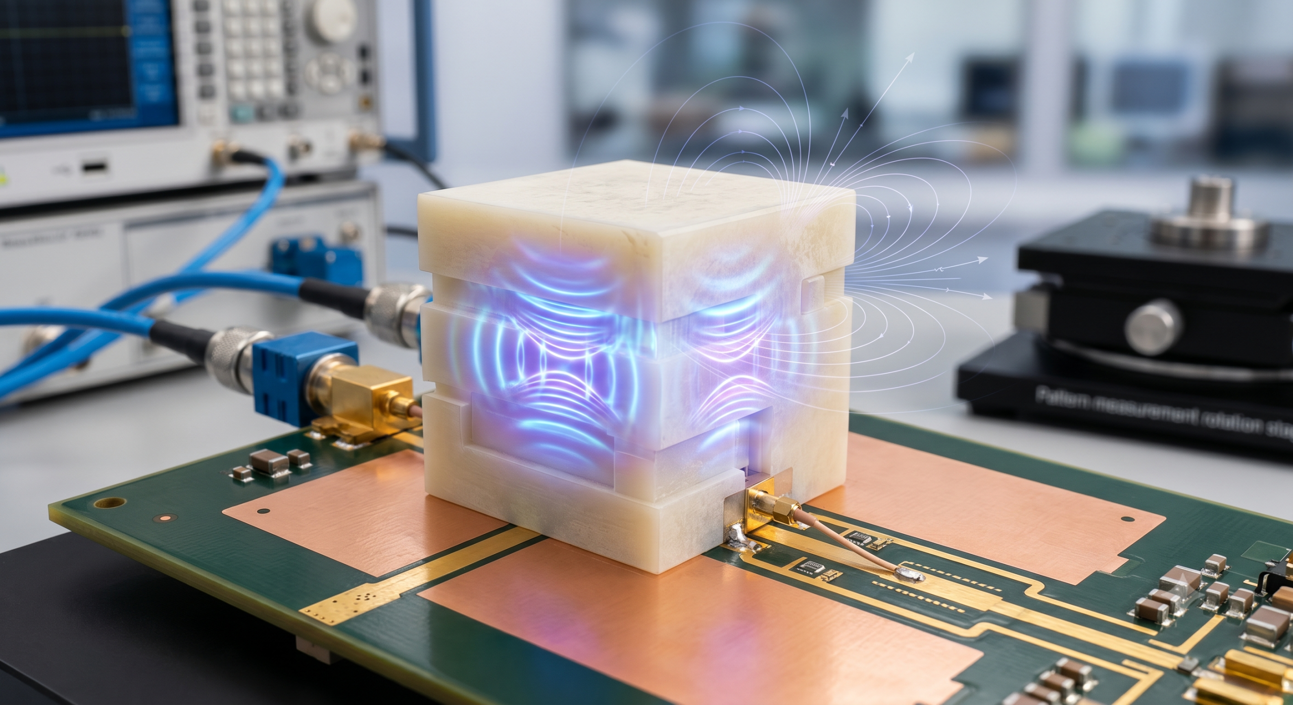
A Dielectric Resonator Antenna (DRA) is a radio frequency radiator that utilizes a block of non-conductive, high-permittivity ceramic material to transmit and receive electromagnetic signals. You often encounter significant signal degradation and thermal issues when using traditional metallic antennas in high-frequency microwave applications. These energy losses agitate your design cycle, forcing you to compensate with higher power levels that increase system complexity. By switching to a dielectric resonator, you obtain a high-efficiency solution that thrives at millimeter-wave frequencies without the conduction losses of metal.
Match the antenna design to a complete RF chain
For antenna projects that also need amplifier, signal source or front-end integration, CorelixRF can review frequency range, gain, polarization, connector, enclosure and validation requirements before quotation.
What defines a dielectric resonator antenna?
A Dielectric Resonator Antenna is defined by its use of a dielectric material as the radiating element instead of a conductive metal skin. You will find that these antennas operate by supporting standing waves within a ceramic volume, which then leaks energy into the air as radiation. This mechanism allows you to achieve resonance in a much smaller physical footprint than traditional wire or patch antennas.
What is a resonant dielectric radiator?
A resonant dielectric radiator is a piece of low-loss material that allows electromagnetic fields to oscillate within its boundaries at specific frequencies. You can tune these frequencies by adjusting the physical dimensions and the dielectric constant of the material itself.
- Ceramic resonators.
- Low-loss glass.
- Engineered composites.
Think about it:
The absence of a metallic surface means you are no longer limited by the skin effect at extremely high frequencies.
What is the basic structural composition?
The structural composition of a DRA typically includes a dielectric block, a feeding mechanism, and a ground plane to direct the signal. You will see that the feeding mechanism, such as a microstrip line or a probe, is responsible for coupling energy into the dielectric body.
- Dielectric radiating body.
- Feeding probe or slot.
- Conducting ground plane.
The best part?
You can easily integrate these simple components into standard PCB manufacturing workflows without specialized tooling.
How does it convert electromagnetic waves?
It converts electromagnetic waves by establishing displacement currents within the dielectric material that oscillate in response to an input signal. You rely on these internal field distributions to create the radiation patterns required for your wireless link.
- Displacement current excitation.
- Field mode oscillation.
- Energy leakage to free space.
Here is the deal:
Because the material is non-conductive, the energy is radiated through the surface rather than being absorbed by the resistance of a wire.
| Feature | Description |
|---|---|
| Core Material | Non-conductive High-Permittivity Ceramic |
| Radiation Method | Displacement Currents / Field Leakage |
| Footprint | Highly Compact / Frequency Dependent |
Use this guide to determine if your frequency requirements justify moving away from metallic radiators to ceramic-based resonant structures.
Key Takeaway
The fundamental definition of a DRA centers on using ceramic materials to support resonant electromagnetic fields. This approach allows you to bypass the physical limitations of conductive metals while maintaining a highly compact form factor.
Why are these antennas highly efficient?
The Dielectric Resonator Antenna is highly efficient because it virtually eliminates the ohmic losses found in traditional metallic antennas. You will notice that as frequencies increase into the GHz range, the resistance of metal rises, but the dielectric material remains consistently low-loss. This ensures that a greater percentage of your power is actually radiated rather than wasted as heat.
How are conduction losses eliminated?
Conduction losses are eliminated because the primary radiating element is a dielectric material that does not support the flow of electrons through a resistive path. You are essentially replacing the “skin” of a metal antenna with a volume of ceramic that possesses no DC conductivity.
- Zero metallic skin effect.
- No resistive heating.
- Minimal dielectric dissipation.
The best part?
You save on thermal management costs because your antenna stays cool even during high-power transmissions.
What ensures high radiation performance?
High radiation performance is ensured by the high radiation resistance that these antennas naturally possess compared to their loss resistance. You benefit from a high radiation efficiency, often exceeding 95% even at millimeter-wave frequencies.
- High radiation resistance.
- Low internal loss.
- Optimized coupling efficiency.
Think about it:
Higher efficiency means you can achieve the same range with less battery power or smaller amplifiers in your RF chain.
What are the advantages at high frequencies?
At high frequencies, the dielectric resonator becomes the superior choice because it maintains its performance while metal antennas become increasingly difficult to manufacture and tune. You will find that the physical size of the DRA remains manageable even as wavelengths shrink into the millimeter range.
- Frequency stability.
- Scalable dimensions.
- Low-loss material properties.
Here is the deal:
When your project moves into the 24GHz or 60GHz bands, the efficiency gains of a DRA become too significant to ignore.
| Metric | Metallic Antenna | Dielectric Resonator Antenna |
|---|---|---|
| Conduction Loss | High (at mmWave) | Negligible |
| Radiation Efficiency | 50% – 80% | 90% – 99% |
| Thermal Stability | Low | High |
Analyze these efficiency metrics to see how much power your current system is wasting through conduction losses in traditional patch or wire designs.
Key Takeaway
High efficiency is the hallmark of the DRA, achieved through the total removal of metallic conduction losses. This makes it the ideal choice for high-frequency systems where every milliwatt of radiated power is critical for link budget success.
How does material choice affect antenna size?
A Dielectric Resonator Antenna scales its size based on the dielectric constant of the material you choose for the design. You can significantly reduce the physical volume of the radiator by selecting materials with higher permittivity, which slows down the electromagnetic wave. This allows you to fit high-performance antennas into extremely tight enclosures that cannot accommodate metallic counterparts.
What is the role of relative permittivity?
Relative permittivity, or the dielectric constant, determines how much the wavelength of the signal is compressed inside the material. You will find that as the permittivity increases, the required resonant size of the antenna decreases proportionally.
- Wavelength compression.
- Energy confinement.
- Resonant frequency tuning.
Think about it:
Choosing a material with a permittivity of 10 instead of 2 can shrink your antenna’s volume by a factor of nearly five.
How does scaling enable compact dimensions?
Scaling enables compact dimensions by allowing the antenna to be much smaller than the wavelength in free space. You can design antennas that are only a fraction of a centimeter wide even for lower-frequency applications where traditional antennas are bulky.
- Sub-wavelength design.
- Volumetric efficiency.
- Reduced component footprint.
The best part?
Small antennas are easier to integrate into portable devices and wearables where internal space is at a premium.
How do they compare to metallic antennas?
Compared to metallic antennas, DRAs offer a much better size-to-bandwidth ratio because they utilize their entire volume for radiation. You will avoid the narrow-band limitations often found in small microstrip patch antennas while maintaining a similar or smaller footprint.
- Volume vs. surface area.
- Wider impedance bandwidth.
- Flexible geometric shapes.
Here is the deal:
You no longer have to choose between a tiny antenna and a high-performance one; the DRA provides both through material engineering.
| Permittivity ($\epsilon_r$) | Size Reduction Factor | Typical Material |
|---|---|---|
| 4 | 2x | Low-loss Polymer |
| 10 | 3.1x | Alumina Ceramic |
| 40 | 6.3x | High-K Ceramic |
Use this sizing table to estimate how much space you can reclaim in your system by upgrading to a high-permittivity resonator material.
Key Takeaway
Material choice is the primary lever for controlling antenna size in DRA designs. By selecting high-permittivity ceramics, you can achieve massive size reductions without sacrificing the radiation efficiency needed for reliable communication.
What design variables can engineers control?
The Dielectric Resonator Antenna offers you a wide range of tunable parameters, from its physical shape to its feed location. You can precisely control the impedance bandwidth and polarization characteristics by varying the height-to-width ratio of the ceramic block. This level of design flexibility is far superior to that of traditional antennas, where geometry is often fixed by the radiator’s length.
How is impedance bandwidth managed?
Impedance bandwidth is managed by adjusting the aspect ratio of the resonator and selecting the appropriate material permittivity. You can widen the operating range by lowering the permittivity or by choosing specific shapes like cylinders or hemispheres that naturally support broader modes.
- Aspect ratio tuning.
- Multi-mode excitation.
- Material selection.
The best part?
You can stack different dielectric layers to create ultra-wideband responses that cover multiple communication standards at once.
How are polarization and gain controlled?
Polarization and gain are controlled by the orientation of the excitation feed and the symmetry of the resonator itself. You can achieve circular polarization by using two feeds or by introducing slight asymmetries into the shape of the ceramic block.
- Feed position offset.
- Shape perturbation.
- Cross-polarization suppression.
Think about it:
Gaining control over these variables allows you to optimize the link for satellite communications or indoor multipath environments.
What is the best way to select excitor types?
The best way to select excitor types is to match the feeding mechanism to your specific PCB integration requirements and desired frequency. You might choose a probe feed for maximum power handling or a slot feed to keep the antenna profile as low as possible.
- Coaxial probe feeds.
- Aperture-coupled slots.
- Microstrip line coupling.
Here is the deal:
Selecting the right feed is the key to ensuring that maximum energy is transferred from your amplifier into the dielectric radiator.
| Variable | Impact on Performance | Tuning Method |
|---|---|---|
| Aspect Ratio | Bandwidth and Modes | Physical dimensioning |
| Feed Position | Impedance Matching | Offset from center |
| Shape Symmetry | Polarization Type | Geometric modification |
Evaluate these design variables during your simulation phase to ensure your custom antenna meets the specific gain and bandwidth needs of your RF platform.
Key Takeaway
Engineers have unprecedented control over DRA performance through geometry and feed placement. This flexibility allows for the creation of highly customized antennas that are perfectly matched to specific B2B RF requirements.
Why is the resonator shape important?
The shape of the Dielectric Resonator Antenna is important because it determines the specific electromagnetic modes that can exist within the material. You can choose different geometries—such as rectangular, cylindrical, or hemispherical—to optimize the radiation pattern for your application. Each shape offers a unique set of boundary conditions that influence how the energy is distributed and radiated into the environment.
What are the performance and complexity tradeoffs?
Performance and complexity tradeoffs involve balancing the high gain of complex shapes with the ease of manufacturing simple ones. You might find that a rectangular block is the easiest to machine and mount, while a hemispherical shape provides better stability and radiation characteristics.
- Manufacturing cost vs. gain.
- Ease of integration.
- Modal purity.
The best part?
Rectangular shapes allow you to tune three different dimensions independently, giving you the most control over the frequency response.
What are advanced supershaped geometries?
Advanced supershaped geometries involve using non-standard curves and irregular volumes to suppress unwanted side lobes and enhance directivity. You can use these complex designs in specialized satellite or radar equipment where beam precision is more important than low-cost production.
- Optimized curvature.
- Asymmetric volumes.
- Sidelobe suppression.
Think about it:
Computer-aided optimization can now design shapes that no human would ever conceive, maximizing performance in ways standard blocks cannot.
What are the advantages of fractal designs?
Fractal designs offer the advantage of multi-band operation and significant size reduction through self-similar patterns. You can integrate fractal boundaries into the dielectric material to create an antenna that responds to several different frequencies simultaneously.
- Multi-resonant behavior.
- Compact surface area.
- Broadband capability.
Here is the deal:
Fractal shapes are perfect for modern systems that must handle 4G, 5G, and Wi-Fi signals through a single radiating aperture.
| Shape | Complexity | Primary Benefit |
|---|---|---|
| Rectangular | Low | Ease of mounting and tuning |
| Cylindrical | Medium | Better modal separation |
| Hemispherical | High | Zero surface wave losses |
Consider the manufacturing capabilities of your production line when choosing between these shapes to ensure a balance between RF performance and yield.
Key Takeaway
Geometry is the engine of performance for a DRA. By choosing the right shape, you can manipulate the electromagnetic fields to achieve specific radiation goals, from simple wide-area coverage to complex multi-band responses.
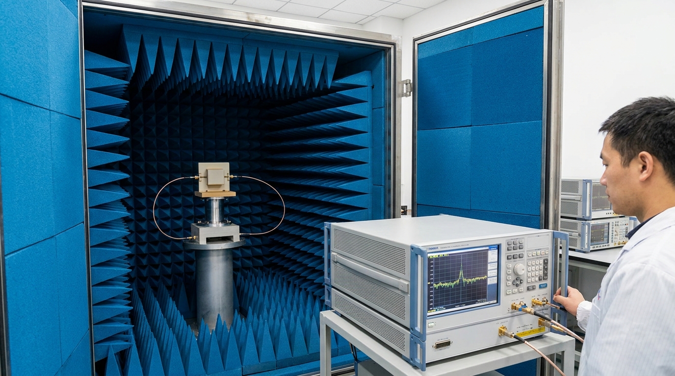
How can radiation patterns be improved?
Radiation patterns in a Dielectric Resonator Antenna can be improved by integrating external structures like lenses or by optimizing the ground plane size. You can shape the beam to be more directional or more omnidirectional depending on your system’s spatial requirements. These enhancements allow you to focus energy precisely where it is needed, increasing the effective range and reliability of your wireless link.
How are dielectric lenses used?
Dielectric lenses are used to focus the wide-angle radiation from a DRA into a narrow, high-gain beam. You can place a secondary dielectric structure in front of the primary resonator to act as a collimator for the electromagnetic waves.
- Beam collimation.
- Gain enhancement.
- Long-range focus.
The best part?
Lenses are passive components that can significantly boost your signal strength without adding any electronic complexity or power consumption.
What is the best way to optimize directivity?
The best way to optimize directivity is to adjust the placement of the DRA on the ground plane or to use a parabolic reflector. You will find that the size and shape of the metal surface beneath the antenna act as a secondary radiator that can push the beam in a specific direction.
- Ground plane sizing.
- Reflector integration.
- Phase center alignment.
Think about it:
A well-placed reflector can turn a standard 5 dBi antenna into a 15 dBi powerhouse for point-to-point links.
How do you enhance antenna patterns?
You enhance antenna patterns by using parasitic elements or by arrays that work together to shape the final beam. You can place non-fed dielectric blocks near the primary radiator to pull the electromagnetic field and flatten the radiation pattern.
- Parasitic resonator coupling.
- Pattern flattening.
- Beamwidth control.
Here is the deal:
Adding a few extra grams of ceramic can solve complex interference problems by “cleaning up” the radiation pattern in crowded RF environments.
| Pattern Enhancement | Method | Resulting Benefit |
|---|---|---|
| Lensing | External Dielectric Disk | Increased Peak Gain |
| Ground Control | Specific GP Geometry | Reduced Back-lobe Radiation |
| Parasitics | Unfed Ceramic Elements | Widened Beamwidth |
Review these enhancement techniques to determine if a simple DRA can be upgraded to meet high-directivity requirements without moving to a more expensive phased array.
Key Takeaway
Radiation patterns are not fixed; they are highly malleable through the use of lenses and reflectors. This allows you to tailor the “vision” of your antenna to match the specific geographic and spatial needs of your B2B application.
What materials are used in fabrication?
The performance of a Dielectric Resonator Antenna depends entirely on the specialized ceramics and polymers used during its fabrication. You will typically select materials with a high dielectric constant (between 10 and 100) and a very low loss tangent to maximize efficiency. These materials must also be thermally stable to ensure that the antenna’s resonant frequency does not drift when the equipment heats up during operation.
How are machined ceramic components used?
Machined ceramic components are used for high-precision applications where the physical tolerances of the antenna must be kept within microns. You will find that alumina or zirconia-based ceramics are popular because of their extreme hardness and excellent electrical properties.
- Alumina (Al2O3).
- Zirconia (ZrO2).
- Titanate-based ceramics.
The best part?
Machined ceramics can withstand harsh environmental conditions, including high temperatures and corrosive atmospheres, better than any plastic.
What is the role of advanced polymer materials?
Advanced polymer materials play a role in low-cost, high-volume production where flexible or lightweight antennas are required. You can use specialized RF-grade plastics that have been doped with ceramic powders to achieve a balance between weight and dielectric performance.
- Ceramic-filled polymers.
- Lightweight composites.
- Flexible RF plastics.
Think about it:
If your device is mobile or airborne, the weight savings from using polymers can be just as important as the RF gain.
Why use co-fired ceramic structures?
Co-fired ceramic structures are used to integrate the antenna directly into a multi-layer substrate alongside other RF components. You can use Low Temperature Co-fired Ceramic (LTCC) technology to build the resonator and the feeding network in a single, unified package.
- LTCC technology.
- Integrated feed lines.
- Miniature 3D structures.
Here is the deal:
LTCC allows you to shrink the entire RF front-end into a single chip-like module, reducing assembly costs and improving reliability.
| Material Type | Dielectric Constant | Durability |
|---|---|---|
| Hard Ceramics | 9 – 40 | Extremely High |
| LTCC | 5 – 20 | High (Integrated) |
| RF Polymers | 2 – 10 | Medium |
Select your material based on the operating environment of your product, prioritizing hard ceramics for infrastructure and polymers for consumer-grade devices.
Key Takeaway
Modern fabrication relies on high-K ceramics and advanced polymers to deliver the electrical properties needed for high-frequency resonance. These materials provide the thermal and mechanical stability required for professional B2B telecommunications.
Can these antennas be integrated on chips?
A Dielectric Resonator Antenna is perfectly suited for on-chip integration as frequencies push into the Terahertz (THz) range. You can fabricate the resonator directly on the semiconductor die, eliminating the need for lossy bond wires or connectors. This level of integration is essential for modern high-speed data links and advanced sensing applications where every millimeter of signal path matters.
How is semiconductor die integration achieved?
Semiconductor die integration is achieved by using the top layers of the chip to form the feeding network for a dielectric block placed on top. You will find that this “antenna-on-chip” (AoC) approach allows you to place the radiator microns away from the final amplifier stage.
- Wafer-level mounting.
- Direct-on-die feeding.
- Silicon-based resonators.
The best part?
By removing the interface between the chip and the board, you eliminate the most common source of signal reflection and loss.
What are the on-chip size constraints?
On-chip size constraints are the primary challenge, as the antenna must be small enough to fit within the expensive real estate of the silicon wafer. You will typically use higher-permittivity materials for on-chip DRAs to ensure they remain compact enough for millimeter-wave circuits.
- Silicon area cost.
- Height limitations.
- Proximity to other circuits.
Think about it:
At 60GHz, a DRA is small enough to fit on a standard 5mm chip, making it a viable solution for mass-produced mobile silicon.
Can they operate at extreme frequencies?
Yes, they can operate at extreme frequencies where other antenna types fail due to excessive conductor loss or manufacturing difficulty. You can use the DRA in the sub-Terahertz and Terahertz bands for medical imaging, security scanning, and 6G research.
- 100GHz to 1THz range.
- Molecular sensing.
- High-bandwidth data.
Here is the deal:
The DRA is one of the few antenna types that remains efficient at the “Terahertz gap” where traditional electronics struggle to function.
| Integration Type | Complexity | Frequency Suitability |
|---|---|---|
| On-Chip (AoC) | Extreme | > 60 GHz |
| In-Package (AiP) | High | 24 – 60 GHz |
| Off-Chip (AoB) | Low | < 24 GHz |
Analyze your system’s frequency requirements to determine if on-chip integration is necessary to overcome the losses associated with standard PCB mounting.
Key Takeaway
Dielectric resonators are the future of on-chip wireless communication. Their ability to integrate directly with semiconductor processes at high frequencies makes them indispensable for the next generation of 6G and THz electronics.
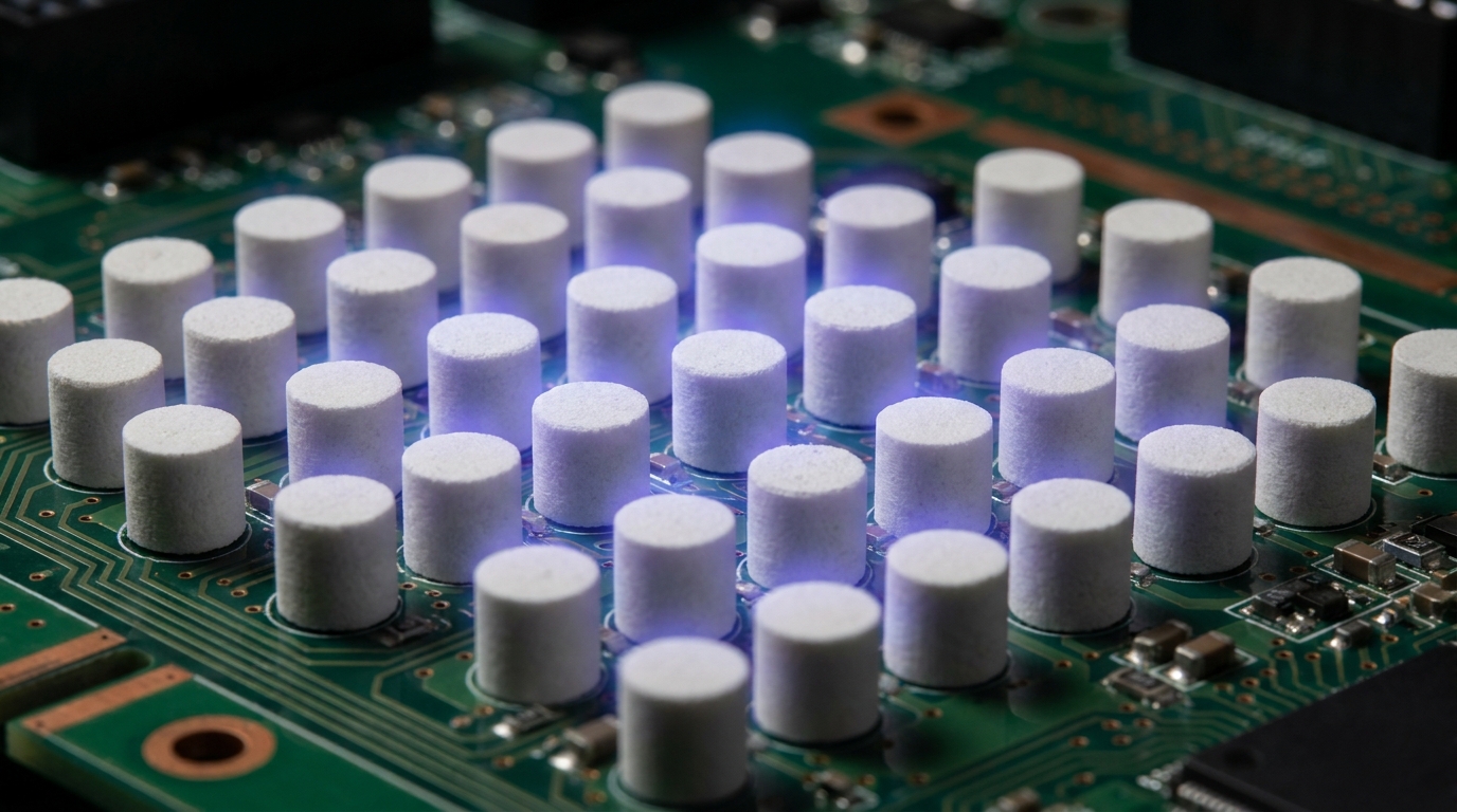
How are arrays used for beam control?
Arrays of the Dielectric Resonator Antenna are used to create highly directional beams that can be steered electronically across a wide field of view. You can combine multiple ceramic blocks into a single phased array to increase the total gain and reach of your system. This capability is vital for 5G base stations and radar systems that must track moving targets or high-speed mobile users.
What techniques are used for gain enhancement?
Techniques for gain enhancement involve feeding multiple resonators in phase so that their individual radiation patterns combine into a single, powerful beam. You will find that doubling the number of elements in your array typically increases the gain by 3 dB.
- Phased combining.
- Mutual coupling control.
- Corporate feed networks.
The best part?
A DRA array can achieve the same gain as a large satellite dish but in a flat, low-profile form factor that is easier to install.
What are the beamforming capabilities?
Beamforming capabilities allow you to shape the radiated energy into narrow beams that can be pointed in specific directions without moving the antenna physically. You achieve this by controlling the phase of the signal sent to each individual resonator in the array.
- Spatial filtering.
- Dynamic targeting.
- Multi-user MIMO.
Think about it:
You can serve multiple data streams to different locations simultaneously by splitting the array into several independent beams.
How do active elements enable beamsteering?
Active elements, such as phase shifters and variable gain amplifiers, enable real-time beamsteering by modifying the signal before it reaches the dielectric blocks. You can sweep the beam across the horizon in microseconds, allowing for rapid scanning in radar applications.
- Electronic scanning.
- Fast switching speeds.
- Software-defined coverage.
Here is the deal:
Integrating a DRA array with modern beamforming ICs gives you a smart antenna system that adapts to its environment automatically.
| Array Configuration | Number of Elements | Typical Application |
|---|---|---|
| 1×4 Linear | 4 | Automotive Radar |
| 4×4 Planar | 16 | 5G Small Cell |
| 16×16 Large | 256 | Satellite Earth Station |
Determine the required number of elements for your array by calculating the link budget and the necessary angular resolution for your project.
Key Takeaway
Phased arrays take the individual benefits of a DRA and multiply them across a system. By using beamforming, you can transform a collection of ceramic blocks into a high-gain, steerable antenna system capable of supporting advanced communication protocols.
Where is this technology primarily used?
The Dielectric Resonator Antenna is primarily used in sectors where space, efficiency, and high-frequency performance are non-negotiable. You will see these antennas in 5G infrastructure, satellite terminals, and modern automotive safety systems. As the world moves toward higher frequency bands, the DRA is quickly becoming the standard for professional-grade RF equipment.
How do modern communication systems benefit?
Modern communication systems benefit from the DRA’s ability to handle massive data rates through its wide bandwidth and high efficiency. You will find them inside 5G millimetric-wave base stations where they provide the backbone for high-speed urban connectivity.
- Ultra-fast data links.
- Massive MIMO support.
- Low-latency response.
The best part?
Their compact size allows 5G providers to hide these antennas in streetlights and building facades, making them invisible to the public.
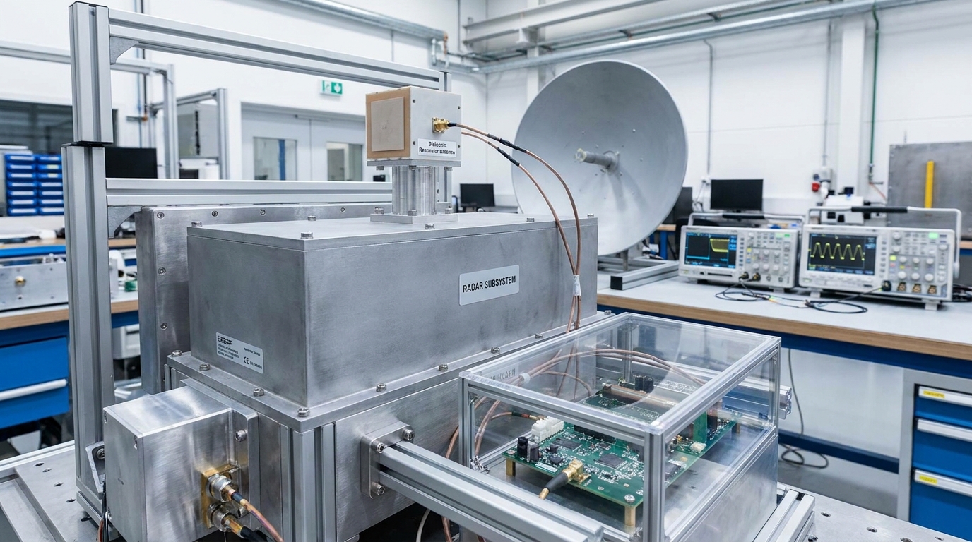
Why are they used in automotive radar sensors?
They are used in automotive radar sensors because they offer the precision and reliability needed for advanced driver-assistance systems (ADAS). You can rely on the DRA’s stable radiation pattern to accurately detect obstacles and calculate the distance of other vehicles on the road.
- Collision avoidance.
- Blind-spot monitoring.
- Adaptive cruise control.
Think about it:
The high thermal stability of ceramic means your car’s radar will work perfectly whether you are driving in a desert or in the arctic.
What are the common high frequency applications?
Common high-frequency applications include satellite-to-ground links, military surveillance, and specialized medical imaging devices. You will choose the DRA whenever you need a radiator that operates above 10 GHz with minimal energy loss.
- K-band and Ka-band SATCOM.
- Military EW systems.
- High-res imaging.
Here is the deal:
If your application requires frequencies that make standard wires look like resistors, you are in the domain of the dielectric resonator.
| Industry | Primary Use Case | Frequency Band |
|---|---|---|
| Telecom | 5G mmWave Infrastructure | 24 GHz – 39 GHz |
| Automotive | ADAS Radar Sensors | 76 GHz – 81 GHz |
| Aerospace | Satellite Data Links | 18 GHz – 40 GHz |
Compare these industries to your own project goals to see how others are leveraging ceramic technology to solve high-frequency challenges.
Key Takeaway
From 5G to self-driving cars, the DRA is the engine behind high-frequency innovation. Its unique combination of efficiency and compact size makes it the go-to solution for the most demanding RF environments in the world.
Conclusion
Understanding the technology behind the Dielectric Resonator Antenna is the first step toward building more efficient, compact, and high-performance RF systems. Whether you are designing the next generation of 5G infrastructure or a high-precision automotive radar, the move to ceramic radiators offers a clear path to overcoming the limitations of traditional metallic designs. Our vision at Corelix RF is to provide the engineering-driven hardware and validation you need to succeed in the complex world of high-frequency electronics. To learn more about how we can support your next project, contact us today for a comprehensive engineering review.
FAQ
Can I use a DRA for low-frequency applications?
Yes, but they are most efficient at high frequencies. While possible, the ceramic block would need to be very large for low frequencies, making it less practical than traditional wire antennas below 1 GHz.
What’s the best way to mount a DRA on a PCB?
Direct surface mounting is best. You should use a high-quality RF adhesive or mechanical clamping to ensure the resonator remains perfectly aligned with its feeding probe or slot.
How do I know if my material is low-loss enough?
Check the loss tangent ($\tan \delta$). For professional applications, you should look for materials with a loss tangent of less than 0.002 at your target operating frequency.
Can I build a DRA array without a phased-array IC?
Only for fixed beams. Without a dedicated phase-shifting IC, your array will have a static radiation pattern that cannot be steered electronically.
How do I choose between a rectangular and a cylindrical shape?
Choose rectangular for tuning flexibility. Rectangular DRAs allow you to adjust height, width, and depth independently to achieve your desired bandwidth and frequency, whereas cylinders are more limited.