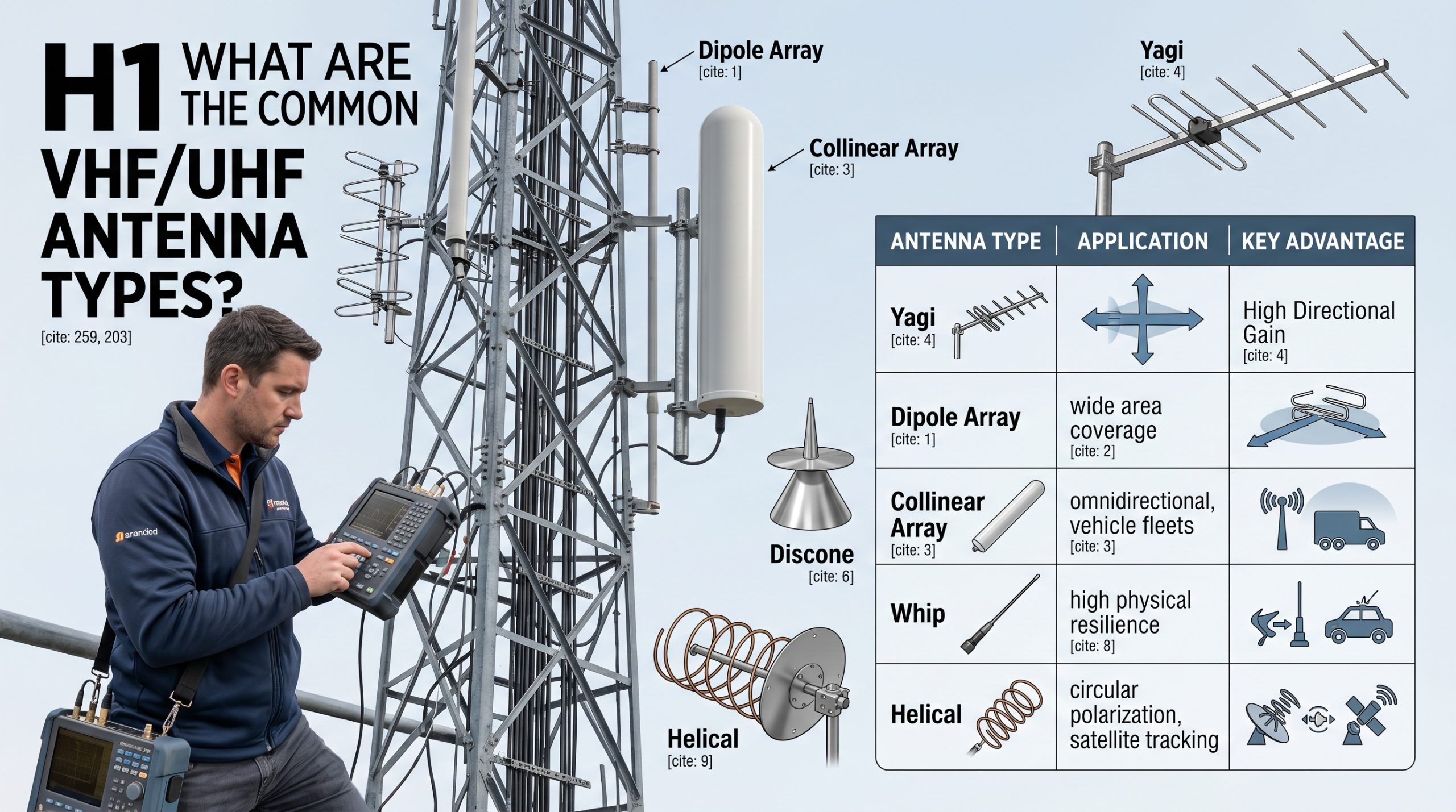
What are the common very high frequency/ultra-high frequency (VHF/UHF) [30 MHz to 300 MHz, and 300 MHz to 1000 MHz] antenna types? Various VHF/UHF models operate across modern communication networks. Specific designs include Yagi, collinear arrays, and exposed dipoles. Poor signal reception frustrates system operators everywhere. Dropped transmissions cause massive operational failures continuously. We present proven techniques offering reliable wireless connectivity. Upgrading your equipment resolves most persistent transmission hurdles.
1. What are Dipole Array Antennas?
A dipole array represents a fundamental VHF/UHF configuration utilized heavily today. Multiple separate radiating elements combine for shaping directed energy. Engineers position these components carefully alongside sturdy mounting masts. Such arrangements create powerful signal patterns predictably. Users gain significant operational advantages by stacking components vertically. Many industries rely upon these towering structures.
How do these arrays operate?
This is where things get interesting… Phased currents flow through every connected metallic element. Electromagnetic fields emerge from each separate conducting rod. These individual waves merge into one cohesive focused beam. Constructive interference amplifies signals heading toward specific target locations. Destructive interference minimizes wasted energy behind the main array.
- Spacing dictates overall radiation pattern characteristics.
- Cable lengths control individual element phasing.
- Mast proximity affects final beam shapes.
Where do engineers install them?
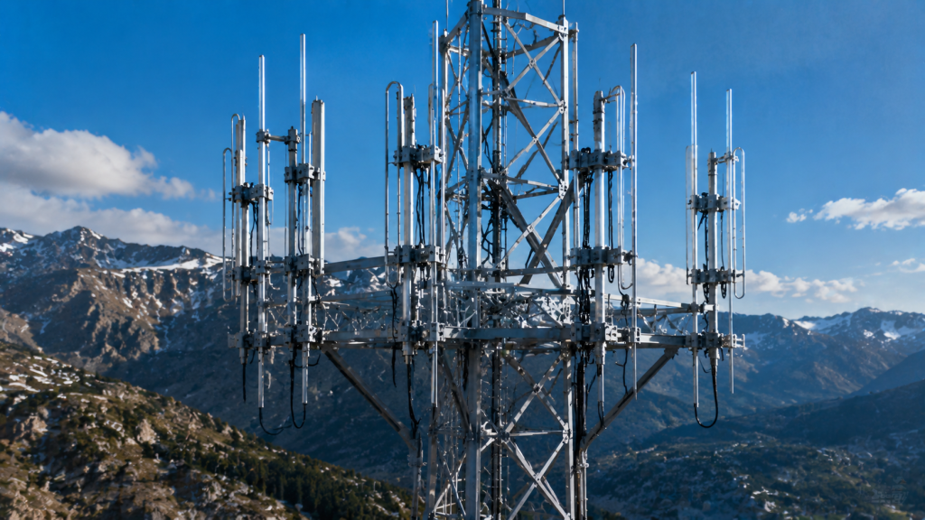
Public safety agencies deploy these units heavily across mountainous regions. Emergency dispatch centers require massive coverage areas for reliable communications. Broadcast stations utilize similar arrays for distributing television programming. High power handling makes them extremely attractive for commercial stations. Many RF power amplifier modules drive massive amounts of energy through these durable structures.
Key Takeaway: Stacked dipoles generate strong signals suitable for wide area communications.
Parameter | Description
Bandwidth | extremely wide range
Durability | high weather resistance
Pattern | directional shaping possible
Such parameters dictate best deployment strategies.
2. What are Exposed Dipole Antennas?
An exposed dipole functions as another popular VHF/UHF solution. Single radiating elements attach directly onto sturdy vertical poles. They feature incredibly rugged physical profiles without fragile plastic covers. High winds rarely damage these simple metal constructs. Operators mount them atop tall buildings seamlessly. This height provides excellent line-of-sight propagation advantages. Installation takes very little effort overall.
Why select exposed designs?
You might be wondering… Lightning strikes destroy fragile equipment frequently during heavy summer storms. Thick aluminum pipes withstand direct electrical impacts far better. Grounding becomes straightforward with all-metal mounting hardware directly touching towers. Moisture cannot accumulate inside closed radomes because none exist. No fiberglass covers exist that could crack under UV exposure.
- Technicians inspect connections visibly without special dismantling tools.
- Water sheds naturally away from critical electrical feed joints.
- Ice loading causes fewer catastrophic structural mast failures.
What radiation patterns emerge?
Single dipoles naturally push energy outward equally in free space. Mounting them near metal poles alters this behavior significantly. Reflected waves compress circular patterns into tight cardioid shapes. This pushes extra energy away from supporting mast structures. Engineers exploit this phenomenon deliberately during complex system design. They aim main beams toward highly populated urban valleys.
Key Takeaway: Exposed models offer unmatched physical resilience alongside predictable pattern shaping.
Component | Benefit
Thick Elements | survives harsh environments
Metal Mounts | simplifies lightning protection
Open Design | eliminates hidden condensation
This simplicity keeps ongoing maintenance costs extremely low.
3. What are Collinear Antennas?
Collinear arrays represent highly efficient VHF/UHF broadcast tools for flat terrain. Several half-wave dipoles stack vertically inside one protective hollow tube. This vertical arrangement squashes energy down toward the earth. Signal strength increases dramatically toward the distant horizon. Wasted energy no longer shoots up into empty space. Distant receivers experience huge connection boosts.
How do they manage phasing?
Let’s dig a little deeper… Internal delay lines connect each radiating section securely together. Phasing coils flip currents so every element radiates perfectly aligned. Without these coils, opposing waves would cancel each other out completely. Achieving perfect alignment requires precise factory manufacturing tuning. These internal components hide safely within protective fiberglass radomes.
- Protective tubes shield delicate internal wiring against weather.
- Phasing coils maintain correct signal timing between segments.
- Vertical stacking increases effective radiated power output greatly.
Who uses collinear arrays?
Amateur radio enthusiasts mount them high above residential rooftops. Cellular base stations utilize massive versions daily across global networks. Marine vessels install them atop tall shipboard masts. These users need strong signals reaching all directions equally. Such omnidirectional antennas provide full 360-degree coverage effortlessly. They serve mobile vehicle fleets traveling through large cities reliably.
Key Takeaway: Vertical stacking compresses energy horizontally for maximum omnidirectional range.
Specification | Value
Radiation | omnidirectional horizontal
Gain | increases with total length
Protection | sturdy fiberglass radome
Vertical length directly determines maximum broadcast signal reach.
4. What are Yagi Antennas?
Yagi-Uda designs serve as classic directional VHF/UHF tools. One driven element connects directly alongside your main transmitter cable. Several passive elements sit in front of this driven driver. A single reflector rod sits directly behind the driven element. This specific physical arrangement shoots energy forward like a flashlight beam. Forward gain increases tremendously using this configuration.
How do passive elements function?
Here’s a crazy thought… Unconnected metal rods actually boost signal transmission strength noticeably. The driven dipole radiates energy into nearby parasitic aluminum elements. These parasitic rods re-radiate that same energy outward immediately. Precise spacing causes forward waves to align perfectly together. Rearward waves cancel out almost completely behind the reflector.
- Directors pull radio signals strongly forward.
- Reflectors block energy traveling backward efficiently.
- Element lengths determine exact operating frequency resonance.
What makes them so popular?
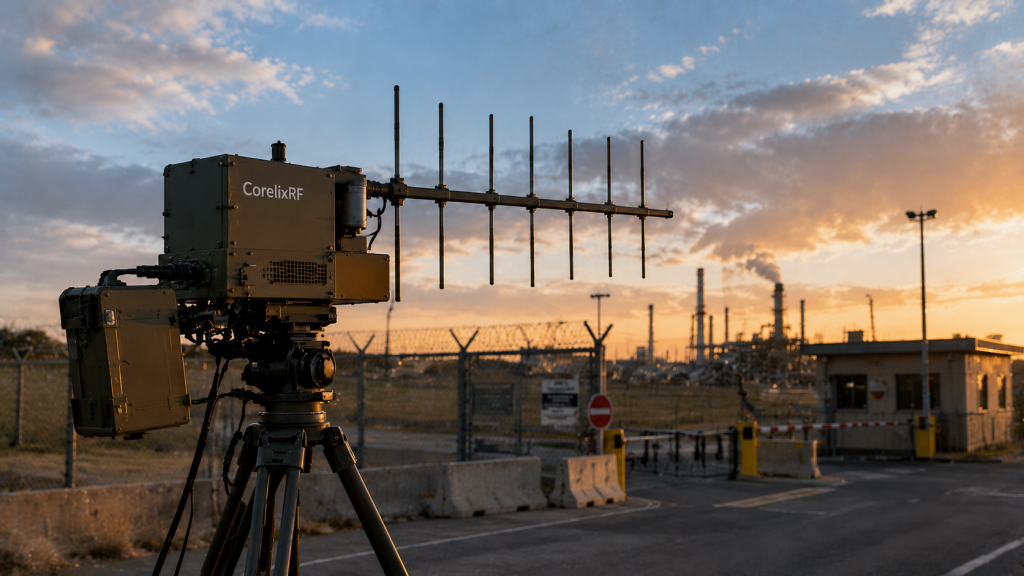
Rural homes use them for capturing weak distant television broadcasts. Point-to-point digital data links rely upon their tight focus. Wildlife trackers locate tagged animals using portable handheld versions. Their lightweight aluminum tubular construction makes aiming surprisingly easy. Many anti-drone systems pair them with powerful interference jammers. This focuses defensive electromagnetic energy squarely upon airborne targets.
Key Takeaway: Parasitic elements create highly focused beams perfect for point-to-point links.
Part | Function
Driver | connects radio cable
Reflector | blocks backward signals
Director | pulls waves forward
Adding more directors tightens forward beamwidth significantly.
5. What are Log-Periodic Antennas?
A log-periodic array functions as an exceptionally wideband VHF/UHF directional device. Multiple dipoles of increasing length sit along one central boom. Short elements sit up front while longer ones remain behind. Only a few elements operate efficiently at any given frequency. Active sections shift backward dynamically as operating frequencies decrease.
Why do engineers need them?
But wait, there’s more… Traditional Yagis only work across very narrow frequency bands. Scanning across massive spectrums requires different equipment entirely otherwise. Log-periodics cover massive ranges effortlessly without any manual adjustments. Spectrum monitoring government stations depend upon this unique capability. Military units utilize them for capturing unknown enemy transmissions quickly.
- Elements scale logarithmically along the long central boom.
- Crisscrossed feedlines connect every single individual dipole together.
- Shorter front elements intercept higher frequency waves smoothly.
How do they perform?
Gain remains surprisingly consistent across massive multi-octave bandwidths. Forward directivity resembles standard narrow directional arrays closely. They exhibit slightly less peak gain than dedicated single-band designs. However, replacing ten different models with one unit saves immense money. Testing laboratories use them inside shielded anechoic chambers routinely.
Key Takeaway: Logarithmic scaling enables consistent directional performance across massive frequency sweeps.
Trait | Performance
Bandwidth | extremely wide
Gain | moderate but stable
Size | relatively large
Wideband capabilities justify their slightly larger physical footprints.
6. What are Discone Antennas?
Discone designs offer another unique VHF/UHF wideband reception option. A flat horizontal metal disc sits directly above a hollow cone. Radio waves launch from the tiny gap between these two structures. Their unique physical geometry provides incredible electrical frequency agility. They operate smoothly across massive bands spanning several octaves. No mechanical tuning components are required whatsoever for operation.
How does the shape help?
Think about this… Sharp structural angles normally restrict operating bandwidths severely. The smooth geometric transition from disc to cone creates infinite matching possibilities. High frequencies resonate efficiently near the narrow top gap. Low frequencies push downward toward the much wider base. Electrical impedance remains stable throughout this entire sweeping range.
- The top disc acts like a fat horizontal radiator.
- The bottom cone functions as an artificial ground plane.
- Signals radiate equally in all flat horizontal directions.
Where do you find them?
Aviation control towers install them for communicating with diverse arriving aircraft. Police radio scanners utilize miniature versions for monitoring varied local channels. Automated weather monitoring stations transmit data using these reliable units. Their symmetrical vertical profiles resist heavy wind loading beautifully. They handle harsh outdoor environmental factors with graceful endurance.
Key Takeaway: Disc-and-cone geometry allows omnidirectional wideband coverage without any mechanical tuning.
Element | Shape
Top | flat circular disc
Bottom | hollow metal cone
Pattern | 360-degree horizontal
This physical geometry eliminates complex electrical matching networks completely.
7. What are Bowtie Antennas?
Bowtie models serve as simple yet effective VHF/UHF wideband receivers. Two triangular flat metal pieces meet at one central feed point. This structural shape resembles classic formal men’s neckwear exactly. Expanding the metallic surface area increases usable reception bandwidth significantly. Wire outline versions exist, but solid metal provides clearly superior performance. They sit flat against interior walls easily.

Why replace standard wires?
Ready for the good part? Thin wires only resonate properly at very specific lengths. Fat geometric conductors trick radio waves into seeing shorter paths. Triangles provide massive metallic surface areas compared to thin rods. Television viewers mount them behind modern flat screens effortlessly. They capture digital HDTV broadcasts flawlessly across entire metropolitan cities.
- Flat shapes fit inside cramped indoor living spaces easily.
- Reflective wire mesh backings push signals forward nicely.
- Connecting multiple bowties increases overall system reception gain.
Do they transmit well?
Engineers rarely use them for commercial high-power broadcasting applications. Their central feed points handle only moderate RF power levels safely. However, short-range tactical military communication gear sometimes incorporates modified versions. You can hide them inside small briefcases for covert operations. Portable SDR modules pair nicely with miniature printed circuit bowties.
Key Takeaway: Triangular elements broaden frequency response while maintaining very flat physical profiles.
Application | Suitability
TV Reception | excellent
Covert Ops | very good
High Power | poor
Broad surface areas solve many frustrating narrow bandwidth problems.
8. What are Whip Antennas?
Whip designs function as extremely flexible VHF/UHF mobile radiators. A single springy metal wire mounts vertically above some ground plane. Mobile emergency vehicles use them extensively for constant radio contact. They bend harmlessly when violently striking low hanging tree branches. A thick mounting base contains matching coils hidden from view. Installation takes merely minutes using simple hand tools.
How do they handle movement?
What’s the real story? Rigid metal poles snap rapidly under constant vehicle vibration. Flexible steel wire absorbs massive physical road shocks continuously. Spring mounts add even more physical impact resistance at their bases. Police cruisers race down bumpy highways without losing critical radio contact. The vertical upright orientation works perfectly for cars driving anywhere.
- Steel whips bend up to ninety degrees safely.
- Base coils match impedance for different mobile radio bands.
- Magnetic roof mounts allow rapid temporary vehicle fleet installations.
Do they need grounds?
Yes, a whip requires a solid metallic conductive surface underneath. Car metal roofs provide excellent artificial ground planes automatically. Handheld portable radios use the operator’s own physical body as a counterpoise. Without proper electrical grounds, transmission performance drops off a cliff. Proper physical installation guarantees strong signals reach distant repeater towers.
Key Takeaway: Flexible steel construction enables durable mobile communications across incredibly bumpy terrain.
Component | Function
Steel Wire | radiates radio waves
Spring Mount | absorbs physical impacts
Coil Base | matches electrical impedance
Vehicle roofs represent ideal mounting locations for mobile whips.
9. What are Helical Antennas?
Helical models offer unique VHF/UHF circular electromagnetic polarization capabilities. Thick conductive wire coils around a central sturdy supporting axis. They look exactly like oversized metallic industrial springs. A flat round reflector plate sits at one rear end. They shoot radio energy out like a focused twisting corkscrew. Space satellites use this twisting signal path extensively.

Why twist the signal?
This is where it gets interesting… Linear signals fade terribly when distant receivers rotate physically. Satellites tumble constantly while orbiting far above the earth. Circular polarization guarantees solid radio reception regardless of physical orientation. The twisting wave cuts through chaotic atmospheric disturbances nicely. Rain causes less signal interference compared to flat horizontal waves.
- Pitch dictates how tightly the wire wraps coils.
- Diameter controls primary operating electromagnetic frequencies.
- Reflector plates block backwards waste radiation completely.
Who utilizes helical designs?
Space agencies build massive ground arrays for tracking orbital rockets. Drone pilots use smaller portable versions for receiving continuous video feeds. Handheld security walkie-talkies cover their short helicals in flexible black rubber. These protective “rubber ducks” compress long wires into tiny spaces. They sacrifice some broadcast efficiency for extreme physical portability.
Key Takeaway: Coiled wires generate twisting signals that ignore frustrating receiver rotation issues.
Design Parameter | Effect
Coil Diameter | sets operating frequency
Coil Pitch | adjusts radiation angle
Turns Count | increases total gain
More turns create tighter beams reaching much further distances.
10. What are Loop Antennas?
Loop configurations wrap continuous conductors into full circles or squares. Small loops function as incredible magnetic field reception sensors. They ignore electrical static noise generated by nearby power lines. Large wire loops radiate strongly toward the sky for distant bounces. They fit perfectly into cramped suburban backyard spaces. Direction finding search teams spin them to locate hidden transmitters.
How do small loops work?
Let’s dig a little deeper… A large variable tuning capacitor sits opposite the feed point. This creates a high-Q resonant circuit capturing very specific frequencies. They act extremely narrow, requiring constant manual retuning when changing channels. However, this narrowness blocks overwhelming interference from loud neighboring signals. City dwellers love their tiny physical structural footprints.
- Tuning capacitors adjust resonance precisely.
- Thick copper pipes minimize internal electrical resistance losses.
- Shielded outer layers block static electricity interference completely.
Can they handle power?
Transmitting requires incredibly robust vacuum variable glass capacitors. Massive electrical voltages build up across the tuning gap during operation. Touching an active transmitting loop causes severe RF burns instantly. Despite these dangers, their reception performance in noisy environments remains unmatched. Amateurs build them using leftover hardware plumbing supplies regularly.
Key Takeaway: Magnetic loops provide excellent electrical noise rejection within highly compact physical dimensions.
Type | Characteristic
Small Loop | highly selective magnetic
Large Loop | skywave ionospheric propagation
Shielded | extreme static rejection
High voltages demand careful physical placement during any operation.
FAQ
Q1: Can I use a single model for both bands?
Yes, log-periodic and discone arrays cover massive frequency ranges simultaneously. Their unique geometries eliminate the need for mechanical tuning mechanisms across different bands.
Q2: What’s the best option for vehicle mounting?
Flexible steel whips represent the standard choice for mobile applications everywhere. They bend underneath obstacles harmlessly while using the metal roof as a ground.
Q3: How do I know if I need directional capabilities?
If your target receiver remains in one stationary location, select a Yagi array. This focuses all your transmission energy directly toward that specific distant point.
Q4: Do I require a fiberglass radome for outdoor use?
Collinear arrays usually need radomes to protect their delicate internal phasing coils. Exposed dipoles lack these sensitive internal parts and survive fine without covers.
Q5: Why do drone operators prefer helical models?
Helical arrays utilize circular polarization which prevents signal loss during steep banking maneuvers. A twisting signal penetrates complex environments better than standard linear waves.
Upgrading your communication infrastructure requires careful planning and proper equipment selection. Selecting appropriate array architecture solves most persistent range issues quickly. We build robust hardware systems handling extreme industrial conditions flawlessly. Our engineering teams provide custom configurations matching your exact operational specifications. Reach out to contact us today to discuss your next deployment. We lead the manufacturing market in delivering uncompromising tactical transmission solutions worldwide.