
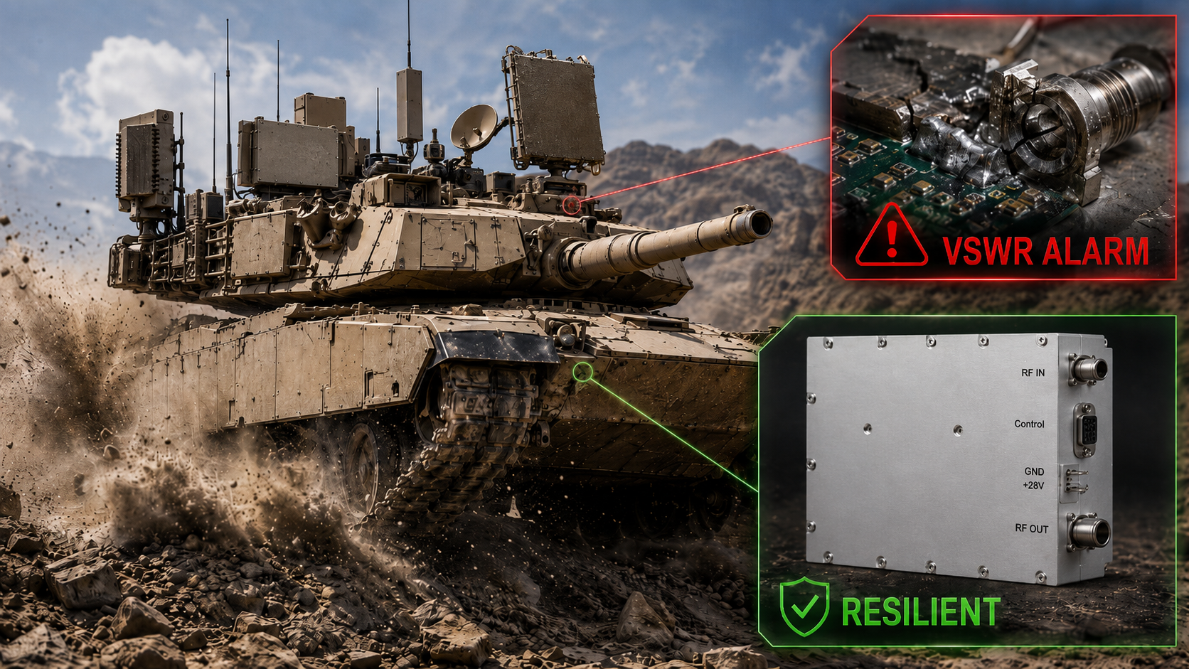
Architecture Analysis: High-Power Tracked Armor Design Essentials Against Low-Frequency Vibration. Military contractors face constant field failures regarding vehicular counter-systems. Constant mechanical shock destroys standard RF equipment rapidly. Hardware malfunctions trigger catastrophic tactical disadvantages during field deployments. We offer resilient amplifying hardware overcoming physical degradation mechanisms completely. CorelixRF delivers thirty years of manufacturing expertise resolving extreme environmental packaging defects reliably.
1. What Causes System Failures in Tracked Armor RF Applications?
Armored transport platforms generate massive kinetic energy during off-road navigation maneuvers. Heavy metal treads striking uneven terrain transmit continuous structural shock waves directly into mounted electronic racks. Engineers frequently observe sudden power drops on vehicular electronic warfare displays during field trials. But here’s the kicker those warnings usually indicate severe physical layer degradation rather than software anomalies. Operators notice sudden VSWR alerts flashing across tactical screens without obvious external damage occurring. Standard laboratory-grade amplifiers simply disintegrate under such relentless mechanical punishment within days. Printed circuit boards flex microscopically under continuous low-frequency oscillation profiles. Repeated flexing cycles fatigue copper traces alongside surface mount component terminations inevitably. Systems demand specific engineering approaches mitigating kinetic energy transfer towards delicate microwave matching networks. We analyze these failure modes through rigorous metallurgical testing procedures regularly. Analyzing physical damage reveals specific patterns directly correlating with terrain-induced shockwaves. System integrators must understand these physical limitations before designing expensive military hardware. Ignoring mechanical realities leads directly toward catastrophic mission failures under combat conditions. Our team documents these specific failure modes across hundreds of ruined third-party devices.
Tracked Vehicle Failure Modes
| Phenomenon | Physical Cause | RF System Impact |
| VSWR Alarms | Connector loosening | Reflected power spikes |
| Output Drops | Solder joint cracks | Total signal loss |
| Thermal Faults | Heat sink separation | Transistor burnout |
2. How Does Low-Frequency Vibration Destroy RF Connectors?
Threaded microwave interfaces undergo unique physical stresses aboard moving heavy cavalry units. Constant rumbling frequencies loosen coupling nuts subtly over extended deployment periods. Loose interfaces introduce microscopic air gaps between mating dielectric surfaces. What’s the real story? An improperly mated connector transforms a matched transmission line into a reactive nightmare quickly. Air gaps alter characteristic impedance dramatically at microwave frequencies. Reflected power surges backward toward active amplifying stages instantly. Engineers measuring these degraded cables observe unpredictable return loss variations during active movement. A compromised joint causes intermittent signal dropouts rendering communication links useless. Combat environments contain high humidity levels accelerating chemical degradation significantly. For example, morning dew cycles aboard desert deployment vehicles trap water inside loose junctions. We require heavy-duty fastening techniques securing every radio frequency junction permanently. Proper torque specifications combined with safety wire techniques prevent rotational uncoupling under duress. Field maintenance crews cannot constantly check every single coaxial connection during active patrols. Designing self-locking interfaces prevents this maintenance burden entirely. Our factory enforces strict mechanical tolerances eliminating threaded interface slop during manufacturing. This precision guarantees maximum contact area regardless of external vibrational frequencies.
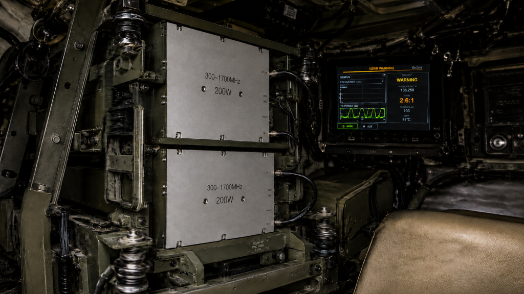
Connector Interface Degradation Matrix
| Component | Stress Factor | Consequence |
| Coupling Nut | Low-frequency rumble | Thread separation |
| Center Pin | Lateral shock | Dielectric cracking |
| Plating | Moisture ingress | Galvanic corrosion |
3. Why Do Microscopic Solder Joints Crack Under Continuous Mechanical Stress?
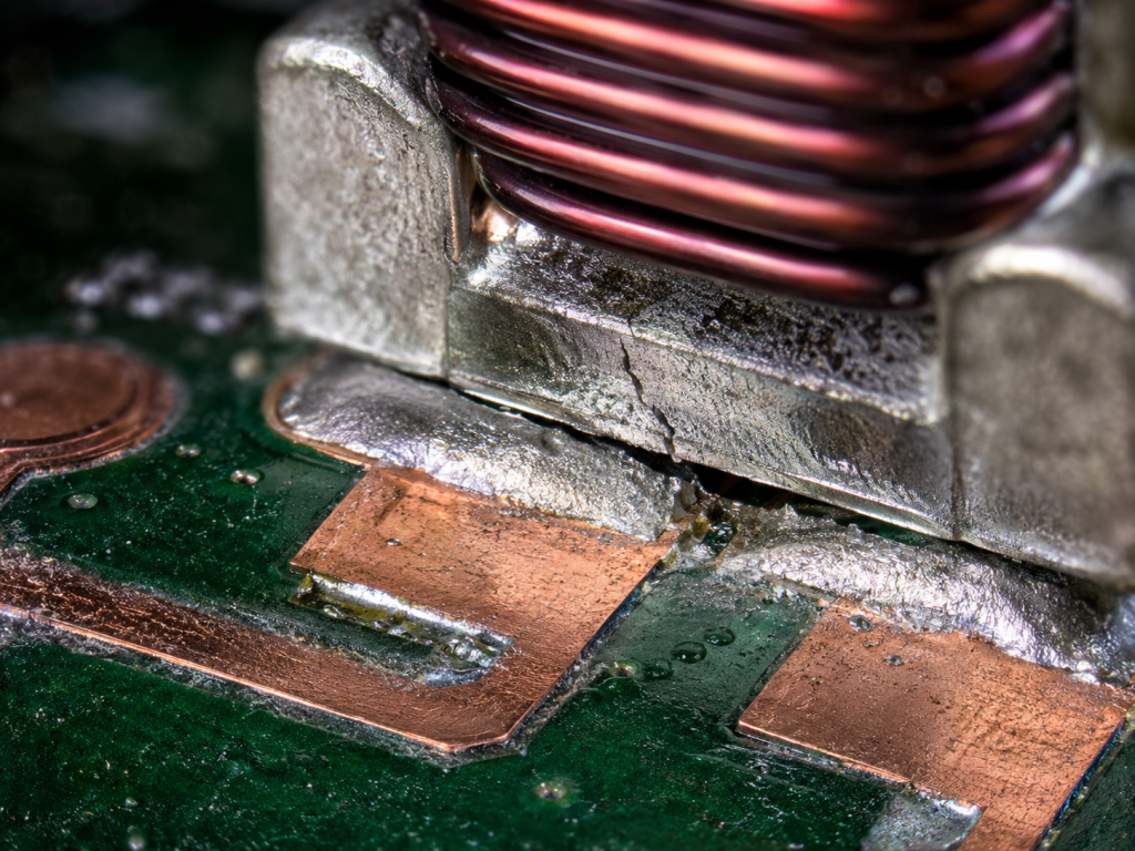
Surface mount devices sitting upon FR4 substrates experience differential thermal expansion simultaneously with kinetic shock. Heavy matching capacitors literally tear themselves away from solder pads during aggressive maneuvering. Lead-free solder alloys exhibit brittle characteristics unsuitable for extreme kinetic environments. This is where it gets interestingc microscopic fractures propagate silently through intermetallic layers before catastrophic electrical failure happens. Technicians cannot detect these hairline cracks using standard visual inspection methods. High-power transistors generate significant heat gradients compounding mechanical fatigue exponentially. Thermal cycling expands materials at different rates creating sheer forces across every soldered joint. Resonant frequencies amplify physical displacement causing component leads to snap without warning. For instance, a heavy inductor vibrating independently from its substrate shears its own mounting pads rapidly. Mitigation requires specialized dampening compounds securing large components firmly against rigid substrates. Conformally coating entire assemblies adds another layer of mechanical support against resonant destruction. We employ advanced silicone-based adhesives absorbing kinetic energy before it reaches brittle solder joints. Factory testing involves mounting circuit boards onto multi-axis shaker tables simulating battlefield conditions perfectly. Engineers monitor electrical continuity during these violent shaking tests verifying mechanical design integrity. Only designs passing these brutal validation protocols enter our standard product catalog.
PCB Mechanical Stress Factors
| Stress Type | Material Affected | Mitigation Strategy |
| Thermal Expansion | Copper traces | Matched substrates |
| Kinetic Shock | Inductors | Silicone dampening |
| Resonant Vibration | Solder joints | Conformal coating |
4. What Are The Link Budget Consequences of Undetected Impedance Mismatches?
Impedance variations ripple through entire broadcast chains causing compounding performance degradation. A cracked antenna feed introduces sudden mismatch conditions forcing final stage transistors into non-linear operation. Link margins shrink dramatically as forward transmitting power converts into wasteful thermal dissipation. Let’s look at the data return loss figures plummeting below ten decibels indicate severe operational peril. Amplifiers attempting compensation draw excessive direct current from vehicular alternators. Current spikes trip system breakers silencing defensive jamming transmitters completely. Failing this calculation leaves personnel unprotected against modern electromagnetic threats. Imagine an improvised explosive device jamming system losing fifty percent of its radiating power silently. The vehicle crew proceeds forward believing their electronic shield remains fully operational. Suddenly, external threats penetrate this weakened bubble causing devastating consequences. We prevent this scenario by over-engineering every single transmission line parameter internally. Our designs maintain strict impedance matching even under severe physical contortion. We utilize thick dielectric substrates resisting compression forces typically ruining thinner printed circuit boards. Every design choice focuses entirely upon maximizing survivability during worst-case tactical scenarios.
Link Budget Degradation Simulation
| VSWR Condition | Reflected Power | Output Status |
| 1.3:1 | Minimal | Nominal Operation |
| 2.0:1 | 11% Reflected | Safe Limit Reached |
| 5.0:1 | 44% Reflected | Imminent Failure |
5. How Does the CRF-PA-300M1700M-200W Solve Vibration-Induced Degradation?
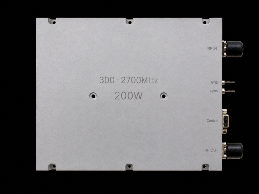
CorelixRF engineers designed specific architectural defenses mitigating kinetic damage mechanisms entirely. The CRF-PA-300M1700M-200W module covers wideband frequencies spanning 300-1,700 MHz efficiently. Delivering 200 W rated output power requires absolute mechanical stability. Ready for the good part? We utilize CNC-machined aluminum housings eliminating chassis flex completely under extreme stress. Our factory secures internal printed circuit boards using high-density mounting screw patterns. Dense fastening intervals shift mechanical resonance points far above typical tracked vehicle vibration profiles. Engineers apply specialized microwave adhesives anchoring heavy inductive components securely against substrate movement. These techniques prevent component detachment despite continuous exposure toward brutal operational environments. Solid-state transistors sit directly upon massive copper heat spreaders minimizing thermal expansion differentials. This architecture guarantees reliable transmission capabilities supporting critical vehicular defense missions. Furthermore, we eliminate flexible coaxial jumpers internally whenever physically possible. Rigid microstrip lines route signals directly between transistor stages without vulnerable wire connections. These solid copper traces cannot shake loose regardless of external kinetic punishment. We also plate these traces using heavy gold over nickel preventing oxidation during extended shelf lives. Field technicians appreciate equipment functioning perfectly after sitting inside humid storage depots for years. Our factory calibrates every single unit individually verifying performance parameters before final sealing. We understand military procurement demands absolute perfection from every delivered component.
6. What Role Does Structural Integrity Play in the 200W Amplifier Design?
Physical packaging dictates electronic survivability during aggressive cross-country transit operations. The hardware package size measures exactly 200\158\25 mm maintaining a low geometric profile. Compact dimensions reduce rotational moment arms minimizing sheer forces acting upon mounting brackets. Why does this matter? A smaller physical footprint resists low-frequency resonance significantly better than large enclosures. Weighing strictly 1.4 kg prevents excessive stress upon vehicular equipment racks. We implement air cooling methods utilizing external fans pushing high-velocity ambient streams across fins. Thermal management remains mandatory since high internal temperatures accelerate material fatigue rapidly. Our mechanical outline drawing provides clear integration references for precise mounting hole alignment. System integrators use these specific dimensional reviews confirming exact placement within tight compartments. Robust structural design forms an impenetrable shield protecting sensitive high-frequency microelectronics inside. Our factory machines these specific enclosures from solid aluminum billets maximizing tensile strength. We avoid cheap cast metal housings containing microscopic voids which fracture under sudden impacts. Massive mounting flanges distribute mechanical loads evenly across wide vehicle bulkhead surfaces. Technicians securing these heavy flanges create an incredibly rigid bond preventing independent chassis resonance. We also integrate heavy ground lugs directly into these machined blocks ensuring solid electrical returns. This unified mechanical approach solves thermal dissipation and kinetic vibration problems simultaneously. Equipment survival demands uncompromising metalwork framing delicate semiconductor payloads securely.
7. How Do Connectors Like SMA-KFD46 and N-Female Withstand Tracked Vehicle Abuse?
External interfaces represent primary failure points aboard mechanized combat platforms. We select RF IN connectors utilizing rugged SMA-KFD46 variants specifically. Output stages demand N-Female connectors handling continuous two hundred watt carrier waves safely. Here is the secret these specific connector types feature extended threading engagements resisting vibration-induced loosening. Thick metal flanges secure N-type receptacles firmly against thick aluminum chassis walls. This prevents mechanical stress from transferring directly into internal coaxial assemblies. SMA-KFD46 input ports feature specialized dielectric materials maintaining dimensional stability across wide temperature variations. Technicians applying proper torque wrenches ensure these junctions remain sealed against moisture intrusion. Control signals pass through standard DB9 interfaces allowing secure screw-locking attachment mechanisms. Every physical port prioritizes mechanical locking features over quick-disconnect convenience for maximum field reliability. We source these specific connectors from certified military-grade suppliers maintaining strict metallurgical controls. Cheap commercial connectors utilize inferior brass alloys bending easily beneath heavy coaxial cables. Our selected interfaces employ hardened stainless steel bodies resisting deformation completely. Internal center pins feature thick gold plating maintaining low contact resistance despite repeated mating cycles. Field operators routinely connect heavy test equipment directly onto these ports during diagnostic checks. We engineered these junctions handling significant lateral loads without internal dielectric cracking. Rugged external interfaces protect delicate internal microstrip networks from accidental human damage.
8. Why Are Stable Electrical Characteristics Necessary for Vehicular Counter-Systems?
Electronic warfare demands absolute signal fidelity regardless of external environmental chaos. Our hardware maintains nominal gain around 53 dB continuously. Gain flatness stays strictly 1.8 dB ensuring equal power distribution across wide bandwidths. Now consider this unstable gain profiles cause unpredictable jamming coverage leaving vehicles exposed momentarily. Input drive levels for rated output require merely 0 dBm up through 8 dBm. Harmonic distortion remains exceptionally low, typically around -12 dBc preventing interference alongside friendly communications. Spurious emissions stay suppressed below -60 dBc maintaining clean spectral footprints. Input VSWR measures typically 1.3:1 preventing dangerous reflections toward preceding driver stages. Output VSWR withstands ratios reaching 2.0:1 accommodating fluctuating antenna impedances during transit. Operating temperatures spanning -40 to +85 °C cover extreme global deployment scenarios flawlessly. Consider a desert patrol where internal vehicle cabin temperatures reach blistering levels by mid-afternoon. Our hardware continues amplifying signals cleanly without engaging thermal shutdown protection prematurely. Conversely, arctic deployments subject equipment toward freezing conditions shrinking internal materials significantly. We select specialized substrate materials matching thermal expansion coefficients perfectly with surrounding copper traces. This careful material science prevents trace delamination during rapid temperature fluctuations. Operators rely upon predictable microwave generation regardless of external weather conditions. We deliver consistent engineering truth validating every parameter through rigorous environmental chamber testing.
CorelixRF Electrical Parameters
| Parameter | Typ Value | Max Value |
| Gain | 53 dB | 54 dB |
| Input VSWR | 1.3:1 | $\le1.8:1$ |
| Spurious | – | $\le-60$ dBc |
9. How Do We Implement Proper Power Supply Architecture for 28VDC Systems?
Vehicular electrical grids present notoriously noisy environments filled with massive voltage transients. Amplifying circuits require clean direct current maintaining stable RF carrier generation continuously. Our architecture operates utilizing standard 28 VDC supply voltage buses typically found onboard armored vehicles. You might be wondering how much power does a two hundred watt transmitter consume? Current consumption remains strictly 29 A during saturated continuous wave operation. Engineers must specify heavy-gauge wiring harnesses minimizing resistive voltage drops across long vehicle runs. Proper decoupling networks sit directly behind our DC input pins filtering alternator whine effectively. Massive storage capacitors provide instant energy reserves during sudden pulse-modulation demands. Grounding paths require thick braided straps terminating directly onto bare metal chassis points. Poor grounding introduces ground-loop interference destroying delicate signal-to-noise ratios instantly. Our module features integrated reverse polarity protection saving internal circuits from accidental miswiring. Field mechanics swapping vehicle batteries under fire sometimes reverse terminal connections inadvertently. We engineered protective diodes blocking destructive reverse currents completely during these chaotic moments. Furthermore, internal switching regulators operate far outside our primary communication bands. This prevents internal power supply noise from modulating main radio frequency carrier waves. Clean power yields clean spectrum, a mandatory requirement for modern digital battlefield communications. We guarantee continuous power delivery through oversized traces handling massive current surges safely.
10. What Are The Best Practices for Integrating This RF Module Into Armored Systems?
Successful field deployment relies entirely upon correct mechanical and electrical installation procedures. Technicians must mount these modules using all provided fastening locations simultaneously. Applying high-quality thermal conductive compounds between our flat baseplate and vehicle bulkheads remains mandatory. Listen to this trapped air pockets destroy thermal transfer causing rapid catastrophic semiconductor failure. Coaxial cables require adequate strain relief loops preventing tension transfer into N-Female bulkheads. Routing DC power lines away from sensitive microwave feedlines prevents cross-coupling interference effectively. System designers should monitor DB9 control pins continually for internal temperature and forward power telemetry. Integrating specific shock mounts beneath equipment racks adds secondary isolation against track-induced vibrations. CorelixRF engineering teams provide feasibility reviews within 48 hours evaluating custom integration plans. Following these strict engineering guidelines guarantees maximum lifespan for expensive defense electronics. We recommend implementing scheduled maintenance routines checking mounting bolt torque values quarterly. Operators should monitor reflected power telemetry constantly identifying antenna damage immediately upon occurrence. Our modules survive temporary high-VSWR events, but prolonged operation under severe mismatch degrades transistor longevity. We provide comprehensive troubleshooting manuals detailing exact diagnostic steps utilizing standard field oscilloscopes. Training military technicians properly ensures our hardware delivers decades of reliable tactical service. Building invincible RF systems requires active partnership between factory engineers and frontline integrators. We stand ready delivering physical hardware alongside deep integration knowledge.
Conclusion
Tracked armor deployments destroy fragile electronics through relentless kinetic force constantly. Mitigating low-frequency vibration demands ruggedized architectures featuring secure connectors alongside reinforced internal components. We strongly advise replacing commercial grade hardware utilizing our resilient CRF-PA-300M1700M-200W transmitting module immediately. Contact our factory engineers requesting complete environmental validation data sets supporting your specific project review.
FAQ
Q1: What causes system failures in tracked armor RF applications?
Continuous kinetic energy from vehicle treads breaks microscopic solder joints and loosens threaded RF connections.
Q2: How does the CRF-PA-300M1700M-200W solve vibration-induced degradation?
We use CNC-machined housings, dense screw patterns, and specialized microwave adhesives preventing internal component movement.
Q3: What role does structural integrity play in the 200W amplifier design?
Compact dimensions measuring 200\158\25 mm minimize rotational moment arms reducing sheer stress.
Q4: How do connectors like SMA-KFD46 and N-Female withstand tracked vehicle abuse?
They feature deep thread engagements resisting rotational uncoupling while preventing stress transfer into coaxial assemblies.
Q5: Why are stable electrical characteristics necessary for vehicular counter-systems?
Consistent 53 dB gain ensures reliable jamming coverage without dropping protective shields during aggressive maneuvers.
Authorized RF engineering and compliance review
For regulated RF systems, this page should be used as an engineering and compliance review path, not as a public deployment checklist. CorelixRF starts with authorization status, operating region, frequency plan, output limit, antenna interface, safety controls, thermal limits and acceptance documents.
- RFQ checklist – send the data buyers usually forget, including band, power, duty cycle, interface and test standard
- delivery documentation – check what documents can support incoming inspection, FAT review and long-term maintenance
- quality and certification review – review the quality and compliance evidence before the project moves into procurement
- RF front-end platform – compare the RF chain as a system instead of selecting one isolated module
- RF configurator – turn frequency, power, thermal and interface requirements into a first configuration brief
- case studies – review similar engineering paths before sending an RFQ
- engineering contact – send the application notes, block diagram or target specification to engineering sales
This keeps the discussion inside lawful, authorized RF programs while still giving procurement teams a clear way to request amplifier, antenna, SDR source, documentation and factory review.