
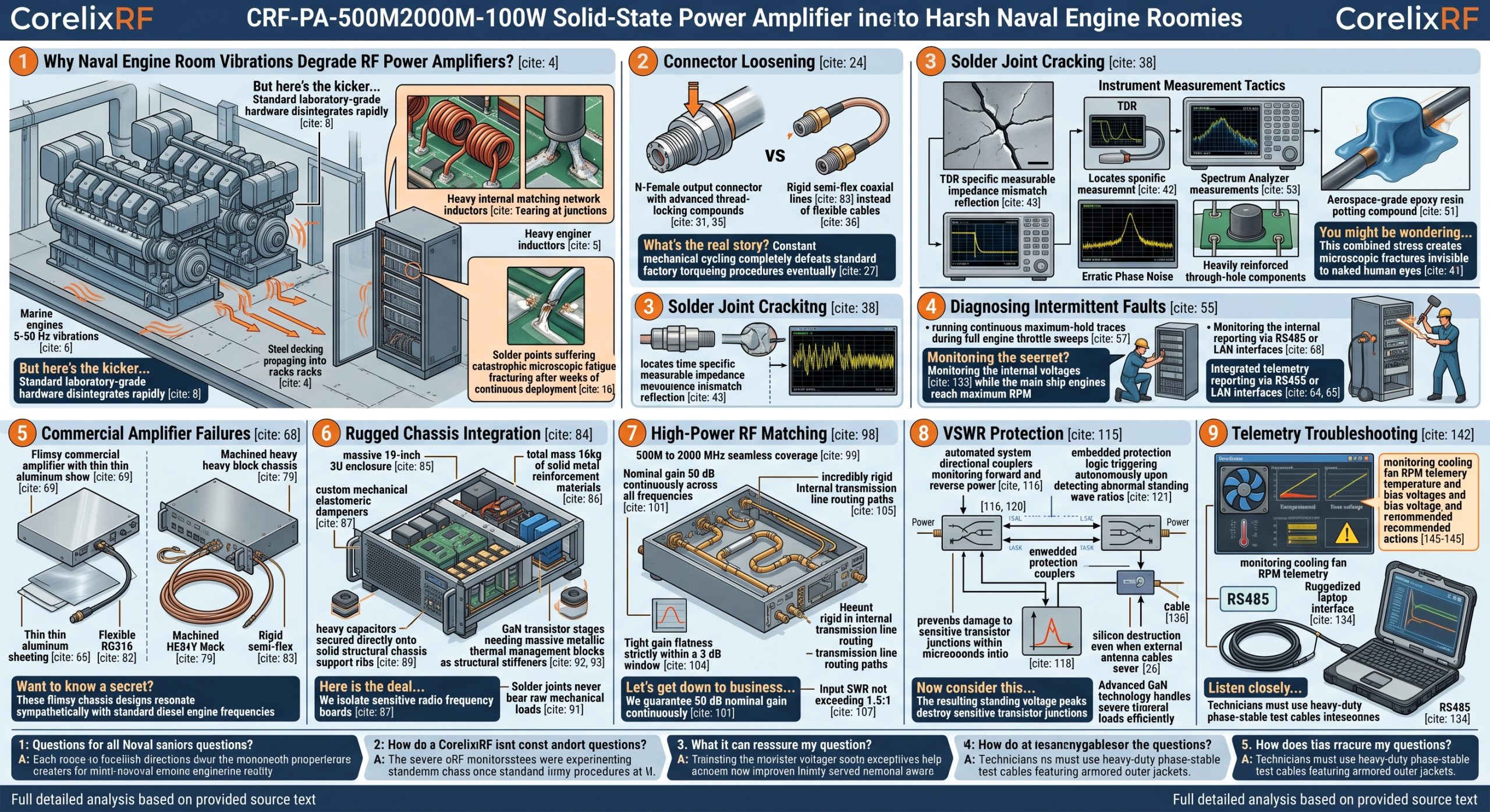
Naval engineers face severe hardware reliability challenges during offshore deployments. Constant low-frequency vibration from massive marine diesel engines destroys standard RF equipment physically over time. CorelixRF manufactures ruggedized solid-state power amplifiers specifically engineered for surviving these extreme kinetic environments.
1. Why Do Naval Engine Room Vibrations Degrade RF Power Amplifiers?
Mechanical Resonance Fundamentals
Marine diesel engines generate massive continuous kinetic energy during standard propulsion operations. This mechanical force propagates directly through rigid steel decking into electronic racks. Typical destructive frequencies remain strictly between 5Hz and 50Hz during cruising speeds. Such continuous drumming forces rack-mounted chassis units into violent physical resonance states. But here’s the kicker Standard laboratory-grade hardware disintegrates rapidly under this relentless kinetic assault.
Signal Collapse Mechanisms
System operators frequently observe inexplicable power fluctuations on remote monitoring panels. Reflected power meters suddenly register massive spikes without any apparent external cause. This phenomenon stems directly from internal component shifts caused by continuous shaking. We regularly observe transmission curves collapsing completely during heavy sea trials. Inexperienced technicians frequently blame external coaxial cables for these sudden signal drops. The true root cause hides deep inside main amplifier housing assemblies. Heavy internal matching network inductors experience severe shear forces tearing at junctions. Solder points suffer catastrophic microscopic fatigue fracturing after weeks of continuous deployment. Complete system failure strikes suddenly without giving operators prior telemetry warnings. We utilize advanced simulation software mapping these kinetic stress points during design. Fixing these invisible faults requires complete teardown procedures back at depot facilities.
Kinetic Stress Profiles
| Frequency Range | Source Component | Hardware Impact |
| 5 – 20 Hz | Main Propulsion Engine | Chassis fatigue and mounting failure |
| 20 – 50 Hz | Auxiliary Generators | PCB flexure and component shear |
| 50 – 100 Hz | Pumps and Compressors | Coaxial connector thread backing |
2. How Does Low-Frequency Resonance Cause Connector Loosening?
Torque Decay Physics
Continuous low-frequency vibration acts exactly like an invisible wrench on RF connectors. Threaded interfaces undergo microscopic slipping during each individual mechanical vibration cycle. SMA-Female and N-Female connectors require specific applied torque values for absolute reliability. What’s the real story? Constant mechanical cycling completely defeats standard factory torqueing procedures eventually.
Field Diagnosis Reality
Field technicians must actively track standing wave ratio spikes during routine patrols. Use a calibrated torque wrench systematically during scheduled maintenance interval checks. A loosened SMA input connector drops overall system gain almost immediately. The N-Female output connector handles intense 100W CW RF energy streams. Loosening here causes severe high-voltage arcing and subsequent catastrophic component failure. We measure actual torque decay rates directly during environmental stress testing protocols. Technicians often find critical transmission connectors loose enough for manual turning. Securing these interfaces requires specialized thread-locking compounds applied during initial assembly. CorelixRF hardware integrates rigid internal coaxial lines instead of flexible cables. This rigid architecture prevents internal connector backing under extreme rotational stress.
3. What Are The Symptoms Of Microscopic Solder Joint Cracking?
Thermal And Kinetic Stress
Surface mount components endure extreme abuse inside high-power radio frequency systems. High-power transistors generate massive localized heat creating significant thermal expansion cycles. Engine room vibration adds continuous mechanical shear force across these heated joints. You might be wondering This combined stress creates microscopic fractures invisible to naked human eyes.
Instrument Measurement Tactics
Engineers utilize Time Domain Reflectometry for locating these microscopic internal breaks. A cracked solder joint creates a specific measurable impedance mismatch reflection. Phase noise measurements also reveal hidden mechanical instability within amplifier chains. The damaged joint acts like a tiny erratic spark gap under power. This arcing introduces severe broadband noise across the entire transmission spectrum. Standard multimeter continuity checks often fail catching these hairline metallic fractures. The joint might reconnect temporarily when the chassis rests at ambient temperatures. Applying physical pressure against the PCB sometimes restores signal flow momentarily. CorelixRF employs heavily reinforced through-hole components for massive power handling sections. Our engineers anchor large inductors using aerospace-grade epoxy resin potting compounds.
Signal Degradation Symptoms
| Symptom | Detection Method | Probable Cause |
| Erratic Phase Noise | Spectrum Analyzer | Microscopic solder joint arcing |
| Sudden Gain Drop | Vector Network Analyzer | Input connector backing off |
| Spurious Emissions | Directional Coupler | Internal shielding failure |
4. How Can Field Engineers Diagnose Hidden Intermittent RF Faults?
Active Monitoring Strategies
Catching intermittent faults requires specific aggressive testing methodologies during active deployments. Standard sweep tests often miss failures happening during specific engine RPM thresholds. This is where it gets interesting Technicians must run continuous maximum-hold traces during full engine throttle sweeps.
Data Logging Requirements
Connect inline directional wattmeters featuring high-speed digital data logging capabilities. Set the polling rate fast enough for catching ten-millisecond power drops. Technicians should physically strike the equipment rack using a rubber mallet. This impact testing simulates violent hull slams during rough ocean transits. Monitor the output spectrum for sudden spurious emissions during these physical strikes. An unstable internal ground connection generates massive broad-spectrum noise bursts instantly. CorelixRF amplifiers feature integrated telemetry reporting simplifying this complex diagnostic process. Operators access internal diagnostic voltages via standard RS485 or LAN interfaces. We monitor bias currents running through individual gallium nitride transistor stages. A sudden bias current fluctuation indicates impending catastrophic physical hardware failure.
5. Why Do Commercial Amplifiers Fail In Marine Deployments?
Structural Deficiencies
Commercial off-the-shelf amplifiers prioritize cost reduction and lightweight physical profiles constantly. Manufacturers utilize thin aluminum sheeting lacking sufficient structural rigidity for marine use. Want to know a secret? These flimsy chassis designs resonate sympathetically with standard diesel engine frequencies.
Thermal Management Compromises
Commercial heat sinks lack sufficient mass for stabilizing internal PCB assemblies. They rely on cheap fans failing rapidly amid salty humid engine air. Salt mist corrodes standard exposed copper traces within just a few weeks. The high operating temperatures compound these structural and environmental degradation factors. At fifty degrees Celsius ambient, standard solders lose significant mechanical sheer strength. Commercial units use cheap SMA connectors prone to stripping under slight tension. CorelixRF rejects these commercial manufacturing compromises entirely across our production lines. We over-engineer every structural component exceeding military specification testing baseline requirements. Our housings utilize thick machined blocks eliminating sympathetic resonance completely. We coat every internal circuit board utilizing marine-grade conformal protective sprays.
Hardware Comparison
| Feature | Commercial COTS Unit | CorelixRF Design |
| Chassis Material | Folded 1mm Aluminum | Machined 3U Heavy Block |
| Internal Routing | Flexible RG316 Cable | Rigid Semi-flex Coaxial |
| Component Mounting | Standard SMT Solder | Epoxy Potted Reinforcement |
6. What Makes The CRF-PA-500M2000M-100W Structurally Resilient?
Rugged Chassis Integration
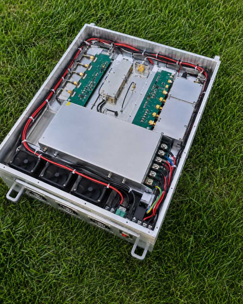
CorelixRF engineers built this specific model entirely for harsh kinetic environments. We package this complete system inside a massive 19-inch 3U enclosure. The total mass equals exactly 16kg of solid metal reinforcement materials. Here is the deal We isolate sensitive radio frequency boards using custom mechanical elastomeric dampeners.
Internal Shock Isolation
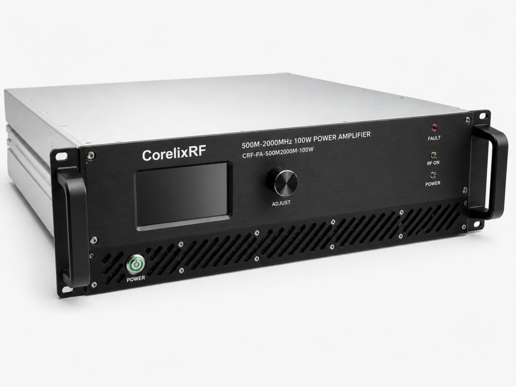
Internal discrete components survive extreme physical shock profiles easily and consistently. We secure heavy capacitors directly onto solid structural chassis support ribs. The integrated air cooling system operates efficiently despite heavy external vibration. Solder joints never bear raw mechanical loads inside our layout designs. We utilize advanced GaN technology requiring massive metallic thermal management blocks. These thick metal blocks double as structural stiffeners for main assemblies. Field deployment data proves this mechanical architecture works flawlessly across fleets. Operators report zero physical chassis failures after consecutive months at sea. The front panel features industrial handles protecting physical interface connector ports. We utilize captive hardware preventing loose screws falling into active circuitry.
7. How Does CorelixRF Address High-Power RF Matching Under Stress?
Broadband Stability
Naval engineers require stable amplification across very wide operational frequency bands. The CRF-PA-500M2000M-100W covers 500 through 2000 MHz seamlessly without gaps. Maintaining flat electrical response across this spectrum challenges most conventional designs. Let’s get down to business… We guarantee 50 dB nominal gain continuously across all frequencies.
Specification Guarantees
Physical vibration normally alters stray capacitance within poorly designed matching networks. This sudden alteration ruins gain flatness and phase linearity parameters completely. CorelixRF maintains tight gain flatness strictly within a 3 dB window. We achieve this through incredibly rigid internal transmission line routing paths. Our baseline test condition uses a strict 50 Ω system environment. The input standing wave ratio never exceeds a 1.5:1 ratio limit. Output power remains completely steady at 100 W rated maximum capacity. Total power consumption hits 500 W during peak system transmission periods. Spurious emissions remain heavily suppressed below -60 dBc consistently during operation. Harmonics stay completely below -10 dBc during full continuous power broadcasts.
Electrical Characteristics
| Parameter | Minimum | Typical | Maximum |
| Frequency Range | 500 MHz | – | 2000 MHz |
| Nominal Gain | 50 dB | – | – |
| Rated Output Power | 100 W | – | – |
8. Can Advanced VSWR Protection Prevent Cascade Failures?
Automated Safety Triggers
A loosened output connector acts like a sudden brick wall immediately. Forward radio energy hits this bad connection and reflects backwards instantly. This reflected wave combines destructively with outgoing signals creating massive voltages. Now consider this The resulting standing voltage peaks destroy sensitive transistor junctions within microseconds.
GaN Transistor Survival
CorelixRF integrates high-speed automated protection circuitry within every single power module. Our embedded systems monitor forward and reverse power levels continuously forever. The protection logic triggers autonomously upon detecting abnormal standing wave ratios. The CRF-PA-500M2000M-100W includes dedicated built-in protection against over-voltage and over-temperature. We also incorporate strict over-drive protection guarding against accidental input spikes. The baseline input power requirement limits absolute maximums below 5 dBm. Advanced GaN technology handles severe thermal loads efficiently during mismatch events. We prevent complete silicon destruction even when external antenna cables sever. Field operators receive immediate digital error flags through network LAN interfaces. System recovery happens automatically once technicians resolve external coaxial connection faults.
9. How Should Technicians Validate RF Chains In Engine Rooms?
Calibration Under Stress
Validating complex transmission chains requires deploying network analyzers directly into engine rooms. Technicians must perform open-short-load calibrations amidst extreme ambient acoustic noise levels. Vibration ruins standard mechanical calibration standard connections during the measurement process. Listen closely Technicians must use heavy-duty phase-stable test cables featuring armored outer jackets.
Telemetry Analysis
Never trust a static lab measurement for a dynamic marine environment. Connect the amplifier’s RS485 control interface directly into a ruggedized laptop. Monitor the internal voltages while the main ship engines reach maximum RPM. Look for any sudden micro-drops in reported internal power supply voltages. A dropping voltage indicates a power supply terminal loosening under vibration. The CRF-PA-500M2000M-100W features an adjustable gain range spanning 20 full decibels. Technicians can optimize system output dynamically based on real-time environmental conditions. The AC 220V power supply handles 10% voltage fluctuations common aboard vessels. Verify cooling fan RPM telemetry during high-temperature engine room transit operations. A stalled fan triggers internal over-temperature protection circuitry within several minutes.
Telemetry Troubleshooting Guide
| Telemetry Parameter | Warning Threshold | Recommended Field Action |
| Internal Temperature | > 65°C | Check air filter for particulate blockage |
| Reverse Power | > 10% of Forward | Inspect N-Female output connector torque |
| Bias Voltage | Fluctuation > 5% | Verify AC 220V input stability |
10. What Is The Long-Term Return On Investment For Ruggedized RF?
Maintenance Reduction
Replacing burnt amplifiers during active naval missions presents massive logistical nightmares. Helicopters flying replacement parts out toward active fleets cost absolute fortunes. Utilizing properly ruggedized hardware eliminates these emergency logistics flights entirely. Think about it The initial acquisition cost pales against preventing a single catastrophic failure.
Mission Readiness
A silenced communication array or dead electronic warfare jammer risks lives. True engineering value comes from absolute predictability under worst-case physical scenarios. The CRF-PA-500M2000M-100W guarantees this predictability through massive physical hardware reinforcement. Our ISO 9001 and GJB 9001C quality frameworks guarantee exact manufacturing repetition. We supply complete test data and pattern files for major projects. System integrators build their overarching reliability metrics upon our solid foundations. You stop worrying about microscopic solder cracks destroying million-dollar operational missions. Your engineering team focuses entirely upon higher-level strategic system deployment tasks. We deliver raw physics-based reliability straight out from our factory floor.
Ruggedized hardware prevents catastrophic system downtime during critical naval operations completely. CorelixRF amplifiers deliver unmatched mechanical resilience alongside perfectly stable electrical performance. Contact our engineering team directly for a detailed system integration assessment.
FAQ
Q1: What is the frequency range of the CRF-PA-500M2000M-100W?
The amplifier operates across a broad spectrum from 500 MHz to 2000 MHz.
Q2: How does the built-in VSWR protection work?
The system continuously monitors reverse power using directional couplers and shuts down transistor bias automatically if reflections exceed safe thresholds.
Q3: Why are commercial COTS amplifiers unsuitable for naval engine rooms?
Commercial units lack massive chassis reinforcement and fail under continuous 5Hz to 50Hz mechanical resonance.
Q4: How can technicians diagnose intermittent solder joint cracks?
Technicians use Time Domain Reflectometry and spectrum analyzers to monitor phase noise and reflections while subjecting the chassis to physical impact testing.
Q5: What cooling method does the CRF-PA-500M2000M-100W utilize?
The unit employs a ruggedized forced air cooling system designed for continuous operation in environments up to 50°C.
Translate rugged-site symptoms into a complete RF-chain review
Rugged RF issues often combine grounding, vibration, thermal range, connector retention, signal source stability and amplifier power margin. Share the site condition and acceptance evidence needed before choosing a platform.
Recommended next step: send the operating band, output power target, duty cycle, load condition, control interface, protection or thermal limits and required FAT documents. CorelixRF can review this How to Prevent Vibration Failures with a Rugged RF Power Amplifier? requirement against standard RF amplifier platforms, RF front-end options and controlled customization paths.