
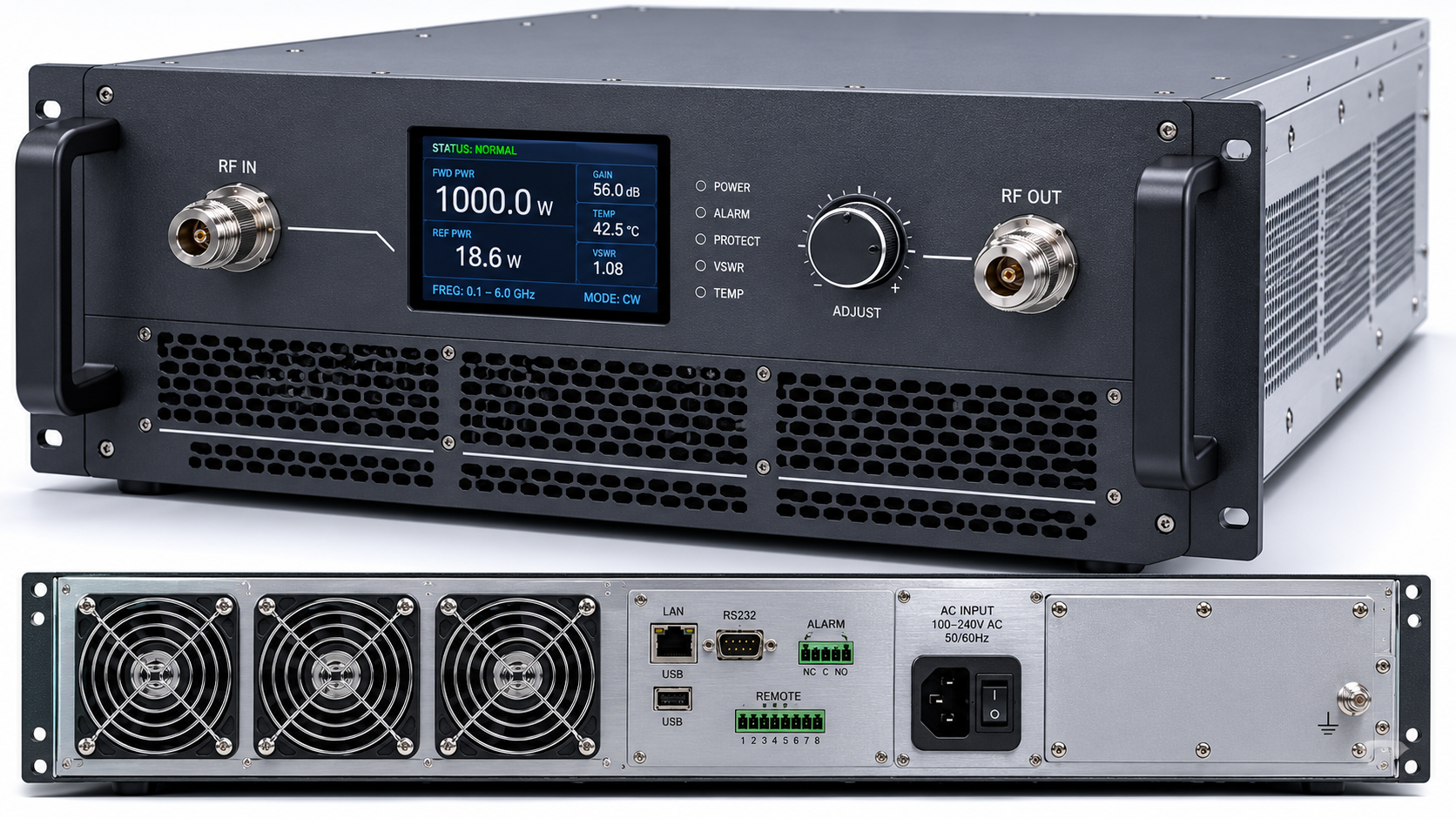
Signal anomalies plague naval engine rooms constantly. Intermittent drops disrupt primary communication arrays. Field data proves mechanical resonance destroys standard radio frequency physical layers. We isolate these failures using specific diagnostic matrices. Solid hardware architecture solves this chronic physical degradation. Here is the deal, relying on theoretical data sheets fails when marine diesel engines transmit massive kinetic energy directly into electronic chassis components.
1. Why Do Signal Anomalies Occur in Naval Engine Rooms?
Engine rooms present a unique mechanical interference profile. Massive diesel generators and turbine shafts operate continuously. They generate sustained low-frequency vibrations ranging from 10 to 50 Hz. This specific frequency band creates destructive harmonic resonance within standard equipment racks. RF systems mounted near these mechanical giants absorb continuous kinetic stress. What is the real story? The physical connections simply vibrate apart. Coaxial connectors slowly unthread. Internal Printed Circuit Board components experience shear forces. Continuous microscopic movement weakens standard solder profiles. Temperature cycling from engine heat exhaust further expands and contracts different metal alloys. These alternating thermal and mechanical loads eventually crack rigid junctions. Engineers observing remote monitors see sudden power drops. They assume electronic component failure. Reality points directly toward mechanical separation. A fractured solder point acts as a variable capacitor. It shifts impedance wildly during operation. Signal reflections travel back down the transmission line. These reflections trigger hardware self-preservation modes. Power output drops dramatically. The system goes dark momentarily.
Troubleshooting Phase Constraints | Environmental Factor | System Impact
Sustained 10-50 Hz Vibration | Physical rack resonance | Connector thread back-off
Thermal Cycling (20°C – 60°C) | Metal expansion/contraction | Solder joint fatigue
High Ambient Humidity | Condensation on exposed metal | Rapid oxide layer formation
Salt Fog Exposure | Galvanic corrosion | Ground plane degradation
2. How Does Low-Frequency Vibration Degrade RF Performance?
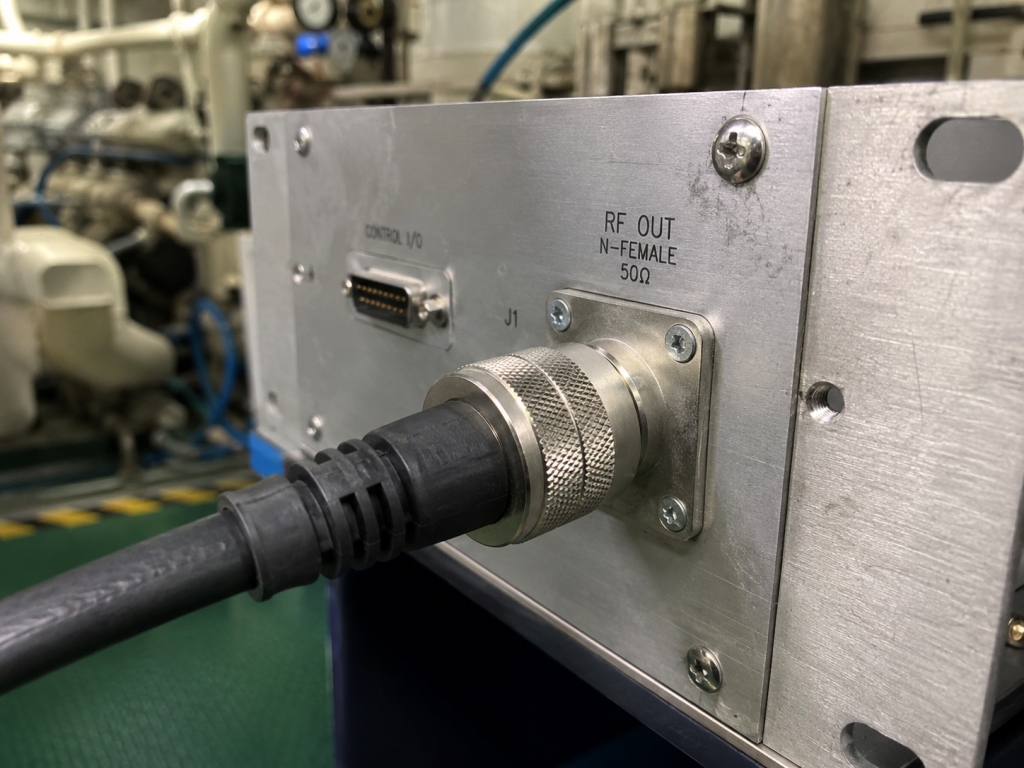
Low-frequency vibration attacks structural integrity mercilessly. An N-Female connector requires specific torque specifications for reliable mating. Continuous 30 Hz hull vibration acts like a microscopic wrench. It slowly loosens coupling nuts over several weeks. A loose connector introduces an immediate air gap. Air possesses a different dielectric constant than Teflon or air-spaced coaxial lines. Think about it, an air gap creates an abrupt impedance mismatch. This mismatch causes immediate signal reflection. Voltage Standing Wave Ratio spikes occur instantaneously. Internally, large surface-mounted components suffer similar fates. Heavy inductors and coupling capacitors possess mass. Vibration accelerates that mass, pulling against microscopic solder pads. Tin-lead or silver-solder joints become brittle over time. Micro-cracks form beneath component leads. These cracks cause intermittent open circuits. When ship engines hit specific RPM ranges, the hull resonates. The micro-crack opens fully. The RF signal path breaks. When RPM drops, the crack closes. The signal returns. This mechanical modulation translates directly into severe amplitude and phase noise.
3. What Are The Specific Failure Signatures on Field Instruments?
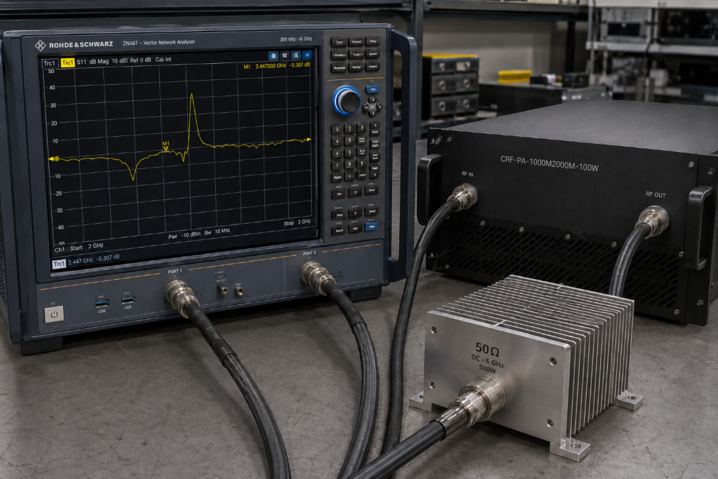
Engineers utilize specific instruments for identifying these mechanical faults. A Vector Network Analyzer connected to a suspect cable run shows distinct patterns. This is where things get interesting. The S11 return loss trace will bounce violently when a technician taps the chassis. A stable trace indicates solid connections. A bouncing trace confirms mechanical failure. Time Domain Reflectometry pinpoints the exact distance to the fault. TDR displays an impedance spike exactly at the rack interface. Spectrum analyzers reveal different symptoms. A loose connector acting as a diode generates intermodulation distortion. The noise floor rises significantly during engine acceleration. Carrier signals exhibit strange sidebands. These sidebands correlate exactly with engine RPM frequencies. Power meters show rapid fluctuations. A steady 200W carrier drops to 50W, then recovers. These symptoms never appear during static lab testing. They only manifest under active mechanical load. Identifying these signatures requires real-time monitoring while the vessel operates at sea.
Diagnostic Instrument Response | Fault Condition | Observed Signature
Vector Network Analyzer (S11) | Micro-crack in solder joint | Trace instability during physical shock
Time Domain Reflectometer | Loose connector interface | Abrupt positive impedance spike at interface distance
Spectrum Analyzer | Oxidized loose connection | Elevated noise floor and mechanical sidebands
Directional Power Meter | Intermittent open circuit | Rapid forward power fluctuation and reverse power spikes
4. How Do You Isolate Intermittent VSWR Spikes on Deck?
Isolating intermittent faults demands a methodical process. Random component swapping wastes valuable maintenance hours. Begin with the primary transmission line. Disconnect the main antenna feed. Terminate the amplifier output with a precision 50-ohm dummy load. You might be wondering, why use a dummy load? This eliminates the entire external antenna system from the equation. Run the system at full power. If VSWR spikes persist, the fault lies within the amplifier or the immediate jumper cables. Next, apply physical stress testing. Gently manipulate the input and output cables. Monitor the power meter. A sudden drop confirms a bad cable termination. If cables pass, focus on the amplifier chassis. Tap the unit lightly with a non-metallic tool. Watch for SWR alarms. The CRF-PA-1000M2000M-200W features built-in protection for over-voltage, over-temperature, over-drive and VSWR. When a micro-crack opens under vibration, internal logic detects the sudden impedance shift. It immediately reduces drive current. Monitoring the RS485 or LAN control interface provides exact timestamps for these protection events. Matching these timestamps with engine RPM logs isolates the resonant frequency causing the failure.
5. Why Do Commercial Off-The-Shelf Amplifiers Fail Here?
Standard commercial amplifiers utilize cost-effective construction methods. They rely on commercial-grade FR4 circuit boards. Large components lack mechanical staking or silicone adhesive support. Their chassis panels use thin aluminum prone to flexing. Let me explain, when commercial gear meets a marine engine room, destruction happens quickly. Thin chassis flex under acoustic pressure. Circuit boards bend. Surface-mount ceramic capacitors crack under the bending stress. Commercial heat sinks use standard fins that resonate audibly. This resonance literally tears power transistors off their copper heat spreaders. Connectors lack locking washers or safety wire holes. Cooling fans use cheap sleeve bearings. These bearings fail rapidly under continuous gyroscopic force from ship movement. A commercial unit might claim a 200W output, but it cannot sustain it while vibrating at 40 Hz. The internal mismatch creates heat. The failing fan cannot remove the heat. Thermal runaway destroys the active devices. Commercial designs simply lack the ruggedized physical architecture required for maritime survival.
Commercial vs Ruggedized Architecture | Component Area | Commercial Design | Ruggedized Requirement
PCB Material | Standard FR4 | High-frequency low-loss laminate with structural rigidity
Component Mounting | Standard Solder | Mechanical staking and conformal coating
Connector Hardware | Standard Threaded | Lock washers, safety wire compatible, specific torque ratings
Chassis Construction | Thin bent aluminum | Heavy-gauge milled aluminum block or reinforced extrusions
6. What Makes The CRF-PA-1000M2000M-200W Different?
The CRF-PA-1000M2000M-200W represents a purpose-built solution for demanding environments. This Wideband RF Power Amplifier covers a frequency range of 1,000 – 2,000 MHz. It delivers a reliable rated output power of 200 W. The design philosophy centers on mechanical stability and electrical resilience. Ready for the good part? The package size is 19 inches, 4U, weighing 20kg. That 20kg mass provides significant mechanical damping against low-frequency vibration. Heavy mass resists acceleration. The RF Connectors are N-Female for both Input and Output. These connectors anchor directly to thick chassis bulkheads, preventing torque transfer to internal boards. It operates within a 50-ohm system. Gain sits at a typical 53 dB. Gain Flatness remains tight between -3 and 3 dB. Adjustable Gain offers up to 20 dB of control. This allows operators to fine-tune drive levels directly compensating for external cable losses. Power consumption maxes out at 1000 W. The unit requires an AC 220V±10%, 50/60Hz power supply.
7. How Does Advanced GaN Technology Handle Engine Room Stress?
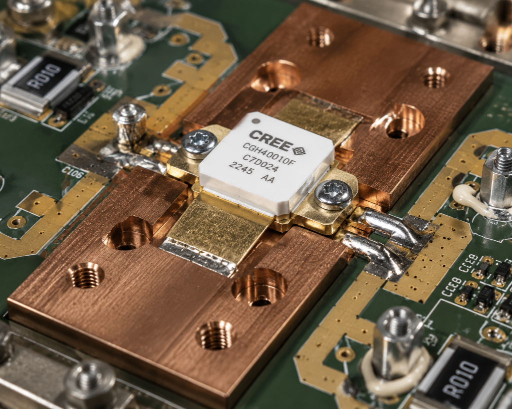
The core amplifier design is based on advanced GaN technology. Gallium Nitride devices offer superior power density compared to older LDMOS silicon. This means smaller active devices handle more power. Smaller devices possess less mass. Less mass means lower susceptibility to vibration-induced shear forces. Here is the kicker, GaN operates efficiently at higher temperatures. Engine rooms run hot. Operating Temperature ranges from 0 to 50 °C. The system utilizes Air cooling. High-efficiency GaN reduces the total thermal load the cooling system must manage. Harmonics are kept below -10 dBc. Spurious emissions remain exceptionally low at -60 dBc. This clean spectral output prevents interference with other sensitive shipboard receivers. Input Power operates at a typical 0 dBm. The robust GaN architecture handles momentary load mismatches better than legacy technologies. When a loose connector causes a sudden reflection, the GaN transistor survives the voltage spike long enough for digital protection circuits to engage.
CRF-PA-1000M2000M-200W Specifications | Parameter | Value | Unit
Frequency Range | 1,000 – 2,000 | MHz
Rated Output Power | 200 | W
Gain (Typical) | 53 | dB
Input VSWR (Typical)| 1.5:1 | Ratio
Spurious (Max) | -60 | dBc
8. How Can Built-In Protection Circuitry Prevent Catastrophic Failure?
Mechanical failures eventually happen regardless of preparation. Defense relies on rapid detection and mitigation. The CRF-PA-1000M2000M-200W includes built-in protection: over-voltage, over-temperature, over-drive and VSWR. You must realize, these systems react in microseconds. If a vibration shears an antenna feed line, VSWR shoots to infinity. The protection circuit detects the severe mismatch instantly. It shuts down the RF drive before the reflected power melts the GaN devices. Over-temperature sensors monitor the heat sink. If engine room ambient temps exceed safe limits, or if a fan intake blocks, the system throttles power. Over-drive protection stops excessive input signals from destroying the front-end stages. The system provides a Control Interface via RS485 / LAN. Operators monitor these protection flags remotely. A persistent VSWR flag isolates the problem to the physical RF path. Customization options include Optional forward/reverse power monitoring, input power detection and GPIB control interface. These options provide even deeper diagnostic visibility for systems integrators.
9. What Are The Integration Requirements For 4U Rackmount Systems?
Proper installation dictates long-term survival. The model CRF-PA-1000M2000M-200W requires specific mounting protocols. Pay close attention, bolting a 20kg 4U chassis directly into a rigid rack near an engine guarantees failure. Integrators must use wire-rope shock mounts or elastomeric isolators. These mounts decouple the rack from hull vibrations. A complete outline drawing provides clear integration reference. The dimensions show a width of 483mm and a depth of 586mm. Rear support rails are mandatory. Securing only the front panel bends the mounting ears under 20kg of dynamic load. RF cables require strain relief within six inches of the N-Female connectors. This prevents cable whip from unthreading the interface. Applications span Test & measurement, communication, interference, and aviation control. Compliance includes RoHS Compliant, CE / FCC, ISO 9001, and GJB 9001C. Quality frameworks ensure consistency. Test data and pattern files can be supplied for project review where applicable.
Installation Requirements | Sub-system | Requirement Parameter
Mechanical Mounting | Shock-isolated rack | Elastomeric or wire-rope isolators rated for 20kg+
Rear Support | Mandatory rail support | Prevents front-panel shear under vibration
RF Cable Strain Relief | Within 6 inches of port | Prevents torque transfer to N-Female connector
Clearance | Front/Rear airflow path | Necessary for proper Air cooling operation
10. How Should You Execute Preventative Maintenance in High-Vibration Zones?
Preventative maintenance stops emergencies. Establish a rigid inspection schedule based on engine operating hours. This alters everything regarding uptime. Every 500 hours, physically inspect all RF connections. Use a calibrated torque wrench on every N-Female connector. Re-torque them to exact specifications. Visual inspection fails to detect a connector loosened by five degrees. Check the input VSWR specification. It should read near the typical 1.5:1. Connect a network analyzer and perform the tap test on the chassis. Any trace instability requires immediate amplifier removal and internal inspection. Log all RS485 / LAN control interface alarms. Frequent, brief VSWR alarms indicate a failing joint before complete separation occurs. Clean air intake grilles regularly. Engine rooms contain oily vapor. This vapor clogs Air cooling mechanisms fast. Maintaining clean airflow keeps the GaN devices well below the 50 °C maximum Operating Temperature.
Mechanical vibration dictates electronic reliability within heavy industrial naval applications. Utilizing specialized hardware containing advanced protection systems prevents physical degradation from causing total system failure. Integrators facing these harsh mechanical realities should evaluate dedicated RF modules engineered specifically for continuous kinetic stress.
Q1: What is the frequency range of the CRF-PA-1000M2000M-200W?
The CRF-PA-1000M2000M-200W operates across a frequency range of 1,000 – 2,000 MHz.
Q2: How does the built-in protection work?
The unit features built-in protection for over-voltage, over-temperature, over-drive and VSWR, which shuts down or throttles the system to prevent damage.
Q3: What type of RF connectors are used on this amplifier?
The RF Connectors In/Out are Input: N-Female and Output: N-Female.
Q4: What are the control interface options available?
The amplifier supports Control Interface via RS485 / LAN.
Q5: What cooling method does the system use?
The system relies on an Air cooling method to manage heat dissipation.
Authorized RF engineering and compliance review
For regulated RF systems, this page should be used as an engineering and compliance review path, not as a public deployment checklist. CorelixRF starts with authorization status, operating region, frequency plan, output limit, antenna interface, safety controls, thermal limits and acceptance documents.
- RFQ checklist – send the data buyers usually forget, including band, power, duty cycle, interface and test standard
- delivery documentation – check what documents can support incoming inspection, FAT review and long-term maintenance
- quality and certification review – review the quality and compliance evidence before the project moves into procurement
- RF front-end platform – compare the RF chain as a system instead of selecting one isolated module
- RF configurator – turn frequency, power, thermal and interface requirements into a first configuration brief
- case studies – review similar engineering paths before sending an RFQ
- engineering contact – send the application notes, block diagram or target specification to engineering sales
This keeps the discussion inside lawful, authorized RF programs while still giving procurement teams a clear way to request amplifier, antenna, SDR source, documentation and factory review.
From Signal Anomaly to RFQ Path
After isolating vibration, mismatch and cabling causes, compare the system against CorelixRF RF power amplifier options, RF front-end platforms, and RF antenna integration requirements.
Submit operating band, signal symptoms, VSWR limits and acceptance documents for a factory review.