
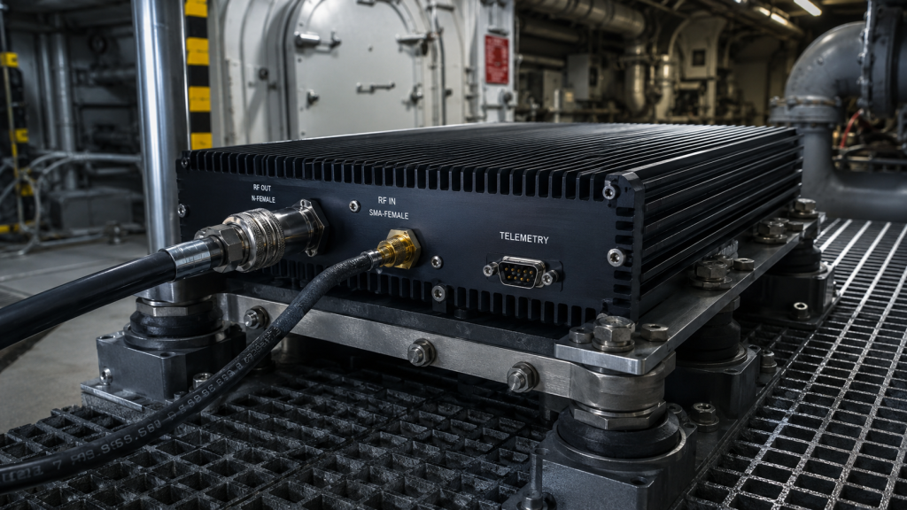
Engineers mounting wideband RF power amplifiers directly inside ship hulls face continuous mechanical violence. Massive diesel turbines generate continuous cyclical shockwaves, silently fatiguing standard electronic components over months of maritime deployment. Suddenly, radar screens go blank during operations because unseen internal solder joints sheared apart. Such failures trigger cascading VSWR faults, destroying output transistors instantly. Here is the deal CorelixRF engineers high-power enclosures using advanced GaN technology and ruggedized architecture. We solve mechanical fatigue from its root physics.
How Does Low-Frequency Vibration Propagate Within Naval Engine Rooms?
● Diesel Engine Vibration Profiles
● Harmonic Resonance In Metal Structures
● Shockwave Impact On RF Equipment
Shipborne environments produce distinct mechanical stress profiles vastly different from aerospace applications. Massive rotary machinery generates relentless acoustic energy propagating through metal decking directly into mounted equipment racks. These cyclical waves range between low frequencies, matching natural resonant frequencies found within poorly designed chassis structures. Let that sink in for a moment. When ambient frequencies match chassis resonance, physical displacement multiplies exponentially. Standard thin-walled aluminum boxes violently flex under such conditions, transferring amplified kinetic energy straight onto internal printed circuit boards. Engineers observing spectrum analyzer screens often notice sudden noise floor spikes correlating directly with turbine RPM surges. This erratic baseline shifting indicates active mechanical interference modulating sensitive microwave paths. Effectively combating these forces requires rigid rack-mount chassis enclosures rather than small discrete modules. A substantial physical mass, properly isolated using heavy-duty dampening mounts, disrupts kinetic wave transmission before destructive energy reaches delicate internal active components.
Vibration Propagation Modes | Physical Impact
Direct Structural Conduction | Substrate flexing and track delamination
Acoustic Wave Coupling | Component micro-phonics and cavity resonance
Harmonic Amplification | Exponential stress on mounting points
Thermal-Kinetic Compounding | Accelerated material fatigue at high temps
Why Do Standard RF Connectors Loosen Under Continuous Mechanical Stress?
● Thread Wear Mechanics
● Torque Degradation Over Time
● Output VSWR Spikes Microwave interfaces represent primary failure points during sustained mechanical shaking.
Standard threaded couplings rely strictly on metal-to-metal friction maintained by initial tightening torque. Relentless kinetic cycling gradually overcomes this static friction, backing threads out microscopic amounts daily. Consider this reality. An N-Female output connector carrying two hundred watts of continuous wave power cannot tolerate any physical gap. Microscopic separation introduces severe impedance mismatches, instantly spiking reverse power levels back toward final stage transistors. Unprotected circuitry burns out milliseconds later. Input connectors utilizing SMA-Female designs suffer similarly when subjected to rigid coaxial cable pulling forces. Technicians troubleshooting dropped links frequently discover completely loose RF junctions requiring only finger pressure for removal. Proper engineering practice demands semi-rigid cable assemblies featuring specific bend radii acting as mechanical strain reliefs. Furthermore, applying safety wire or specified thread-locking compounds during factory assembly prevents rotational loosening regardless of ambient kinetic severity.
RF Interface | Specification | Vibration Risk Profile
Input Interface | SMA-Female | High risk without strain relief Output Interface | N-Female | Severe arcing risk if loosened Control Link | RS485 | Pin fretting corrosion Power Terminal | 4-Pin Aviation | Retaining ring back-out
What Causes Micro-Solder Cracking Inside High-Power Amplifiers?
● Coefficient Of Thermal Expansion Mismatch
● Intermetallic Compound Fatigue
● Cold Joint Propagation Internal component detachment remains a highly insidious maritime failure mode.
Printed circuit boards manufactured from PTFE laminates exhibit vastly different thermal expansion coefficients compared to ceramic surface-mount capacitors or GaN transistor flanges. Operating hardware cycles between -20 Celsius and 60 Celsius routinely, causing dissimilar materials to expand at unequal rates. This thermal action creates constant shear stress across lead-free solder junctions. This brings us to a critical realization. Injecting continuous physical shaking into an already thermally strained junction accelerates intermetallic crystalline fracturing dramatically. Micro-cracks initiate invisibly beneath component pads, propagating slowly through subsequent thermal and kinetic cycles until electrical continuity vanishes entirely. Such broken traces near final stage amplification blocks cause immediate uncontrolled oscillation or total signal loss. CorelixRF combats these failures utilizing specialized elastic solder alloys combined with heavy conformal coating applications, permanently bonding components against dual-mode environmental destruction.
How Does Rack-Mount Chassis Design Improve System Reliability?
● Large Mass Dampening
● Rack-Mount Enclosure Necessity
● Internal Board Segregation Deploying high-power S-band arrays requires substantial structural foundations.
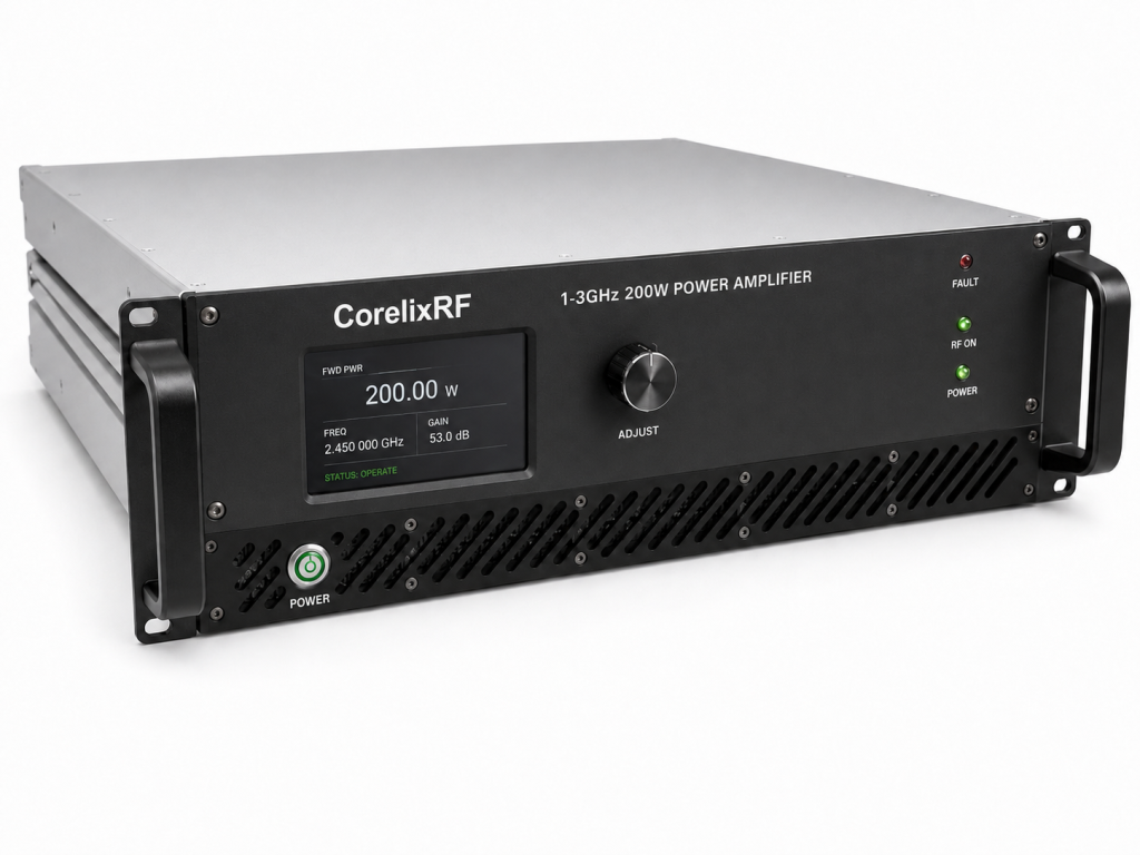
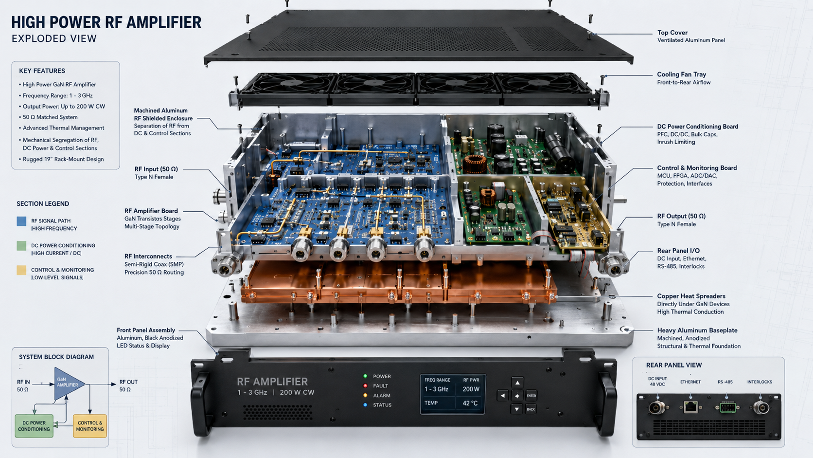
Lightweight, miniaturized modules completely fail when subjected to naval engine harmonics. Superior system-level architecture demands a robust rack-mount form factor measuring exactly 350x200x50 mm. What does this mean for you? This specific dimensional geometry allows for thick-walled housing construction, effectively shifting the structural resonant frequency far above any engine-produced harmonic. Mass acts as an inherent low-pass filter against kinetic energy. Inside these heavy enclosures, designers must segregate RF routing from DC conditioning boards using machined aluminum partitions. These metal walls serve dual purposes: providing exceptional electromagnetic shielding while acting as internal stiffening ribs preventing board flex. Every internal coaxial connection utilizes specifically routed semi-rigid lines absorbing any residual shock bypassing external dampening systems. True engineering truth dictates prioritizing rigid mechanical volume over space-saving gimmicks when reliability dictates mission success.
Physical Parameter | CorelixRF Specification
Dimensions | 350*200*50mm Input Connector | SMA-Female Output Connector | N-Female Cooling Strategy | External heatsink air cooling
How Do Thermal Dissipation And Mechanical Strain Intersect?
● Thermal Cycling Mechanics
● GaN Transistor Mounting
● External Heatsink Structural Integrity Heat extraction poses massive challenges when equipment undergoes constant physical shaking.
Generating two hundred watts of RF energy produces immense localized thermal concentrations requiring rapid dispersion. Flange-mounted GaN components must maintain perfect planar contact with baseplates. However, kinetic waves constantly attempt to warp or bend these mating surfaces, threatening thermal conductivity. Here lies the real problem. A microscopic air gap introduced by chassis flexing acts as a total thermal barrier, skyrocketing transistor die temperatures past destruction limits instantly. Our methodology relies on precision-machined copper spreaders bolted through heavy steel inserts, guaranteeing absolute flatness regardless of external twisting forces. The CRF-PA-1000M3000M-200W utilizes an external heatsink air cooling approach, structurally integrating massive cooling fins directly into the primary load-bearing chassis. This unified metal block construction handles storage conditions reaching 85 Celsius without degrading structural integrity or solder joint strength.
Temperature Condition | Specification Limit
Operating Minimum | -20 C Operating Maximum | 60 C Storage Minimum | -40 C Storage Maximum | 85 C
What Intelligent Protection Mechanisms Prevent Catastrophic VSWR Failures?
● Built-In Alarm Logic
● Over-Drive And Current Thresholds
● Antenna Feedback Loops Hardware survival depends heavily on autonomous internal defense systems reacting faster than human operators.
When an external antenna gets damaged by seawater spray or physical impact, returning energy threatens the entire RF chain. Continuous vibration increases likelihood of sudden open circuits at output nodes. Look at the facts here. The hardware features comprehensive built-in protection against over-voltage, over-current, and severe VSWR conditions. An instantaneous hardware interrupt cuts bias voltage upon detecting reverse power spikes exceeding safe thresholds. Simultaneously, thermal monitors track baseplate heat, triggering a hardware alarm threshold at exactly 70±5 Celsius. This multi-layered defense matrix also includes open/short circuit protection and over-drive prevention, ensuring that sudden load impedance changes caused by mechanically severed cables do not result in silicon vaporization.
How Does CorelixRF Hardware Solve Maritime Environmental Challenges?
● Broad Spectrum Coverage
● Power Flatness Parameters
● Uncompromising Electrical Standards Operating wideband signals amidst extreme mechanical noise demands extraordinary electrical foundations.
The CRF-PA-1000M3000M-200W delivers continuous operation across a demanding 1,000-3,000 MHz spectrum. Generating exactly 200 W rated output requires maintaining pristine input matching. The unit guarantees an input VSWR holding steady at 1.5:1 , accepting a 0 dBm input drive level. Here is another fact. Signal purity remains paramount even when the surrounding structure violently shakes. Engineers measure harmonics consistently suppressed at -10 dBc , while spurious emissions stay buried down at -60 dBc. Achieving a massive 53 dB gain with a tight gain flatness of -3 to 3 dB under load confirms superior matching network stability. The hardware delivers consistent metrics whether bolted to a static test bench or bolted inside a churning destroyer engine room.
RF Performance Metric | Specified Value
Operating Frequency | 1,000-3,000 MHz Gain Specification | 53 dB Input Power Level | 0 dBm Harmonic Suppression | -10 dBc
What Control Interfaces Ensure Reliable Telemetry Reporting?
● RS485 Communication Protocol
● DB9 Pin Monitor Definitions
● High-Current DC Supply Management Telemetry data extraction provides operators crucial insight regarding hardware health during deployments.
Fragile consumer-grade data cables shake loose instantly under maritime conditions. Industrial communication relies entirely on robust physical links capable of locking down tight. This is where things get serious. The DB9 interface provides ruggedized connectivity for continuous monitoring. Pin 1 and Pin 2 handle the RS485 serial communication bus, offering noise-immune differential signaling. Operators monitor exact forward power, reverse power, and temperature parameters using specific detection voltage outputs on Pins 6, 7, and 8 respectively. Pin 5 delivers real-time current monitor voltage. Driving this heavy telemetry load requires massive DC inputs, specifically +24V to 32V DC, nominally running at +28V. The power supply pulls a hefty 25A typical, peaking at 30A under maximum drive.
How Do We Verify RF Performance Under Constant Strain?
● System Impedance Standards
● Specialized Pattern Verification
● Factory Compliance Testing Trusting hardware in maritime applications requires rigorous, documented physical proof prior to shipment.
Subjecting finished assemblies to multi-axis shaker tables simulates decades of engine room abuse within days. CorelixRF performs all standard evaluations utilizing strict 50 Ω test conditions. You must understand this point. We never estimate survivability; every unit undergoes severe scrutiny matching exact deployment conditions. During project review phases, test data and pattern files can be supplied directly to system integrators. This transparency allows radar and communication architects complete visibility into how the RF chain behaves when pushed toward mechanical limits. The hardware architecture complies with RoHS standards , CE / FCC directives , ISO 9001 , and GJB 9001C military quality frameworks, verifying absolute engineering rigor from blueprint creation through final factory dispatch.
What Are The Next Steps For Reliable System Integration?
● Integrating Custom Interfaces
● GPIB And LAN Control Options
● Mechanical Drawing Implementation Deploying high-power amplifiers demands seamless integration with existing upstream shipboard control systems.
Engineers require precise mechanical models for laying out racks and calculating exact mounting bolt locations. CorelixRF supplies a detailed mechanical drawing specifically intended for installation reference. Here is the final piece. Final dimensions remain subject to actual production unit tolerances, but the baseline chassis offers extreme rigidity. For advanced automated command centers, optional forward/reverse power monitoring, GPIB control interfaces, and LAN remote control options are available. These features integrate directly into master vessel management software, allowing complete hands-off RF operations. Engineers configuring aviation control, test and measurement, or interference arrays secure unmatched physical reliability by standardizing around this specific architecture.
Eliminating engine room hardware failures demands addressing root physical causes like harmonic resonance and thermal shear stress. Implementing the CRF-PA-1000M3000M-200W guarantees uninterrupted 200W signal delivery through advanced GaN implementation and heavy rack-mount isolation. System integrators requiring absolute stability should request full test patterns immediately. Contact CorelixRF engineering to evaluate integration schematics today.
Q1: What is the specific frequency range and output power of this amplifier?
The hardware operates continuously across a 1,000-3,000 MHz spectrum, delivering a rated output power of 200 W under standard 50-ohm test conditions.
Q2: How does the built-in protection system function?
It guards against catastrophic failure by monitoring for over-voltage, over-current, open/short circuits, over-temperature (70±5℃ alarm threshold), over-drive, and VSWR mismatches.
Q3: What type of control and telemetry interfaces are provided?
The system utilizes an RS485 control interface accessed via a standard DB9 connector, which outputs dedicated analog voltages for temperature, current, forward power, and reverse power monitoring.
Q4: What are the physical dimensions and cooling requirements?
The heavy-duty rack-mount chassis measures 350x200x50 mm and relies strictly on external heatsink air cooling to dissipate internal heat safely.
Q5: What quality and compliance frameworks support this product?
The hardware design and manufacturing processes fully comply with RoHS, CE / FCC, ISO 9001, and GJB 9001C strict quality standards.
Authorized RF engineering and compliance review
For regulated RF systems, this page should be used as an engineering and compliance review path, not as a public deployment checklist. CorelixRF starts with authorization status, operating region, frequency plan, output limit, antenna interface, safety controls, thermal limits and acceptance documents.
- RFQ checklist – send the data buyers usually forget, including band, power, duty cycle, interface and test standard
- delivery documentation – check what documents can support incoming inspection, FAT review and long-term maintenance
- quality and certification review – review the quality and compliance evidence before the project moves into procurement
- RF front-end platform – compare the RF chain as a system instead of selecting one isolated module
- RF configurator – turn frequency, power, thermal and interface requirements into a first configuration brief
- case studies – review similar engineering paths before sending an RFQ
- engineering contact – send the application notes, block diagram or target specification to engineering sales
This keeps the discussion inside lawful, authorized RF programs while still giving procurement teams a clear way to request amplifier, antenna, SDR source, documentation and factory review.
Naval RF Amplifier Engineering Path
When vibration, high VSWR or sealed installation raises risk, move from the selection guide to a suitable RF power amplifier, a matching RF front-end platform, or a custom amplifier with FAT evidence.