
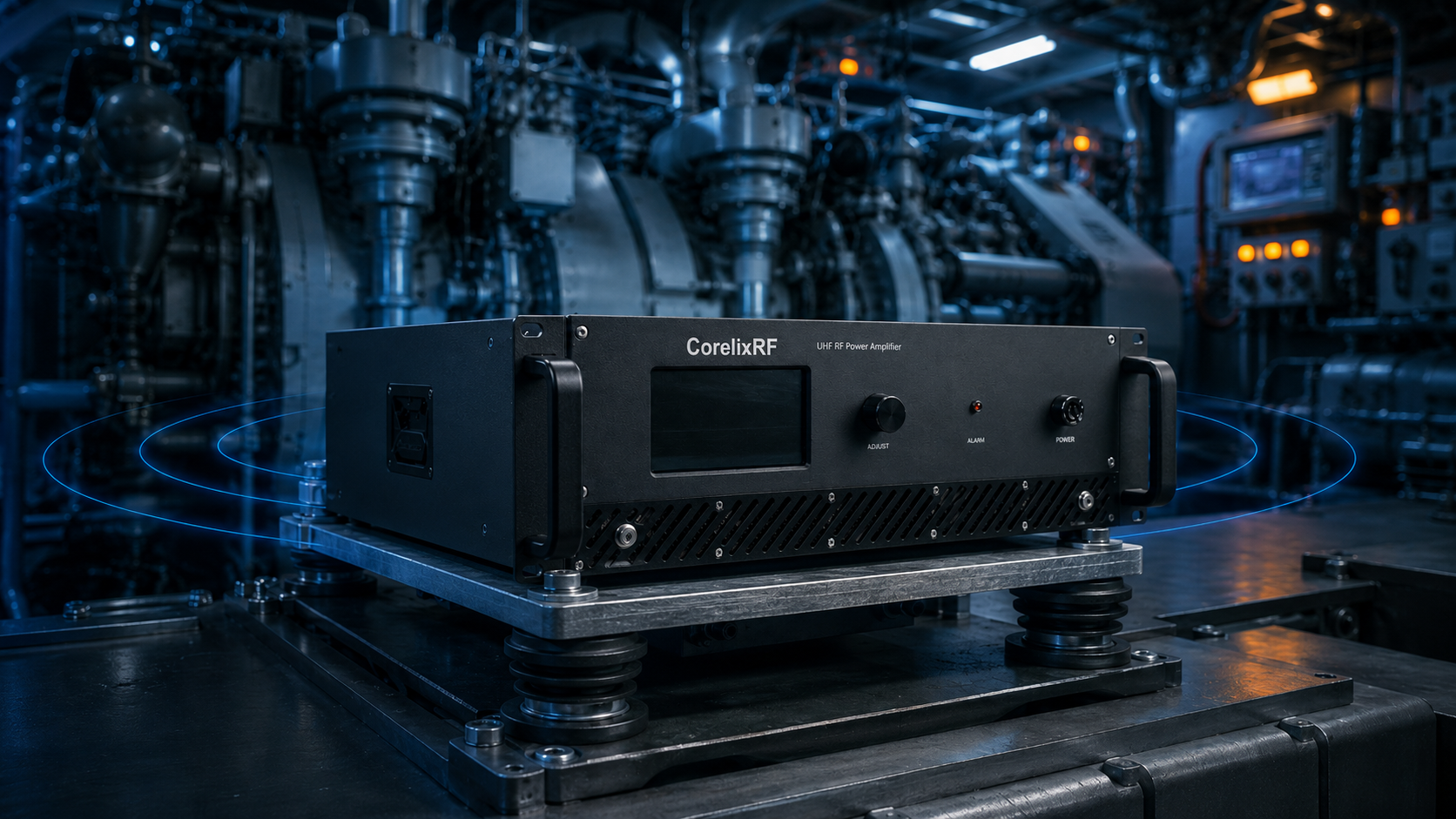
Naval engine rooms present severe mechanical challenges for radio frequency systems. Massive diesel propulsion systems generate continuous low-frequency vibrations. These relentless movements compromise standard amplifier front-ends constantly. Solder joints crack under continuous sheer stress. Coaxial connectors loosen over repeated engine cycles. RF performance degrades rapidly without warning. CorelixRF presents a distinct hardware selection logic for this environment. We recommend deploying our CRF-PA-800M2500M-100W unit. This specific model mitigates mechanical fatigue through calculated structural designs. I will detail specific physical mechanisms causing these common component failures. My analysis relies on twenty years of field troubleshooting experience. We solve these problems using targeted engineering countermeasures.
Naval Engine Room RF Front-End Degradation
Identifying Systemic Field Failures
Here is the deal. Operators aboard maritime vessels dread sudden voltage standing wave ratio alarms appearing randomly. These warnings often stem directly from physical hardware degradation below decks. A ship’s diesel power plant creates harsh continuous vibration profiles. I investigated a one gigahertz communication array losing three decibels of output power recently. An input SMA connection had backed out by just a fraction of a millimeter. Another case involved a radar jamming unit entering auto-shutdown unexpectedly. We traced that failure back toward cracked circuit board solder joints underneath a high-power transistor. A third instance showed a spectrum analyzer displaying an abnormally high noise floor. The chassis ground path had degraded from constant shaking. These symptoms point toward inadequate mechanical foresight during initial component specification phases. Standard commercial off-the-shelf equipment cannot survive long-term exposure inside such violent environments. You must understand how kinetic energy dismantles electronics module by module.
Reference Data
| Failure Mode | Root Cause | System Impact |
| VSWR Alarm | Connector Loosening | Auto-shutdown triggered |
| Power Drop | Micro-Solder Crack | 3dB output loss |
| Noise Floor Rise | Ground Loop Shift | Signal masking |
The Engineering Truth: Low-Frequency Vibration Mechanics
Analyzing Resonance and Fatigue
You might be wondering. Why do standard ruggedized amplifiers fail repeatedly near heavy marine propulsion machinery? The answer lies within structural resonance frequencies. Large marine diesels typically shake heavily between ten and fifty hertz. Printed circuit boards possess specific natural resonant frequencies depending upon their mounting configurations. Displacement amplitudes multiply exponentially if environmental vibration matches a board’s natural resonance. Micro-solder joint fatigue accelerates rapidly under combined thermal and mechanical loads. Lead-free solder becomes brittle and shears apart eventually. Furthermore, threaded coaxial interfaces lack sufficient prevailing torque by default. Constant shaking slowly unwinds standard coupling nuts over several weeks. A microscopic air gap forms between center pins. This gap introduces massive impedance mismatches instantly. Reflected energy then surges back toward delicate driver stages. A 100 W amplifier driving a 1.5:1 VSWR load encounters significant returning power. Standing waves create localized high-voltage nodes stressing dielectric materials continually. Field engineers often find charred RF traces resulting directly from a loose connector backing out just a half turn. We mathematically model these displacement vectors during our initial product design phases. Understanding modal analysis allows us predicting exactly where a printed circuit board will flex worst.
Reference Data
| Parameter | Value | Unit |
| Engine Vibration | 10 – 50 | Hertz |
| Solder Stress | Shear | Type |
| Impedance Mismatch | High | Impact |
Hardware Selection: Avoiding Common Naval Engine Room BOM Traps
Prioritizing Structural Integrity
What is the real story? Engineers must shift focus toward structural integrity during initial bill of materials generation. Specifying a radio frequency amplifier requires evaluating mechanical damping properties alongside electrical specifications. A lightweight aluminum housing might seem appealing for weight reduction purposes. However, inadequate mass allows low-frequency waves from hull structures direct access toward internal components. Link budgets deteriorate quickly when mating forces weaken at interface boundaries. Insertion loss spikes unexpectedly due to poor surface contact. We must select connectors featuring anti-vibration mechanisms or specify safety wire holes. Internal matching networks need heavy potting compounds protecting sensitive surface mount inductors. Upstream system design dictates final reliability far more heavily than reactive maintenance schedules. We prioritize heavy-duty rack-mounted chassis designs for dissipating both heat and kinetic energy simultaneously. Many system integrators ignore the reality of galvanic corrosion combined with constant motion. A naval engine room atmosphere contains high levels of salt vapor and oily mist. When a connector loosens slightly, this corrosive mixture penetrates the interface immediately. Copper oxidation spikes contact resistance exponentially. Your link budget evaporates within days under these specific conditions. Choosing hardware with integrated environmental sealing and high-mass vibration damping becomes a mandatory engineering requirement. We refuse compromising on these foundational structural elements.
Section 3 Reference Data
| Component | Selection Criterion | Reason |
| Chassis | High Mass / 3U | Vibration damping |
| Connectors | Thread-locking | Prevent back-out |
| Inductors | Potting compound | Stabilize mass |
The CorelixRF Solution: Deploying the CRF-PA-800M2500M-100W
Leveraging Mass and Advanced Transistors
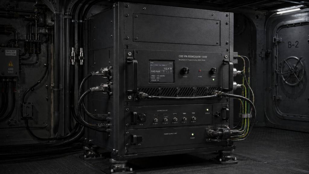
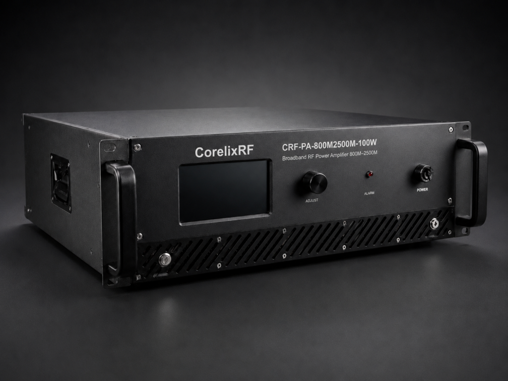
Ready for the good part? We engineered specific physical characteristics into our recommended power amplifier combating marine environment challenges. CorelixRF CRF-PA-800M2500M-100W operates across a frequency range covering 800 – 2,500 MHz. This unit delivers a rated output power of 100 W consistently. We built this device utilizing advanced GaN technology. Package size measures 19 inches across and occupies a 3U rack space. Heavy 16kg physical mass acts as an excellent mechanical low-pass filter. We selected an N-Female connector for output ports specifically because its larger thread pitch resists vibration better than smaller alternatives. Input circuitry utilizes a secure SMA-Female interface. Furthermore, we included built-in protection circuits handling over-voltage, over-temperature, over-drive, and VSWR anomalies. These safeguards act instantly if a cable gets damaged externally. GaN technology provides superior power density and ruggedness compared with legacy LDMOS devices. High electron mobility transistors withstand higher voltage standing wave ratios without suffering catastrophic breakdown. Our engineering team designed wideband matching networks specifically avoiding sharp resonant peaks. Flat gain characteristics spanning the entire 800 – 2,500 MHz band deliver consistent performance regardless of operational frequency. You receive a reliable platform capable of surviving extreme mechanical and electrical abuse simultaneously.
Reference Data
| Specification | Value | Source |
| Frequency Range | 800 – 2,500 MHz | |
| Rated Output Power | 100 W | |
| Input VSWR | 1.5:1 max |
System Integration: Thermal Dissipation and Interface Management
Controlling Heat and Electromagnetic Interference
This is where it gets interesting. Integrating high-power RF gear near ship powerplants demands rigorous attention regarding environmental variables. CorelixRF CRF-PA-800M2500M-100W consumes 500 W of electrical power during operation. We implemented forced air cooling methods managing thermal loads effectively. Equipment functions reliably within an operating temperature window spanning 0 to 50 °C. Naval engine rooms generate intense electromagnetic interference from large alternator fields. We chose an RS485 control interface specifically for navigating these electrically noisy surroundings. Differential signaling protocols reject common-mode noise far better than standard serial connections. We also supply mechanical drawings providing clear integration references for final rack assembly. Proper integration practices prevent premature component failure before a vessel even leaves its drydock facility. Ground loops present another severe challenge near heavy rotating machinery. A ship’s alternator generates massive magnetic fields inducing stray currents across poorly grounded equipment racks. The RS485 standard utilizes twisted pair wiring canceling out these induced voltages effectively. Your control signals remain pristine even during full engine throttle maneuvers. We mandate strict adherence regarding grounding protocols and cable strain relief installations. A heavy-duty power amplifier requires equally robust cabling infrastructure supporting its continuous operation.
Reference Data
| Parameter | Value | Specification |
| Power Consumption | 500 W | |
| Operating Temperature | 0 to 50 °C | |
| Control Interface | RS485 |
Conclusion: Securing the RF Front-End
Final Engineering Recommendations
Here is the kicker. Naval engine room environments destroy poorly specified radio frequency equipment relentlessly. Engineers must address low-frequency vibration and thermal cycling immediately during early hardware selection phases. Our CorelixRF CRF-PA-800M2500M-100W mitigates these physical threats through intelligent mechanical design and robust built-in protections. We understand the frustration caused by phantom alarms interrupting critical vessel operations. You need hardware capable of surviving continuous mechanical punishment without faltering. Stop replacing burned-out modules continuously due to ignored structural realities. Contact our technical applications team today for a complete datasheet review regarding your next demanding shipboard integration project.
FAQ Section
Q1: What frequency range does the CRF-PA-800M2500M-100W cover during normal operation?
Our recommended amplifier operates efficiently across a broad spectrum spanning 800 – 2,500 MHz. This wide bandwidth supports multiple communication protocols and radar jamming frequencies simultaneously. Engineers can consolidate several narrow-band modules into one robust chassis. Consolidating hardware reduces overall system complexity significantly. Fewer physical connections mean fewer potential failure points under heavy vibration. We designed this flexibility specifically for constrained naval environments demanding high reliability. You gain significant operational headroom by selecting a wideband solution capable of adapting toward future electronic warfare requirements.
Q2: How does the system protect against sudden impedance mismatches?
We integrated comprehensive safeguard circuits directly into the amplifier architecture. The device features built-in protection against over-voltage, over-temperature, over-drive, and severe VSWR conditions. A disconnected cable or a damaged antenna triggers these defense mechanisms instantly. The unit shuts down power delivery before reflected energy destroys sensitive internal GaN transistors. Operators receive immediate diagnostic feedback via the RS485 control interface. This rapid response prevents catastrophic hardware loss during active maritime deployments. You avoid costly repairs and maintain mission readiness even when external transmission lines fail unexpectedly.
Q3: Why did CorelixRF select an N-Female output connector?
We specified an N-Female interface for the RF output port primarily due to its superior mechanical characteristics. Naval engine rooms generate continuous shaking capable of loosening smaller coaxial threads. N-type connectors feature a larger thread pitch and greater mating surface area. This design provides higher prevailing torque holding the connection secure over long durations. A 100 W continuous wave signal requires absolute physical stability preventing localized heating or arcing. You eliminate intermittent power drops caused by microscopic air gaps forming between center pins.
Q4: What thermal management strategy cools this amplifier?
The CRF-PA-800M2500M-100W utilizes a highly efficient forced air cooling method. High-power radio frequency generation produces significant waste heat requiring immediate extraction. Our design pulls ambient air across specially engineered internal heat sinks. The system handles up to 500 W of total power consumption safely. Rated operating temperatures span continuously from 0 to 50 °C without performance degradation. Maintaining a stable internal climate prevents thermal cycling from fatiguing micro-solder joints prematurely. Your installation remains stable even deep inside poorly ventilated ship compartments.
Q5: How does chassis weight influence system reliability?
A heavy physical enclosure provides massive benefits regarding structural vibration damping. The 19-inch 3U package weighs a substantial 16kg fully assembled. This significant mass shifts the overall resonant frequency away from typical diesel engine operational bands. Low-frequency kinetic energy dissipates harmlessly through the thick metal chassis before reaching delicate internal printed circuit boards. We utilized this specific form factor acting essentially as a mechanical low-pass filter. Your sensitive matching networks remain isolated from destructive shaking forces entirely. This upstream hardware selection logic prevents microscopic solder cracks from forming during extended voyages.
Authorized RF engineering and compliance review
For regulated RF systems, this page should be used as an engineering and compliance review path, not as a public deployment checklist. CorelixRF starts with authorization status, operating region, frequency plan, output limit, antenna interface, safety controls, thermal limits and acceptance documents.
- RFQ checklist – send the data buyers usually forget, including band, power, duty cycle, interface and test standard
- delivery documentation – check what documents can support incoming inspection, FAT review and long-term maintenance
- quality and certification review – review the quality and compliance evidence before the project moves into procurement
- RF front-end platform – compare the RF chain as a system instead of selecting one isolated module
- RF configurator – turn frequency, power, thermal and interface requirements into a first configuration brief
- case studies – review similar engineering paths before sending an RFQ
- engineering contact – send the application notes, block diagram or target specification to engineering sales
This keeps the discussion inside lawful, authorized RF programs while still giving procurement teams a clear way to request amplifier, antenna, SDR source, documentation and factory review.
Vibration-Ready RF Front-End Path
For naval and mobile platforms, translate the vibration checklist into a qualified RF front-end platform, a rugged RF power amplifier, or a custom RF amplifier package with acceptance evidence.