
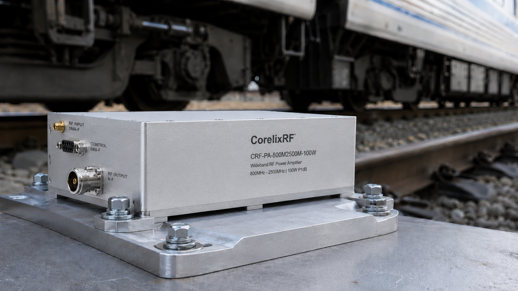
Intermittent signal drops severely plague rail networks. Commercial amplifiers fail constantly under mechanical fatigue during transit. Our engineered hardware mitigates physical breakdown entirely. With two decades solving field anomalies, CorelixRF delivers guaranteed operational stability. System integrators require factory direct solutions addressing root causes directly.
1. Why Do High-Speed Rail RF Systems Experience Intermittent Drops?
Diagnosing Intermittent Signal Losses
Intermittent signal degradation frustrates railway maintenance crews relentlessly. You might be wondering why standard RF modules fail constantly aboard moving trains. Bogies hitting rail expansion joints at 300km/h generate brutal 15Hz shockwaves. These physical waves travel directly into rack-mounted electronics without dampening. Standard chassis designs absorb mechanical energy poorly during rapid transit. Over months, continuous shaking compromises physical connections internally. We routinely examine returned hardware exhibiting bizarre communication behavior. Technicians check parameters expecting normal thermal wear initially. Instead, testing reveals physical separation within coaxial transmission lines. A simple visual inspection rarely exposes microscopic material damage. Engineers must deploy advanced diagnostic tools immediately. Utilizing spectrum analyzers reveals momentary power fluctuations matching train acceleration profiles. Return loss measurements fluctuate erratically across varying vibration frequencies. These symptoms point toward physical instability rather than component aging. Such physical degradation ruins overall link budget margins completely. Our manufacturing experience proves commercial solutions lack necessary rigidness.
Analyzing Network Analyzer Responses
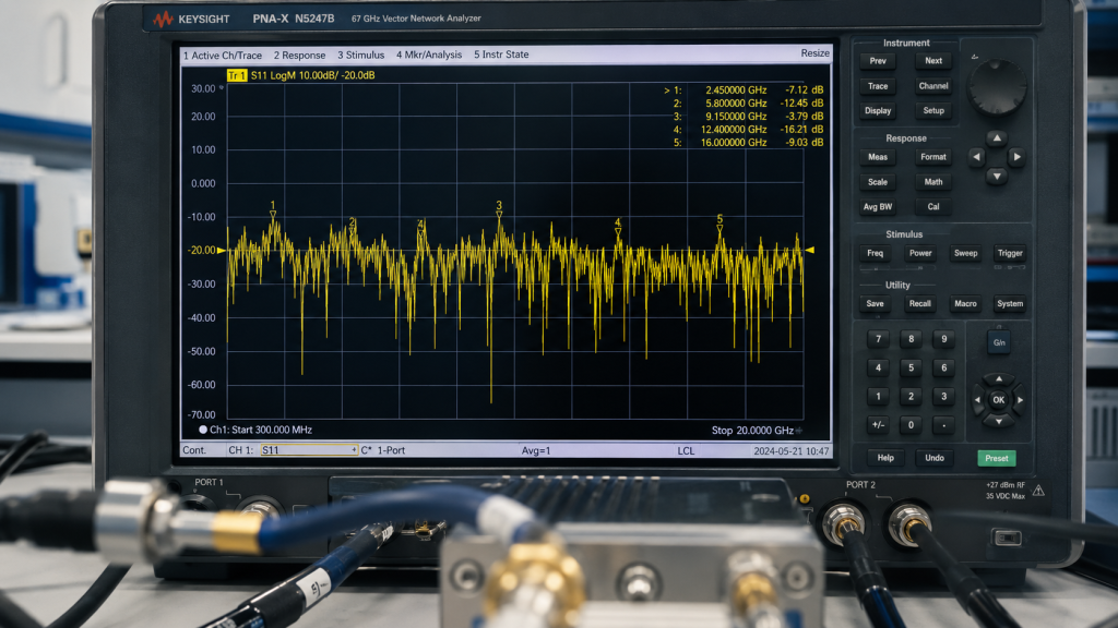
Field technicians rely heavily upon vector network analyzers during troubleshooting. What’s the real story? An unstable VNA trace indicates severe physical disruption internally. Sweeping across broadband ranges exposes localized impedance mismatches immediately. High-frequency signals reflect sharply against compromised mechanical joints. When a train car vibrates, loose connections shift slightly. This shifting alters parasitic capacitance across conductive paths momentarily. A network analyzer captures these transient reflections accurately during testing. We observe VSWR spikes triggering system protection mechanisms abruptly. A solid connection maintains S-parameters even when passing pantographs induce severe mechanical chassis shaking. Conversely, fractured joints create noisy response patterns during live measurements. Equipment operators interpret these fluctuations incorrectly as thermal issues often. They replace cooling fans without solving fundamental physical problems. Proper diagnosis requires understanding mechanical resonance and stress concentration. Our factory analyzes hundreds of failure cases annually. We design mitigation strategies addressing root physical causes directly.
Common Rail Vibration Symptoms
| Symptom | Typical Cause | Diagnostic Tool |
| Power Fluctuation | Fractured Solder | Spectrum Analyzer |
| Return Loss Spike | Loose Connector | VNA |
| System Reboot | Power Pin Wear | Multimeter |
2. How Does Low-Frequency Vibration Compromise Mechanical Integrity?
Connector Fretting and Back-Off
Continuous mechanical movement destroys threaded coaxial interfaces over time. But here’s the kicker. Standard torque applications cannot withstand persistent 10Hz physical shaking. Micro-fretting occurs between mated conductive surfaces continuously during transit. This abrasive action strips away protective plating materials rapidly. Bare copper oxidizes quickly, increasing contact resistance heavily. Eventually, threaded nuts vibrate loose completely under extreme acoustic stress. Engineers find SMA interfaces completely disconnected inside trackside equipment racks. We specify exact torque values for every assembled unit. Our CRF-PA-300M1700M-100W model utilizes an SMA-Female RF input connector. For output connections, an N-Female RF connector provides robust mating. These specific choices minimize fretting risks during railway operation. Larger N-type threads offer superior mechanical gripping strength against shockwaves. Proper installation requires specialized torque wrenches avoiding over-tightening. Factory direct solutions incorporate locking compounds on critical interface threads. This prevents unwanted loosening without compromising electrical grounding paths.
PCB Flex and Solder Fatigue
Printed circuit boards flex violently under continuous resonant frequencies. This gets highly interesting. Rigid solder joints connecting heavy power transistors crack predictably. SMT components suffer immense shear forces during chassis bending. Micro-cracks propagate slowly through solder fillets completely unseen. Eventually, complete separation breaks electrical continuity entirely. High-power RF amplifiers require massive transistors for signal amplification. These large packages possess heavy mass aggravating vibration effects. When resonance hits, bare boards act like trampolines. Our engineering team addresses this via massive structural reinforcement. We mount circuit boards firmly onto thick metal bases. This eliminates destructive flexing across critical high-frequency sections. Long-term reliability demands eliminating mechanical strain on solder joints. Factory direct testing simulates years of rail travel vibrations. We guarantee performance under harsh physical environments globally.
3. What Happens Thermally When Micro-Solder Joints Crack?
Impedance Mismatches and Reflections
A fractured solder joint disrupts characteristic impedance severely. Look closely at the data. High-frequency currents travel strictly along surface skin layers. A crack forces current paths through highly resistive paths. This abrupt change creates massive signal reflections internally. Forward power bounces backward toward active amplifying stages. Reflected energy generates dangerous standing waves along transmission lines. Our specified model operates across a 300-1,700 MHz frequency range. Across this wideband spectrum, matching remains critical for stability. The input VSWR maintains a maximum 1.8:1 ratio. Output VSWR stays strictly below 2.0:1 under normal conditions. A crack quickly pushes these ratios beyond safe operational limits. High VSWR triggers protection circuits shutting down transmission instantly. Continuous tripping indicates underlying physical degradation within amplifier modules. Engineers must recognize thermal symptoms stemming from mechanical failures.
Localized Heat Generation Dynamics
Reflected energy converts directly into localized thermal spots. Ready for the good part? Dissipating unwanted heat challenges any confined system architecture. A micro-crack acts as a tiny resistive heating element. Hundreds of watts channel through compromised metallic junctions. Temperatures spike rapidly exceeding component maximum ratings. Thermal runaway destroys expensive power transistors within seconds. Our CRF-PA-300M1700M-100W delivers 100 W rated output power. Managing this energy requires pristine conductive pathways constantly. The module operates within extreme temperatures from -40°C up until +85°C. Surviving such extremes demands flawless internal thermal management. We employ specialized soldering profiles guaranteeing void-free connections. Factory quality control utilizes X-ray inspection confirming joint integrity. Proper thermal dissipation relies entirely on solid mechanical bonding. Any physical separation degrades cooling efficiency drastically.
CRF-PA-300M1700M-100W Interface Specs
| Port Type | Connector | Typical VSWR |
| RF Input | SMA-Female | $\le1.8:1$ |
| RF Output | N-Female | $\le2.0:1$ |
| Control | DB9 | N/A |
4. How Does Chassis Design Prevent PCB Flexing?
Advanced Enclosure Engineering
Protecting fragile electronics requires robust outer shell construction. Let’s dive right in. A weak chassis transfers external vibrations directly inward. Flimsy metal bends under constant low-frequency acoustic pressure. We utilize heavy-duty machined aluminum housings for maximum rigidity. The package size measures exactly 200 x 158 x 25 mm. This compact structure inherently resists low-frequency resonant modes effectively. Thick walls prevent any bending forces from reaching circuit boards. Our engineers calculate optimal mounting hole placements minimizing strain. The mechanical outline drawing shows these integration reference points clearly. Securing the module firmly against flat surfaces eliminates vibration amplification. Railway environments punish weak structural designs unmercifully daily. A solid metal block provides excellent environmental isolation. We eliminate a primary cause of solder fatigue completely.
Internal Cavity Resonance Mitigation
Internal spaces within amplifiers create unexpected engineering problems. Here is the truth. Electromagnetic resonance inside cavities degrades high-frequency performance. We design internal shielding walls separating sensitive gain stages. These walls serve dual purposes adding massive structural support. They tie top covers directly down onto base plates firmly. This creates a monolithic block impervious against mechanical shaking. The module maintains a maximum weight of 1.4 kg. Keeping mass low reduces momentum forces during sudden train braking. Heavy components receive extra structural epoxy adhesives during assembly. This prevents heavy inductors from tearing pads off printed boards. Our factory prioritizes physical robustness alongside electrical specifications. Surviving field deployments requires aggressive mechanical engineering approaches.
5. Can Stable Output Power Be Maintained Across 300-1,700 MHz?
Broadband Amplification Challenges
Wideband applications challenge traditional amplifier matching networks severely. You should note this. Designing circuits covering multiple octaves requires complex impedance transformations. Mismatches across wide bands cause uneven gain profiles. Our hardware achieves remarkable consistency across designated spectrums. The device delivers an impressive typical gain reaching 50 dB. Gain flatness stays rigorously controlled below 1.8dB. A representative swept measurement confirms this performance clearly. We utilize advanced wideband matching topologies reducing internal reflections. Maintaining stable output power requires robust component selection. Train communication systems demand continuous coverage without dead zones. Our equipment supports critical data links seamlessly across frequencies. Field engineers appreciate predictable performance during complex system integrations.
CW and Saturated Operation
Continuous wave operations stress active components continuously without relief. Consider this fact. Pulsed systems allow thermal cooling between transmission bursts. CW signals generate constant heat loads demanding superior cooling. The output power type operates strictly in CW/Saturated modes. Driving the module into saturation maximizes power efficiency. Input drive for rated output typically ranges from 0 dBm. Maximum input drive must not exceed 8 dBm. We protect sensitive input stages against accidental overdrive conditions. Harmonics remain strictly controlled at -10dBc. Spurious emissions stay exceptionally low below -60dBc. This clean spectral output prevents interference affecting adjacent receivers. CorelixRF guarantees these parameters across all production units.
Thermal and Environmental Specifications
| Parameter | Minimum | Maximum |
| Operating Temperature | -40°C | +85°C |
| Storage Temperature | -40°C | +85°C |
| Rated Output Power | 100 W | N/A |
6. How Does Current Consumption Behave Under Mismatched Conditions?
Managing 28 VDC Power Systems
Industrial environments utilize standard DC power buses routinely. Here is why that matters. Railway infrastructure often supplies fluctuating direct current voltages. Our modules require a nominal supply voltage of 28 VDC. Stable voltage regulation prevents unwanted amplitude modulation artifacts. Current consumption remains remarkably efficient during continuous operation. The device draws a maximum current of 14 A. High current traces on printed boards require adequate copper thickness. We utilize heavy copper layouts minimizing resistive voltage drops. This guarantees active transistors receive full bias voltages consistently. Proper grounding techniques eliminate ground loops causing interference. We tie all ground planes directly onto metallic chassis structures. This provides low-impedance return paths maximizing overall stability.
Current Spikes and System Protection
Antenna mismatches cause immediate operational current surges. What does this mean for you? When a connector loosens, reflected power alters transistor loading. This impedance shift forces devices demanding higher supply currents. Left unchecked, excessive current destroys power supply units quickly. We integrate fast-acting current limiting circuits within our designs. These mechanisms protect hardware during accidental short circuits. High-speed rail environments present unpredictable antenna loading scenarios. Ice accumulation on train roof antennas alters return loss parameters drastically during winter transits. Our amplifiers survive these harsh realities without permanent damage. Factory testing simulates severe load mismatches analyzing recovery times. We guarantee systems return online immediately after fault removal. Reliability depends heavily upon surviving unexpected electrical stress.
7. What Are Reliable Connector Choices for Vibrating Environments?
Evaluating SMA and N-Type Interfaces
Selecting correct physical interfaces determines long-term field success. Let’s face it. Weak connectors fail rapidly under continuous industrial vibration. The RF input utilizes a precision SMA-KFD46 connector. This interface provides excellent high-frequency characteristics inside compact footprints. The RF output features a rugged N-Female interface. N-type connectors handle high power levels without dielectric breakdown. Their massive threaded bodies resist mechanical loosening effectively. Our factory applies specific torque recommendations during final assembly. We advise integrators against mixing incompatible connector metals. Dissimilar metals cause galvanic corrosion accelerating physical joint degradation. Proper sealing tapes protect external connections against moisture ingress. Field reliability requires meticulous attention addressing seemingly minor details.
Control Interfaces and Monitoring
Modern amplifiers require continuous status monitoring capabilities. This changes everything. Blind operation prevents preemptive maintenance before catastrophic failures occur. The control interface utilizes a standard DB9 connector. This allows easy integration alongside legacy industrial control systems. Pinouts provide access monitoring forward power and reflected energy. Temperature sensors report internal chassis conditions directly outward. A sudden temperature rise indicates potential cooling system failures. Monitoring allows operators disabling transmitters preventing total hardware destruction. We provide custom control interfaces matching specific client requirements. Our engineering team provides feasibility reviews within 48 hours. Customization guarantees seamless integration across diverse railway networks.
Key Electrical Performance Data
| Parameter | Typical Value | Maximum Value |
| Gain | 50 dB | 51 dB |
| Gain Flatness | N/A | $\le1.8$ dB |
| Harmonics | -12 dBc | $\le-10$ dBc |
8. How Effective Are Air Cooling Strategies for Confined Installations?
Air Cooling Dynamics
Heat dissipation dictates overall lifespan for high-power electronics. You might wonder. Can passive techniques manage massive thermal loads adequately? The specified cooling method utilizes standard air cooling. High-speed trains offer unique airflow opportunities during transit. Equipment shelters often utilize forced air circulation systems. Our module designs maximize surface area transferring heat efficiently. Flat base plates require high-quality thermal interface materials. Integrators must apply compounds evenly avoiding trapped air pockets. Air acts as an incredible insulator ruining thermal transfer. We recommend specific torque patterns bolting modules onto heatsinks. Proper mounting guarantees maximum metal-to-metal contact areas. Efficient thermal paths keep transistor junction temperatures safely low.
Managing Extreme Temperature Ranges
Railway deployments face brutal environmental temperature swings. Here is the bottom line. Equipment parked outdoors freezes overnight and bakes midday. Surviving requires materials handling immense thermal expansion coefficients. The module guarantees performance down reaching -40°C. It operates flawlessly up hitting +85°C maximums. Repeated thermal cycling cracks weak solder joints inevitably. We employ specialized alloys resisting fatigue during expansion phases. Component selection prioritizes wide temperature ratings aggressively. Our factory conducts rigorous environmental stress screening routinely. Burn-in processes eliminate early infant mortality failures before shipping. We deliver hardware proven capable enduring harsh climates continuously.
9. Does Form Factor Impact Mechanical Resonance Frequencies?
Dimension Analysis and Resonance
Physical dimensions dictate inherent mechanical resonance characteristics directly. Think about it. Every object possesses natural frequencies vibrating violently when stimulated. Train vibrations range typically between ten and fifty hertz. The package dimensions measure exactly 200 x 158 x 25 mm. This specific aspect ratio pushes natural resonances higher. High resonant frequencies avoid overlapping with typical rail vibrations. We simulate mechanical structures utilizing advanced 3D modeling software. Analyzing modes prevents destructive energy buildup within critical areas. The mechanical drawing remains kept fully visible facilitating dimensional reviews. This assists integrators designing custom mounting brackets easily. Proper structural planning prevents disastrous field failures later.
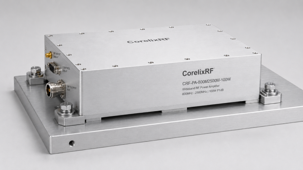
Mounting a 1.4 kg Module securely
Mass distribution affects how forces travel through equipment racks. Let’s get real. Securing heavy modules requires substantial mechanical engineering consideration. The device maintains a maximum weight staying 1.4 kg. Four sturdy mounting holes distribute stresses evenly across platforms. We specify high-tensile steel bolts replacing cheap hardware. Nylon locking nuts prevent loosening under persistent acoustic vibrations. Washers distribute clamping forces protecting aluminum chassis surfaces. Our engineers assist clients designing optimal mechanical integration layouts. We understand physical forces tearing equipment apart violently. Reliable communication networks depend upon unbreakable physical foundations. CorelixRF delivers factory direct technology solving real engineering problems.
Connection Interfaces Overview
| Interface | Connector Type | Function |
| RF In | SMA-KFD46 | Low-power signal input |
| RF Out | N-Female | High-power transmission |
| Control | DB9 | Telemetry and commands |
10. How Can We Verify Long-Term Reliability and Quality Compliance?
Compliance and Quality Framework
Global deployments demand strict adherence towards international quality standards. This matters immensely. Unverified hardware introduces unacceptable risks entering critical infrastructure networks. Our products maintain strict RoHS Compliant manufacturing statuses. We hold detailed CE/FCC regulatory approvals globally. Factory operations follow stringent ISO 9001 management protocols. For defense applications, we meet GJB 9001C requirements fully. These certifications guarantee consistent manufacturing precision across batches. Every amplifier undergoes rigorous automated testing before packaging. Traceability guarantees we track individual components tracing potential defects. Quality frameworks prevent substandard materials from compromising final assemblies. B2B clients demand proof backing technical marketing claims. We deliver engineering truth backed by solid documentation.
MTBF and System Assessment
Mean time between failures dictates maintenance schedules and budgets. Here is the best part. Highly reliable systems reduce operational expenses drastically. MTBF reliability data remains available upon direct request. Environmental validation data supports complex project reviews effectively. We encourage integrators requesting these detailed engineering reports. Analyzing lifetime data proves our designs outlast competitor offerings. Railway authorities demand proof guaranteeing decades of operation. CorelixRF stands ready providing deep technical transparency always. Our products serve radar and communication systems flawlessly worldwide. Stop replacing broken equipment and deploy engineered solutions today.
Field Troubleshooting: Hidden Failures in High-Speed Rail Communications – Long-term Low-Frequency Vibration Causing Connector Loosening and Micro-Solder Joint Cracking. Mechanical integrity defines electrical performance completely within harsh vibrating environments. Deploying the CRF-PA-300M1700M-100W eliminates hidden physical degradation permanently. Contact our engineering team obtaining validation data immediately. Protect your communication infrastructure today.
- Q1: What is the primary cause of intermittent RF drops in trains?
- Long-term low-frequency vibration causes connector back-off and micro-solder joint cracking.
- Q2: How does the CRF-PA-300M1700M-100W handle thermal dissipation?
- It utilizes a robust aluminum chassis optimized for air cooling across wide temperatures.
- Q3: Why do VSWR alarms trigger during mechanical vibration?
- Fractured joints create impedance mismatches, causing signal reflections and high VSWR.
- Q4: Can I monitor the amplifier status remotely?
- Yes, a DB9 control interface provides necessary telemetry for system monitoring.
- Q5: What certifications verify the quality of these amplifiers?
- Our products are RoHS Compliant, CE/FCC certified, and follow ISO 9001 standards.