
Troubleshooting High-Speed Rail Communication Signal Anomalies demands absolute engineering precision. Sudden RF power drops trigger constant alarms during moving train operations. Random system failures destroy transit network reliability completely causing immense downtime. Replacing random hardware modules without understanding physics wastes valuable maintenance hours. We offer a proven hardware architecture eliminating these exact mechanical failures. CorelixRF manufactures heavy-duty RF power amplifiers solving complex mechanical problems daily. Our twenty years of factory experience provides unmatched technical frontline credibility. We rely strictly upon objective microwave performance data for every decision.
1. What are the Frontline Symptoms of High-Speed Rail Communication Signal Anomalies?
Identifying Immediate Link Degradation
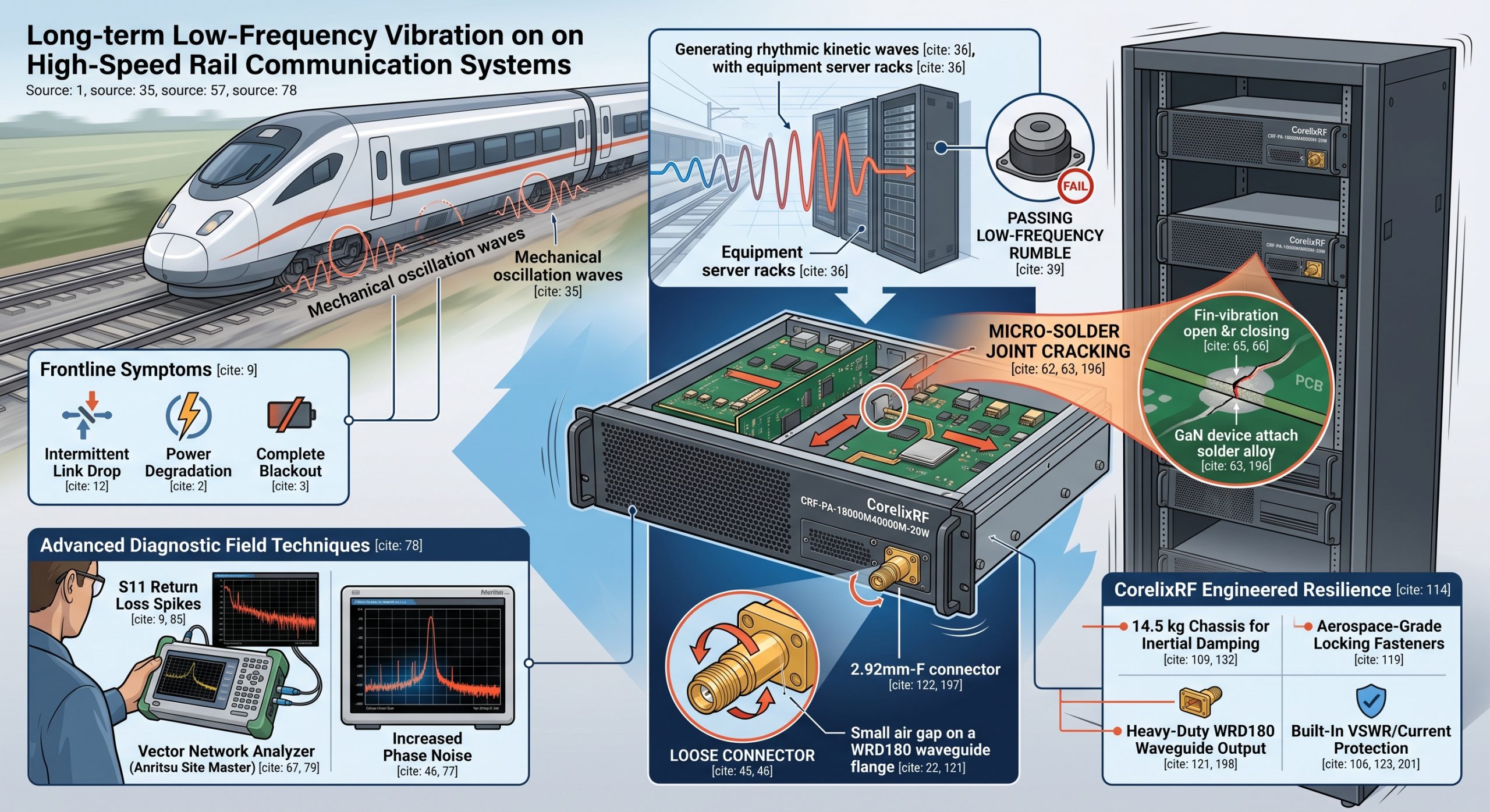
Engineers dread seeing sudden Return Loss spikes on field diagnostic monitors. Moving passenger trains generate immense continuous kinetic energy daily during transit. This kinetic energy transfers directly into mounted telecommunications equipment cabinets constantly. System operators notice intermittent data link drops during normal transit operations. Sudden VSWR alarms flash across vehicle command screens unexpectedly halting progress. These High-Speed Rail Communication Signal Anomalies halt transit protocols immediately requiring intervention. You check coaxial cables but find no obvious external physical damage. Standard diagnostic software reveals nothing except random packet loss dropping events. It gets worse, because random intermittent faults confuse inexperienced maintenance crews. An inexperienced technician might swap transceiver modules hoping for immediate relief. However, replacing modules without understanding physics wastes extremely valuable maintenance hours. True hardware debugging requires examining physical layer interconnects very closely onsite. RF power amplifiers endure continuous mechanical stress during violent train acceleration. Loose WRD180 waveguide flanges create tiny air gaps destroying impedance matching. Reflected microwave energy damages sensitive internal GaN transistor components severely eventually. Consider a passenger network handling thousands of concurrent wireless data sessions. A dropped packet stream ruins critical remote dispatching commands almost instantaneously. We must treat transit environments differently than static office building deployments. Industrial systems demand rigorous physical inspections targeting microscopic hardware transmission failures. Engineers must measure torque values applied upon every single coaxial connector. Proper torque prevents sudden catastrophic RF mismatches during continuous high-speed travel. High-speed data networks require flawless physical continuity across all hardware interfaces. Ignoring these mechanical realities guarantees future catastrophic system failures and downtime.
Symptom Classification
| Fault Type | Field Indicator | Probable Physical Cause |
| Intermittent Link Drop | High Error Rate | Waveguide flange separation |
| Power Degradation | VSWR Alarm | Loose 2.92mm-F connector |
| Complete Blackout | Zero Output Power | Severed internal power trace |
2. What Causes Long-Term Low-Frequency Vibration to Degrade RF Systems?
Mechanical Resonance and Hardware Fatigue
Trains rolling across steel tracks generate continuous rhythmic mechanical oscillation waves. Constant movement produces specific low-frequency kinetic waves penetrating equipment server racks. These mechanical waves match natural resonant frequencies of internal circuitry boards. You might be wondering, why standard rubber shock vibration mounts fail. Standard commercial isolators absorb high-impact shocks but ignore low-frequency kinetic rumbling. Continuous rumbling flexes printed circuit boards millions of times daily unceasingly. This constant flexing stresses every single mounted passive component incredibly heavily. Heavy capacitors acting like microscopic pendulums tear copper traces apart slowly. High-Speed Rail Communication Signal Anomalies originate from these invisible microscopic fractures. Rigid coaxial cables act as levers pulling against fragile exterior connectors. Torque applied at those interfaces loosens retaining nuts over several weeks. A loosened 2.92mm-F connector introduces severe phase noise into microwave transmissions. We observe degraded gain flatness exceeding our normal ±6dB limits rapidly. Engineers often underestimate destructive power originating from continuous low-amplitude physical shaking. Metal fatigue accumulates silently within copper structures until catastrophic electrical failure. We must analyze these vibration profiles using specialized recording field instruments. Capturing real-world kinetic data allows us engineer better structural dampening architectures. Standard laboratory bench tests completely fail replicating these dynamic kinetic stresses. You need massive structural integrity for surviving such brutal kinetic conditions.
Fatigue Factor Analysis
| Stress Source | Component Impacted | Resulting RF Degradation |
| Low-Frequency Rumble | Heavy Capacitors | Power supply noise injection |
| Thermal Cycling | GaN Die Attach | Thermal runaway and burnout |
| Cable Torque | 2.92mm-F Input | Severe phase distortion |
3. What is the Physical Mechanism Behind Micro-Solder Joint Cracking?
Thermal Cycling Combined with Kinetic Stress
Understanding High-Speed Rail Communication Signal Anomalies requires examining deep metallurgical properties. Solder joints endure both mechanical shaking and extreme ambient thermal cycling. RF power amplifiers consume 450W generating significant internal heat loads constantly. Heating expands metallic components while cooling contracts those exact same structures. What’s the real story? This continuous cycle creates immense sheer forces. Microscopic cracks initiate at rigid interconnections between GaN devices and substrates. Low-frequency shaking accelerates crack propagation through tin-lead or lead-free solder alloys. Eventually, complete separation occurs leaving an intermittent electrical connection behind permanently. When vibration pushes fractured surfaces together, microwave signals pass through normally. A millisecond later, shaking pulls those surfaces apart causing immediate failure. You see wild fluctuations on an Anritsu Site Master instantly onsite. We measure these erratic impedance shifts during simulated transit validation tests. Such microscopic failures explain why static bench validation tests pass perfectly. A cracked joint acts like a highly variable parasitic series capacitor. This parasitic capacitance destroys high-frequency 40,000 MHz signal integrity completely during operation. We utilize advanced X-ray imaging for detecting these internal microscopic fractures. Only robust mechanical damping prevents these destructive kinetic forces from occurring. Engineers must select equipment featuring heavy mass and secure internal fastening.
Diagnostic Instrument Pairings
| Failure Mode | Recommended Instrument | Key Metric Monitored |
| Micro-cracking | Portable VNA | S11 Return Loss |
| Trace Separation | Oscilloscope | DC Voltage Drop |
| Connector Loosening | Spectrum Analyzer | Phase Noise / Spurious |
4. How Do We Use Instruments for Isolating High-Speed Rail Communication Signal Anomalies?
Advanced Diagnostic Field Techniques
Deploying standard multimeters proves completely useless when hunting intermittent microwave faults. Technicians must carry portable Vector Network Analyzers into moving train cars. Ready for the good part? We capture real-time scattering parameters continuously. Connecting a Keysight FieldFox directly towards suspect transmission lines helps immensely. We set sweep times extremely fast capturing split-second impedance changes instantly. A technician watches S11 return loss graphs while passenger trains accelerate. High-Speed Rail Communication Signal Anomalies manifest as sudden S11 curve collapses. Sudden spikes reaching -10dB indicate severe connector separation events very clearly. We also deploy spectrum analyzers monitoring harmonic content during travel operations. Damaged output matching networks generate elevated spurious emissions exceeding acceptable limits. By correlating vibration events with sudden RF drops, we isolate culprits. Our engineers never guess; they let physical instrument data dictate strategies. We mount accelerometers directly onto chassis monitoring exact shaking kinetic frequencies. Comparing accelerometer data with phase noise plots reveals structural weaknesses perfectly. This rigorous diagnostic methodology guarantees accurate field troubleshooting every single time. Finding root causes quickly prevents unnecessary equipment replacement and maintenance costs.
Commercial vs Industrial Design
| Feature | Standard Commercial | Industrial CorelixRF |
| Enclosure | Palm-sized module | 19” 3U Rack-mount |
| Cooling | Passive external sink | Active forced air cooling |
| Protection | None | Built-in VSWR/Current |
5. What are Common Pitfalls in Standard Commercial RF Amplifier Selection?
The Danger of Undersized Modules
Many system integrators select tiny palm-sized modules hoping for space convenience. Small enclosures lack adequate mass damping against continuous operational kinetic energy. Lightweight housings transfer shaking directly into fragile internal RF matching networks. This is where it gets interesting, miniaturized designs compromise integrity fundamentally. They cram dense circuitry together without proper mechanical stress relief zones. High-Speed Rail Communication Signal Anomalies thrive inside these cramped fragile spaces. Those tiny boxes rely on external heat sinks lacking proper airflow. Insufficient cooling causes localized hot spots degrading GaN transistor lifespans rapidly. Standard commercial units also use cheap connectors incapable of handling torque. A generic SMA port fails quickly under heavy coaxial cable tension. Furthermore, standard units lack integrated over-voltage or over-current protection mechanisms entirely. When severe impedance mismatches occur, unprotected commercial amplifiers burn out instantly. True B2B applications require industrial formats like 19-inch 3U rack-mount units. A heavy 14.5 kg chassis provides necessary inertial resistance against shaking. Do not gamble your network reliability upon cheap consumer-grade amplification hardware.
Mechanical Specifications
| Parameter | CorelixRF Specification | Engineering Benefit |
| Package Size | 19” 3U Rack-mount | Fits standard rail bays |
| Total Weight | 14.5 kg | Inertial kinetic damping |
| Output Port | WRD180 Waveguide | Resists structural flexing |
6. How Does the CRF-PA-18000M40000M-20W Resolve Vibration-Induced Failures?
Engineered Resilience and Industrial Protection
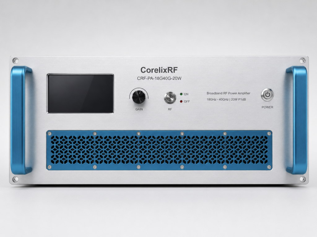
We engineered our CRF-PA-18000M40000M-20W specifically combating severe transport kinetic environments daily. This system delivers 20W rated output across 18,000–40,000 MHz frequencies continuously. Now pay attention, we abandoned fragile module concepts entirely for durability. Our design utilizes a robust 19-inch 3U rack-mount chassis formatting explicitly. Heavy mass naturally dampens high-frequency kinetic energy reaching sensitive internal components. We secure internal PCBs using aerospace-grade locking fasteners and stress loops. High-Speed Rail Communication Signal Anomalies disappear when interconnects remain firmly seated. We utilize heavy-duty WRD180 waveguide output flanges preventing structural mechanical separation. The input utilizes a high-reliability 2.92mm-F connector withstanding severe rotational torque. Built-in protection circuits monitor over-voltage, over-temperature, and over-current conditions completely continuously. If an external antenna gets damaged, optional over-drive protection activates quickly. This architecture ensures GaN transistors survive catastrophic external VSWR events perfectly. CorelixRF manufactures these units focusing strictly upon long-term operational survival metrics. We provide exact mechanical drawings ensuring perfect integration into equipment racks.
Validation Test Matrix
| Test Category | Methodology | Pass Criteria |
| Vibration | 6-Axis Shaker Table | No RF power drop |
| Thermal | 0°C to 50°C Cycling | Gain flatness < 6dB |
| Electrical | Continuous 450W Load | Zero component failure |
7. What is the Role of the 19-Inch 3U Rack-Mount Chassis in High-Speed Rail Environments?
Mass Damping and Thermal Dissipation
You cannot defeat physics using marketing adjectives or cheap thin enclosures. A 14.5 kg chassis provides immense inertial resistance against sudden movements. Truth be told, heavier systems vibrate much less than lightweight alternatives. This rack-mount format bolts directly into standard railway communication equipment bays. We integrated high-volume air cooling fans directly within this massive structure. Internal ambient temperatures remain stable even when drawing 450W power constantly. Stable temperatures prevent thermal expansion from fatiguing critical micro-solder joints internally. Our AC 220V power supply utilizes industrial-grade vibration-resistant electrolytic capacitors exclusively. These massive chassis dimensions allow generous spacing between high-power RF stages. Separation prevents cross-talk and maintains a pure noise floor quite effortlessly. Eliminating High-Speed Rail Communication Signal Anomalies requires this brute-force structural approach. Industrial deployments demand hardware matching exact physical reality regarding moving trains. This metal enclosure acts as a mechanical fortress protecting sensitive circuits. CorelixRF designs focus relentlessly upon these practical frontline engineering truths daily.
8. What are the Specific Electrical Characteristics of the CRF-PA-18000M40000M-20W?
Uncompromising Microwave Performance Metrics
Raw power means absolutely nothing without extreme signal fidelity and reliability. Our system maintains a minimum 43dB gain covering wideband Ka spectrums. Here is the kicker, we guarantee an input VSWR below 2:1. Excellent input matching prevents signal reflections from damaging preceding transceiver stages. We maintain harmonic distortion strictly below -10dBc ensuring clean transmission spectrums. Control interfaces include standard RS485 and LAN ports for remote monitoring. These digital interfaces let engineers track temperatures without opening train cabinets. An adjustable gain range reaching 15dB allows precise link budget tuning. High-Speed Rail Communication Signal Anomalies cannot hide from our diagnostic telemetry. Operators adjust output power dynamically compensating for varying harsh weather conditions. This precise control ensures maximum uptime across vast geographical railway networks. Our equipment operates perfectly across temperature ranges spanning 0°C through 50°C. We provide exact test data confirming these electrical parameters upon request. You receive hardware matching its published specification sheet completely without deviation.
9. How Do We Validate High-Speed Rail Communication Signal Anomalies in the Lab?
Rigorous Simulation and Factory Testing
We refuse releasing products without brutal physical validation testing beforehand always. Our technicians strap every prototype onto six-axis electro-dynamic shaker tables securely. Let me clarify, we simulate exact kinetic profiles recorded during journeys. We subject amplifiers towards hours of randomized low-frequency severe shaking profiles. Simultaneously, environmental chambers cycle temperatures between 0°C and 50°C very aggressively. We monitor RF output power continuously while massive machines shake violently. Any unit dropping below its 20W rated output fails our inspection. We perform X-ray inspections checking micro-solder joints after completing vibration tests. This rigorous process guarantees zero internal fracturing before shipping hardware out. High-Speed Rail Communication Signal Anomalies only exist when manufacturers skip testing. CorelixRF maintains ISO 9001 and GJB 9001C compliance frameworks ensuring consistency. We supply actual test pattern files assisting your project review phase. You gain complete confidence knowing each unit survived actual physical torture. Our engineering truth relies entirely upon measurable, repeatable factory laboratory data.
10. What is the Final Engineering Consensus on High-Speed Rail RF Deployments?
Securing the Future of Transit Telemetry
Ignoring mechanical realities guarantees catastrophic microwave system failures eventually for sure. Standard commercial modules cannot survive continuous kinetic punishment indefinitely under stress. The bottom line is, physics dictates hardware survival across harsh environments. Industrial applications require industrial-grade mass, dedicated cooling, and secure waveguide flanges. High-Speed Rail Communication Signal Anomalies vanish when you deploy proper architecture. We build equipment designed specifically handling continuous violent physical abuse successfully. Our GaN technology combined with structural damping creates unbreakable communication links. Engineers must stop treating transit networks like static laboratory bench setups. Implementing proper hardware eliminates late-night maintenance calls and passenger transit delays. You secure your reputation by installing components built for actual reality. Upgrading towards ruggedized 19-inch enclosures provides massive long-term operational cost savings. We remain committed providing objective facts driving your future engineering decisions. Stop fighting mysterious intermittent faults and install verified industrial amplification hardware. CorelixRF stands ready supplying units meeting your exact deployment schedule requirements.
Troubleshooting High-Speed Rail Communication Signal Anomalies demands rigorous physical examination techniques. We demonstrated how mechanical vibration destroys fragile interconnects creating intermittent faults. Our CRF-PA-18000M40000M-20W provides a robust 3U rack-mount solution preventing these failures. Evaluate your current hardware specifications and demand industrial-grade physical reliability today. Contact CorelixRF directly for detailed testing data and project review assistance.
Q1: What is the CRF-PA-18000M40000M-20W?
This model represents a ruggedized wideband RF power amplifier delivering 20W. It covers frequencies spanning 18,000 through 40,000 MHz flawlessly for operations. CorelixRF manufactures this unit inside a heavy 19-inch 3U rack-mount chassis.
Q2: How does long-term low-frequency vibration affect RF systems?
Vibration causes severe mechanical fatigue across internal circuit boards and connectors. This kinetic stress snaps micro-solder joints creating intermittent impedance mismatch failures. Heavy structural mass damping prevents these destructive High-Speed Rail Communication Signal Anomalies.
Q3: What output connector does this amplifier utilize?
We utilize a heavy-duty WRD180 waveguide flange for microwave power output. This robust interface prevents mechanical separation under extreme rotational torque conditions. It ensures reliable transmission continuity despite constant environmental kinetic shaking events.
Q4: What protection mechanisms exist inside this unit?
Our design includes built-in protection against over-voltage, over-temperature, and over-current faults. We also offer optional over-drive protection saving internal GaN transistor components. These digital circuits monitor hardware health continuously via RS485 and LAN interfaces.
Q5: Why choose a 14.5 kg 3U rack-mount over smaller modules?
Heavy mass provides critical inertial damping against continuous railway kinetic energy. Smaller lightweight modules transfer destructive vibration directly into sensitive internal electronics. A massive structural chassis ensures thermal stability and long-term mechanical survival.
Translate rugged-site symptoms into a complete RF-chain review
Rugged RF issues often combine grounding, vibration, thermal range, connector retention, signal source stability and amplifier power margin. Share the site condition and acceptance evidence needed before choosing a platform.
Recommended next step: send the operating band, output power target, duty cycle, load condition, control interface, protection or thermal limits and required FAT documents. CorelixRF can review this How to Prevent High-Speed Rail RF Anomalies in Transit? requirement against standard RF amplifier platforms, RF front-end options and controlled customization paths.