
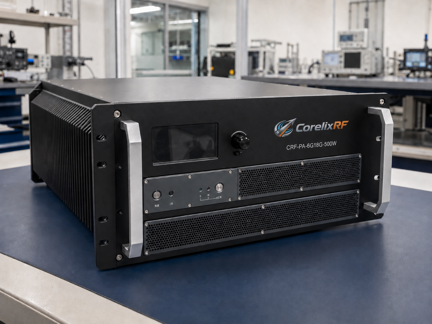
Airborne RF front-end systems drop output power abruptly mid-flight. Intermittent signal loss triggers immediate mission failure constantly. Such faults evade standard bench testing procedures entirely. Here is the deal: Engineering rigorous mechanical matching eliminates these specific hardware failures directly. The CRF-PA-6000M18000M-500W solves this mechanical resonance issue completely. CorelixRF engineers have evaluated airborne equipment across three decades of rigorous manufacturing. Our technical personnel understand physical engineering truth deeply.
1. Why Do Standard RF Amplifiers Fail In Airborne Vibration Environments?
Microscopic structural degradation parameters
You might be wondering: What happens inside standard commercial hardware during harsh flight operations? Rotor wash induces persistent low-frequency mechanical shaking continuously. Standard rack-mount chassis designs lack necessary internal damping materials. Continuous physical shaking transfers directly toward delicate internal RF components. High-power modules experience severe structural fatigue very quickly. Engineers often overlook mechanical resonance during initial schematic drafting. They focus exclusively upon electrical parameters like gain flatness. Physical reality asserts dominance during actual airborne field deployment. Systems utilizing standard fifty-ohm traces suffer microscopic fracturing invariably. Airborne electronic warfare pods demand specialized structural engineering constantly. CorelixRF understands this exact reality through extensive manufacturing history. Our mainland China factory produces hundreds of hardened amplifier units monthly. We analyze failed third-party systems arriving for diagnostic evaluation. Basic mounting brackets shear off under sustained acoustic pressure. Standard commercial fans disintegrate rapidly when facing varying altitudes. Military-grade platforms require completely different mechanical construction philosophies. RF components fracture without proper structural vibration isolation techniques. The CRF-PA-6000M18000M-500W design prevents these common mechanical failure chains. Every single solder joint requires precise evaluation regarding acoustic stress.
Amplifier Base Parameters
| Parameter | Value | Test Conditions |
| Frequency Range | 6,000 – 18,000 MHz | 50-ohm system |
| Rated Output Power | 500 W | Continuous Wave |
| Gain | 57 dB | Minimum typical |
2. How Does Low-Frequency Resonance Destroy Internal Microscopic Solder Joints?
Solder fatigue mechanisms
Here is the kicker: Heavy low-frequency vibrations target specific mass distribution vulnerabilities violently. Large capacitors mounted upon printed circuit boards oscillate independently. This distinct oscillation creates massive shear forces across solder. Microscopic cracks propagate through these joints over multiple flights. Temperature cycling accelerates this exact degradation process quite severely. Cold altitudes followed by hot runway landings expand materials. Repeated thermal expansion widens microscopic cracks into total separations. RF front-ends carry high current demands continuously during operation. A cracked joint increases local electrical resistance almost instantly. Localized heating melts remaining connections and destroys adjacent tracks. Standard tin-lead compounds cannot survive such extreme mechanical stress. Specialized alloys offer better flexibility under continuous mechanical strain. Engineering reality dictates meticulous potting compound application around components. We secure heavy components using specialized industrial staking materials. Our 400 staff members execute these rigid assembly protocols. The CRF-PA-6000M18000M-500W represents true physical engineering excellence perfectly. We verify every internal module against strict vibrational standards. Our B2B clients demand flawless execution across every single delivery.
Environmental Survivability Factors
| Hazard | Physical Mechanism | Protection Strategy |
| Low-Frequency Shake | Mass oscillation | Industrial staking compounds |
| Thermal Cycling | Material expansion | Specialized solder alloys |
| Component Shear | Rigid mounting stress | Flexible substrate matching |
3. What Physics Govern RF Connector Loosening During Flight?
Torque decay and impedance shifts
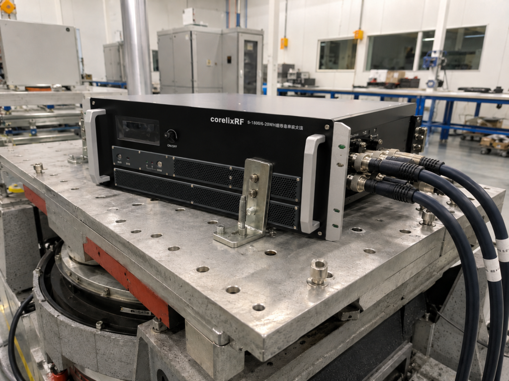
Let me explain: Aircraft engines generate continuous broadband acoustic vibration profiles. These mechanical waves travel through airframes into equipment racks. Coaxial interfaces experience continuous micro-rotational forces from these vibrations. A standard N-Female interface requires precise torque application initially. Flight vibrations slowly back off these threaded locking mechanisms. As threads loosen slightly physical contact pressure drops immediately. Reduced pressure alters characteristic impedance away from fifty ohms. This sudden impedance mismatch reflects power back toward amplifiers. High-power systems pushing 500W cannot tolerate such huge reflections. The CRF-PA-6000M18000M-500W model utilizes WRD650 waveguide output specifically. Waveguide flanges bolted directly resist rotational loosening quite effectively. Engineers must specify vibration-resistant fastening hardware for every installation. Safety wire provides another layer of physical back-off prevention. Ignored physical connections always become catastrophic failure points eventually. We instruct system integrators regarding proper torque values consistently. Loose connectors generate excessive heat leading toward total destruction. Reliable radar systems depend upon solid mechanical connector integration.
Connector Interface Specifications
| Port | Connector Type | Mechanical Benefit |
| RF Input | N-Female | Precision threaded locking |
| RF Output | WRD650 Waveguide | Bolted flange stability |
| Control Interface | RS485 / LAN | Secure data transmission |
4. How Do VSWR Spikes From Loosening Connectors Trigger System Catastrophes?
Reflected power destruction cycles
Consider this fact: A loose connector causes immediate and severe standing waves. Reflected energy travels backward hitting power transistor output stages. Gallium Nitride devices handle significant heat under normal conditions. Reflected power concentrates extreme voltage peaks across semiconductor junctions. These voltage spikes exceed breakdown ratings in milliseconds flat. The radar system drops offline completely without warning operators. CorelixRF designs integrate advanced internal protection circuits for safety. The CRF-PA-6000M18000M-500W features strict over-voltage and VSWR defense mechanisms. A maximum 1.5:1 input VSWR limit ensures stable power transfer. Active monitoring detects reflected spikes and shuts down instantly. System integrators require these fast-acting protection loops for survival. A burnt GaN transistor stops million-dollar flight testing immediately. We measure these parameters rigorously using automated test setups. Professional engineering leaves absolutely nothing toward random chance. High-power B2B applications demand fail-safe logic across all boards. Relying upon lucky environmental conditions invites disaster during deployments.
Table 4: Protection Circuit Thresholds
| Parameter | Limit | System Action |
| Input VSWR | > 1.5:1 | Immediate power attenuation |
| Over-voltage | > Defined limit | Hardware shutdown sequence |
| Spurious Emissions | > -60 dBc | Signal filtering activation |
5. Why Are Rigid Matching Networks Inadequate For Airborne Deployments?
Flexibility requirements within RF paths
What is the real story? Traditional matching networks employ rigid ceramic substrate materials frequently. Ceramic fractures easily when subjected toward bending or twisting. Aircraft wings flex significantly altering internal equipment bay dimensions. These macro-level changes force stress onto rigid internal components. Flexible microwave cables absorb some external chassis deflection successfully. Internal matching components must handle whatever vibration bypasses external mounts. We design our circuits utilizing specialized stress-relieving geometry patterns. Traces feature rounded corners preventing localized stress concentration points. Our thirty years of manufacturing experience dictates these rules. B2B clients demand continuous operation across thousands of hours. Electronic warfare applications tolerate zero downtime during active deployments. The engineering truth reveals itself through long-term survivability metrics. You cannot fake reliability testing regarding airborne high-power modules. System designs failing environmental validation waste significant development budgets. Implementing proper structural logic saves enormous post-deployment maintenance costs. Every RF front-end needs structural integrity from day one.
Operational Tolerances
| Metric | Specification | Engineering Impact |
| Temperature Range | 0 to 50 °C | Defines cooling requirements |
| Gain Flatness | ±6 dB | Requires substrate stability |
| Adjustable Gain | 20 dB | Enables dynamic scaling |
6. What Role Does High-Frequency Material Selection Play Against Vibration?
Substrate durability and dielectric stability
This is where it gets interesting: Selecting proper board material prevents high-frequency performance degradation entirely. Standard glass-reinforced epoxy performs terribly at eighteen gigahertz frequencies. Polytetrafluoroethylene composites provide necessary electrical performance alongside mechanical flexibility. These advanced substrates maintain steady dielectric constants across temperatures. The 6,000 to 18,000 MHz range demands extreme consistency. Any physical warping alters trace impedance causing gain ripples. Our CRF-PA-6000M18000M-500W datasheet specifies a 57 dB gain parameter. Gain flatness remains strictly within six decibels across wideband operation. Maintaining this flatness requires absolute physical stability under vibration. We bond soft substrates onto solid metal carrier plates. This composite construction provides both electrical excellence and rigidity. Aluminum carriers dissipate heat while resisting low-frequency mechanical resonance. This practical approach solves conflicting mechanical and electrical requirements. R&D engineers respect materials performing perfectly under extreme duress. Material science forms the absolute foundation of reliable manufacturing.
7. How Does Broadband Operation Impact Mechanical Design Requirements?
Managing wide frequency range stresses
Listen to this: Covering six to eighteen gigahertz requires intricate component arrangements. Small components manage high frequencies while large ones handle power. This diverse mass distribution creates complex internal resonant frequencies. Vibration testing must sweep from low acoustic up higher. We monitor output spectrum purity during these intense physical tests. Any mechanical resonance manifests as phase noise or spurious signals. The datasheet guarantees spurious emissions strictly below minus sixty decibels. Achieving this requires securing every single wire and inductor. Air cooling paths must not create acoustic whistling effects. Fans must survive continuous operation without bearing failure happening. We select ruggedized cooling solutions specifically meant for aviation. Our internal technical team verifies structural integrity via x-ray. Every manufactured lot undergoes strict physical stress screening procedures. You need guaranteed performance when integrating complex communication systems. Our products deliver engineering truth straight toward your loading dock.
8. What Thermal Dissipation Strategies Survive Airborne Regimes?
Conduction and forced convection interplay
Get this: Heat represents the second greatest enemy for power amplifiers. Generating five hundred watts of RF creates massive thermal waste. Airflow at high altitudes drops in density quite drastically. Thin air removes far less heat per cubic foot. The cooling fins must feature larger surface areas accordingly. We machine heat sinks directly from solid aluminum blocks. Extruded fins break off when subjected toward engine vibration. Solidly machined chassis designs survive aggressive shaking without failing. The CRF-PA-6000M18000M-500W operates safely up till fifty degrees Celsius. Over-temperature protection circuits prevent catastrophic core meltdown events actively. Thermal interface materials must not pump out under vibration. We utilize specialized phase-change pads maintaining perfect thermal contact. Proper engineering ensures reliable communication links regardless of weather. B2B system integrators evaluate these exact thermal dissipation characteristics heavily. Real engineering solves heat issues before they become field failures.
9. How Do Engineers Verify System Level Reliability Prior To Flight?
Pre-flight validation protocols
Truth be told: Nobody mounts unproven hardware onto an active flight platform. Systems undergo massive shaker table testing prior to approval. Engineers run network analyzers monitoring scattering parameters continuously during vibration. A dropping S21 curve indicates an internal connection failing. Increasing S11 readings warn about output connector loosening immediately. We supply test data and pattern files for evaluation. LAN and RS485 interfaces allow remote monitoring during tests. Our software team validates all remote communication protocols thoroughly. B2B international trade requires absolute confidence before shipping crates. Our mainland China factory facility houses advanced environmental chambers. We test extreme cold soaking followed by rapid heating. This simulates a high-altitude aircraft descending into a desert. Physical mechanisms dominate RF performance outcomes eventually every time. Validated hardware acts as a shield against mission failure. CorelixRF guarantees specifications through brutal empirical verification methods.
10. How Should System Integrators Evaluate RF Amplifiers For Aircraft?
Objective procurement criteria
Keep this in mind: Look beyond basic datasheet numbers when selecting flight hardware. Request specific vibration testing methodology documentation from your supplier. Ask about internal potting strategies and connector fastening methods. CorelixRF delivers objective engineering truth regarding every produced unit. We avoid flamboyant marketing rhetoric completely during technical discussions. The CRF-PA-6000M18000M-500W datasheet reflects guaranteed performance under specified conditions. We build RF front-ends focusing entirely upon structural physics. Micro-cracking solder joints ruin multi-million dollar sensor payload missions. Proper mechanical matching prevents these specific catastrophic failure chains. Our four hundred staff members stand behind our manufacturing. Radar and electronic warfare designers trust our factory output. We invite rigorous technical audits of our manufacturing processes. Rely upon solid engineering practice rather than empty promises. Connectors stay tight when brilliant minds engineer the hardware. Choose a factory prioritizing physical reality over digital illusions.
Mechanical resonance destroys standard RF amplifiers during flight operations constantly. Proper structural engineering prevents microscopic solder joint cracking entirely. B2B system integrators require ruggedized GaN technology hardware. Evaluate your airborne front-end specifications using objective reality. Contact our technical personnel regarding the CRF-PA-6000M18000M-500W datasheet today. Protect your next radar mission against catastrophic vibration failures.
FAQ
Q1: What defines structural resonance inside airborne RF amplifiers?
Low-frequency vibration from aircraft engines matches the natural frequency of internal components. This creates violent physical shaking that cracks microscopic solder joints and destroys delicate RF traces.
Q2: How does the CRF-PA-6000M18000M-500W handle thermal dissipation?
The amplifier uses air cooling via a solidly machined aluminum chassis. Built-in over-temperature protection circuits actively monitor the internal GaN components to prevent thermal meltdown up to 50°C.
Q3: Why do standard solder joints crack under vibration?
Standard commercial tin-lead alloys lack the physical flexibility required to survive continuous low-frequency acoustic shaking. They develop micro-cracks that expand through thermal cycling and increase electrical resistance.
Q4: How do VSWR spikes affect Gallium Nitride transistors?
A loose connector reflects high-power RF energy back into the amplifier. This reflected power creates massive voltage spikes that can instantly destroy GaN transistor junctions without active protection.
Q5: What makes WRD650 waveguide superior against mechanical loosening?
Unlike threaded coaxial connectors that can back off under vibration, the WRD650 waveguide output uses bolted flanges. This provides massive physical stability and prevents dangerous impedance mismatches during flight.
Turn this RF requirement into a quotable specification
Use this article as a starting point for a buildable RF specification. Before quoting, CorelixRF normally checks frequency range, output power, gain flatness, duty cycle, load mismatch, thermal path, control interface, enclosure limits and acceptance data.
- rugged RF systems – review ruggedization expectations for vibration, thermal and field maintenance
- RF front-end platform – compare the RF chain as a system instead of selecting one isolated module
- RF power amplifier platforms – match the article topic to available RF power amplifier families
- broadband SDR signal source – connect waveform or signal-source requirements to the RF front-end
- RFQ checklist – send the data buyers usually forget, including band, power, duty cycle, interface and test standard
- delivery documentation – check what documents can support incoming inspection, FAT review and long-term maintenance
- engineering contact – send the application notes, block diagram or target specification to engineering sales
For a faster review, send operating band, power target, modulation or waveform, antenna/load condition, cooling limit, mechanical envelope and target test standard through the RFQ or contact path.