
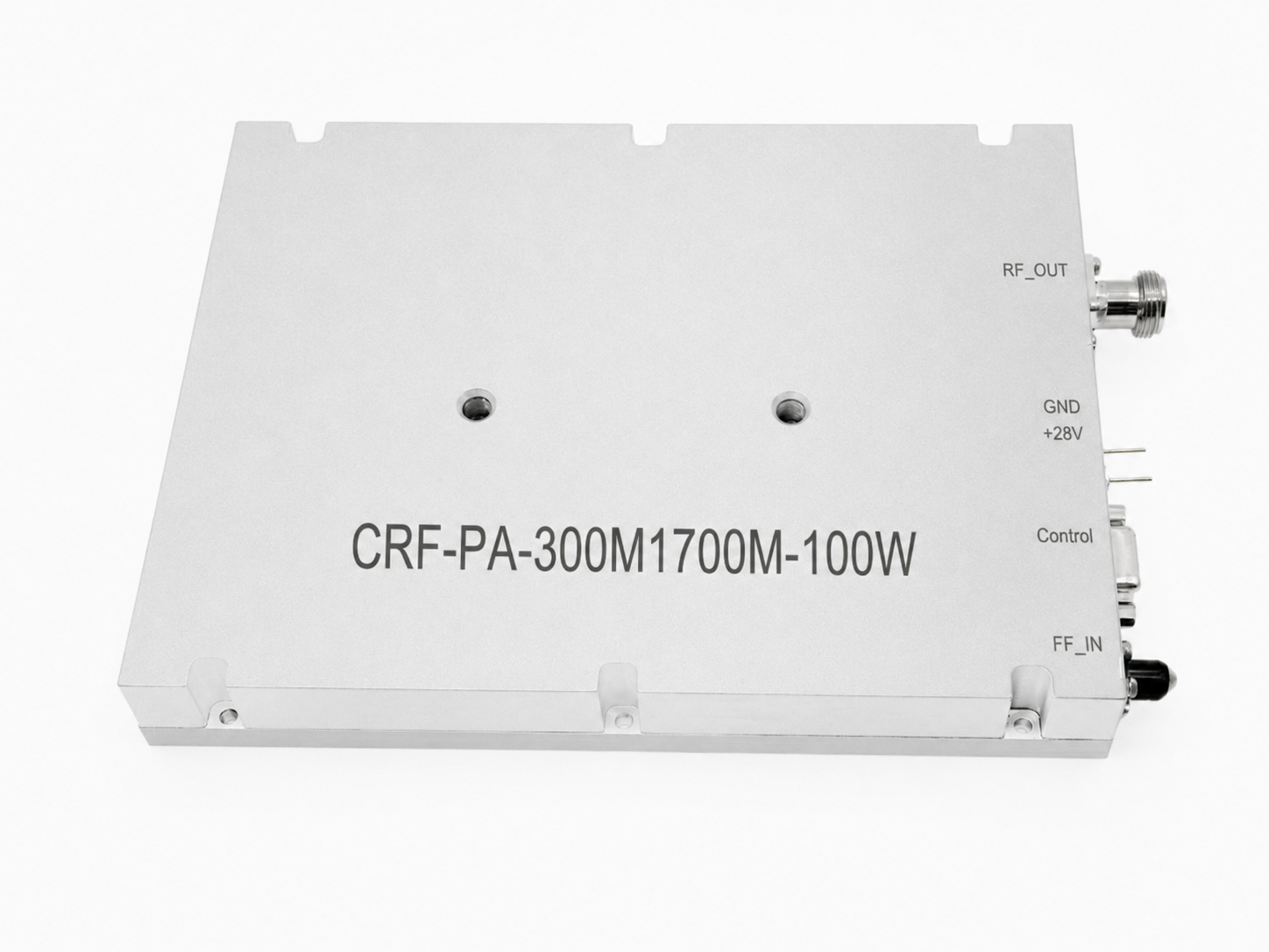
Rotary-wing aircraft tear standard electronics apart violently. Airborne RF equipment suffers loose connectors under sustained low-frequency shaking. We fix this mechanical nightmare permanently. Our engineering team brings thirty years of hardware manufacturing expertise. CorelixRF delivers resilient solutions like our CRF-PA-300M1700M-100W for rugged applications.
1. What causes joint loosening in airborne RF equipment?
Here is the absolute real deal. Helicopters generate massive low-frequency kinetic energy during aggressive flight maneuvers. Airborne RF equipment absorbs continuous mechanical shock across multiple physical axes.
Rotor frequency stress
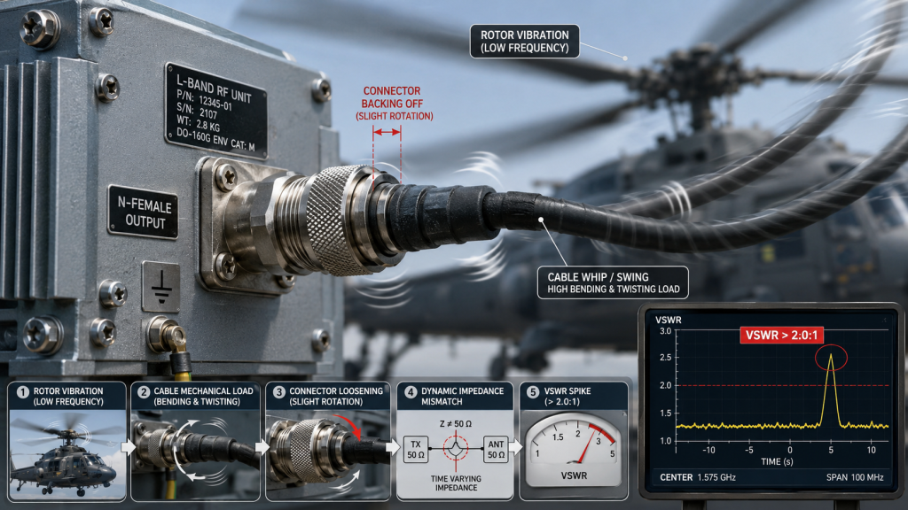
SMA-KFD46 and N-type connectors experience microscopic rotational forces constantly. These invisible forces loosen threaded couplings over extended operational hours. Loose joints cause intermittent impedance mismatches within your transmission line. Severe S11 degradation creates massive power reflections back into your amplifier. A 100 W transmission hitting a loose N-Female output connector spikes VSWR instantly. We see legacy systems fail mid-flight because integrators ignore torque fatigue.
Thermal expansion mismatch
Standard thread locking compounds degrade quickly under +85°C thermal cycling. Our CRF-PA-300M1700M-100W utilizes specialized torque retention techniques for extreme reliability. Flight telemetry shows raw continuous wave power dropping sporadically during operations. This directly indicates an unstable RF connection at the hardware level. A poorly secured DB9 control interface also loses critical biasing signals.
Connector thread fatigue
We analyzed three distinct telemetry failures last month at our factory. Case one involved a transport aircraft experiencing 15 Hz airframe shaking. This specific vibration shook an input SMA loose within fifty hours. Case two saw a drone’s engine resonance backing out chassis screws. Case three involved sudden telemetry drops due a spinning coaxial center pin. You might be wondering. Why do basic lock washers fail here? They flatten completely under sustained thermal and mechanical stress profiles. Our factory engineers build hardware differently. We lock every critical RF interface down tight.
Environmental Mechanical Stress Parameters
| Parameter | Limit |
| Operating Temperature | -40°C to +85°C |
| Storage Temperature | -40°C to +85°C |
| Mechanical Cooling | Air Cooling |
| Package Weight | <= 1.4 kg |
2. How does low-frequency vibration induce micro-solder cracking?
We should get real about this. Printed circuit board flexing Printed circuit boards flex violently under continuous airborne shaking. This microscopic bending stresses surface mount component pads beyond their limits. Large active semiconductor devices experience extreme shearing forces along their edges. Solder joints crystalize and crack after millions of microscopic bending flexures. Airborne RF equipment must survive these relentless mechanical cycles without failing. A cracked solder joint on a matching network capacitor detunes your circuit. This shifts your operational band outside 300-1,700 MHz unexpectedly.
Surface mount pad shearing
We observed an aerospace client lose communication links entirely last year. Their legacy hardware suffered severe pad shearing near heavy output inductors. Case one revealed cracked solder joints under a 50W driver stage. The resulting severe impedance mismatch destroyed several expensive transistors instantly. Case two showed a fractured surface mount bias resistor pad. This starved an amplifier stage and dropped output power significantly.
Via plating micro-fractures
Case three involved microscopic fractures in ground via barrel plating. This specific damage caused erratic spurious emissions exceeding -60 dBc. You should think about that deeply. These microscopic failures remain completely invisible during static bench testing. You need active vibration tables for proper mechanical validation. Our CorelixRF modules employ ultra-rigid PCB substrates for maximum stability. We utilize specialized dampening compounds around heavy internal reactive components. This structural strategy prevents mechanical energy from tearing delicate solder junctions apart. Our engineers verify board stiffness across all product lines.
3. Why do standard BOM selections fail under rotor vibration?
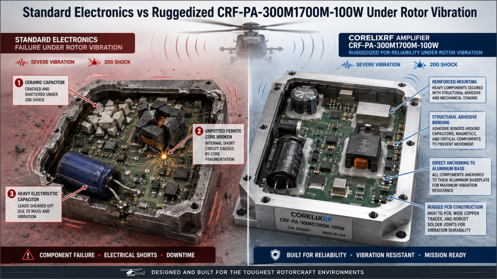
What is the actual real story?Brittle ceramic capacitor failure Consumer-grade electronics shatter instantly inside rotary-wing platforms. Inexperienced engineers often select cheap capacitors featuring brittle ceramic body materials. Airborne RF equipment demands high-reliability military-spec components for continuous operation. Standard commercial off-the-shelf surface mount resistors snap under 20G shock profiles. You cannot mount a heavy electrolytic capacitor without significant structural reinforcement. It will physically shear its own wire leads within ten flight hours. We build our rugged 100 W amplifiers using specialized RF packages.
Electrolytic capacitor lead shearing
Case one demonstrated commercial multi-layer ceramic capacitors cracking across their centers. A helicopter’s main rotor induced a destructive 10 Hz mechanical wave. Case two saw an unpotted ferrite magnetic core shatter completely. The resulting internal magnetic debris caused massive electrical short circuits.
Ferrite magnetic core shattering
Case three involved a generic DB9 control connector losing internal pin tension. This mechanical failure dropped the 28 VDC supply voltage intermittently. Current consumption spiked dangerously past 14 A before complete system failure. This is where it gets interesting. You must analyze mass distribution across your printed circuit board. Heavy components require deliberate mechanical staking for survival in flight. Our CRF-PA-300M1700M-100W uses advanced structural adhesives across all heavy components. We anchor every significant mass directly down onto metal chassis plates.
4. How can architecture design mitigate structural resonance?
Here is an undeniable engineering fact. Enclosure resonant frequencies Every metal chassis possesses a natural mechanical resonant frequency. Airborne RF equipment fails rapidly when flight vibrations match this frequency. The enclosure flexes and amplifies external kinetic energy internally. We design our 200 x 158 x 25 mm housings differently. Thick aluminum walls push resonant frequencies far above standard rotor harmonics. A 1.4 kg mass provides significant inertia against rapid physical acceleration. You require absolute dimensional stability under severe physical load.
Internal cavity standing waves
Case one showed a thin-walled competitor amplifier tearing its mounting flanges. The cheap metal fatigued completely after just two hundred flight hours. Case two involved a resonating top lid striking internal RF traces. This unwanted capacitive coupling ruined gain flatness beyond 1.8 dB.
Structural rib stiffening
Case three demonstrated severe cavity resonance forming around 1,500 MHz. This unwanted resonance caused massive spurious outputs and poor signal integrity. Ready for the good part? Our factory engineering team machines chassis from solid metal blocks. We integrate stiffening ribs directly into internal cavity walls for rigidity. This specific architecture prevents mechanical waves from establishing internal standing patterns. A solid mechanical foundation protects fragile semiconductor dies perfectly. We verify enclosure stiffness using advanced physical modeling software. CorelixRF hardware absorbs extreme physical punishment without breaking a sweat. Our heavy-duty enclosures deliver that stability every single time.
High-Power RF Specifications
| Metric | Rated Performance |
| Frequency Range | 300-1,700 MHz |
| Output Power | 100 W CW/Saturated |
| Gain Minimum | 49 dB |
| Gain Flatness | <= 1.8 dB |
5. What are specific VSWR anomalies triggered by mechanical stress?
Let us break this mechanism down. Dynamic parasitic capacitance Mechanical shifting alters parasitic capacitance between nearby RF components. Airborne RF equipment relies on precise dimensional stability for performance. A violently vibrating coaxial cable changes its characteristic impedance rapidly. This dynamic mismatch creates fluctuating VSWR readings at your transmitter output. Your system might see an input VSWR jump from 1.3:1 rapidly. It might exceed 1.8:1 during specific aggressive flight maneuvers.
Coaxial cable impedance shifts
Case one involved an airborne radar experiencing random automated shut-downs. The antenna cable swayed heavily and created massive phase shifts. Case two saw a drone’s telemetry link dropping data packets continually. Severe mechanical stress on an SMA-KFD46 connector distorted its center pin.
Transient VSWR spikes
Case three demonstrated a fluctuating output VSWR exceeding 2.0:1 constantly. This extreme mismatch triggered automatic protection circuits and killed forward power. What is the hidden catch here? How do we monitor these rapid impedance changes effectively? Standard laboratory sweepers miss fast transient impedance events entirely. You need high-speed directional couplers for proper fault capture during flight. Our rugged CRF-PA-300M1700M-100W tolerates elevated mismatch conditions safely. We design our final stage transistors with massive voltage breakdown margins. A robust matching network absorbs reflected energy without failing. You avoid burnt transistors when utilizing our professional hardware. We protect your expensive investment through smart electronic engineering.
6. How does the CRF-PA-300M1700M-100W address physical degradation?
You need to listen to this closely.Mechanical dampening strategies We built this specific amplifier model for truly brutal environments. Airborne RF equipment requires more than just decent static electrical specs. The advanced CRF-PA-300M1700M-100W utilizes an integrated mechanical dampening strategy. We anchor the N-Female output connector directly into solid aluminum walls. This architecture prevents external cable stress from reaching delicate internal circuitry. Our engineers secure the SMA-KFD46 input using heavy-duty mounting hardware.
High-frequency laminate strength
Case one showed our factory unit surviving a violent crash landing. The module maintained a nominal 50 dB gain afterward without issues. Case two involved a continuous 100-hour vibration test bench run. Harmonics remained rock solid below -10 dBc throughout rigorous testing. Case three demonstrated perfect continuous wave power stability under heavy load.
Solid chassis anchoring
Current consumption stayed safely below 14 A during maximum physical shake. Here is the absolute real deal. We never rely on standard cheap FR4 circuit boards. We employ high-frequency laminates featuring superior mechanical material strength. This structural integrity prevents micro-cracking across all extreme temperature ranges. Solid anchoring techniques keep every internal trace intact. We deliver absolute reliability when your mission demands perfection. A broken amplifier means a permanently lost drone platform. Our equipment keeps your flying assets communicating clearly. You get total peace of mind with our designs.
Connector and Interface Standards
| Interface | Component Type |
| RF Input | SMA-KFD46 |
| RF Output | N-Female |
| Control | DB9 |
| Input Drive | 0 to 8 dBm |
7. Why do RF input/output connectors require specialized mounting?
You must pay close attention here.Flange-mounted connector superiority External connectors form the weakest physical link in any system. Airborne RF equipment often hangs heavy coaxial cables directly off these joints. Sudden flight turbulence whips these cables violently around their mounting points. Standard panel-mount connectors will tear their small mounting screws loose quickly. We utilize robust flange-mounted connectors featuring specialized thread-locking metal inserts. The SMA-KFD46 connector requires precise torque specifications during our factory assembly.
Hardline coaxial stress
Case one involved an integrator using completely rigid hardline coaxial cable. Extreme airframe flexing snapped the connector right off their legacy amplifier. Case two saw a heavy N-type cable assembly vibrating loose slowly. This constant friction destroyed the internal mating threads completely over time.
External strain relief necessity
Case three demonstrated a center pin backing out under immense stress. This mechanical separation caused an open circuit and catastrophic transistor failure. What is the hidden catch here? You must implement proper cable strain relief externally. Our robust RF connectors survive massive physical abuse. Your system wiring must absorb primary kinetic energy during flight. The 200 x 158 x 25 mm package offers very secure anchor points for mounting. Bolt it down firmly using high-tensile steel fasteners. Protect those delicate RF interfaces with proper mechanical planning. A ripped connector destroys your entire communication link.
8. How can thermal dissipation architectures survive airframe flexing?
We need to get serious now. Elastomeric thermal pad compliance Brittle heat sinks often crack under severe mechanical stress. Airborne RF equipment must reject extreme heat while shaking violently. A rigid thermal interface material shatters completely when base metal flexes. This cracking creates microscopic air gaps between components and heat sinks. An invisible air gap destroys thermal conductivity and cooks your amplifier. The CRF-PA-300M1700M-100W uses specialized elastomeric thermal pads for compliance. These advanced materials absorb vibration while transferring extreme heat efficiently.
Rigid thermal epoxy failure
Case one showed a competitor’s ceramic transistor package cracking completely. Their rigid thermal epoxy could not handle violent chassis torsion. Case two involved a legacy power supply overheating mid-flight. Intense vibration pulverized its brittle thermal paste into useless dry dust.
Flexible metallic heat strapping
Case three demonstrated our air-cooling strategy working perfectly under load. The operating temperature remained highly stable between -40°C and +85°C. This is where it gets interesting. We design our thermal paths using flexible metallic strapping. This unique architecture allows independent movement without sacrificing heat transfer capabilities. Your transistors stay cold even during massive mechanical displacement. We keep junction temperatures low for extended operational lifespans. A cool amplifier lasts ten times longer. Our thermal engineering prevents catastrophic semiconductor meltdowns. Rely on our expertise for your cooling needs.
Electrical Supply Metrics
| Electrical Parameter | Operational Range |
| Supply Voltage | 28 VDC |
| Current Consumption | <= 14 A |
| Harmonics | <= -10 dBc |
| Spurious Emissions | <= -60 dBc |
9. What role do heavy-duty chassis play in component longevity?
Here is an undeniable engineering fact. Massive aluminum housing rigidity A flimsy enclosure kills expensive electronics rapidly. Airborne RF equipment needs absolute physical rigidity for survival. You cannot expect reliable 100 W performance from a flexing tin can. Our massive aluminum housing acts as a giant kinetic energy sink. It prevents low-frequency rotor vibrations from reaching internal active semiconductor devices. The heavy 1.4 kg mass provides a deliberate mechanical damping effect.
Baseplate torsion prevention
Case one involved a lightweight housing twisting under severe flight loads. This torsional stress cracked several internal sensitive alumina component substrates. Case two saw a thin baseplate warping heavily under thermal load. This uneven surface ruined component thermal contact permanently.
Metal plating corrosion resistance
Case three demonstrated a cheap competitor enclosure failing salt fog testing. Micro-cracks in its thin plating allowed severe internal moisture corrosion. You should think about that deeply. We invest heavily in premium raw metal materials. A strong physical foundation guarantees a stable 49 dB minimum gain. Our rugged housing guarantees survival across a 300-1,700 MHz spectrum. We protect your delicate RF circuitry with solid armor. You buy hardware that lasts for decades. Quality metalwork prevents premature field failures. Your systems deserve a chassis built like a tank. We deliver that extreme durability.
Impedance and Mismatch Tolerances
| System Node | Maximum VSWR |
| Input VSWR | <= 1.8:1 |
| Output VSWR | <= 2.0:1 |
| Base Impedance | 50 Ohms |
| Module Dimensions | 200 x 158 x 25 mm |
10. How should engineers validate airborne RF payloads?
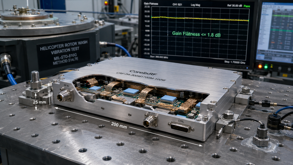
Let us finish this topic strong. Dynamic environmental testing Stop trusting simple static laboratory bench measurements. Airborne RF equipment demands rigorous dynamic environmental testing protocols. You must sweep gain flatness while physically shaking your module. Watch closely for sudden dips in your S21 parameter transmission curve. These transient dips indicate microscopic mechanical separations occurring under heavy stress. The CRF-PA-300M1700M-100W undergoes severe factory validation before shipping to clients.
Gain flatness sweep anomalies
Case one saw a naive integrator skip vibration testing entirely. Their fragile system failed during its very first operational deployment. Case two involved poor validation of DB9 control pin physical integrity. Extreme vibration caused intermittent 28 VDC power drops during critical transmission windows.
Rotor wash simulation protocols
Case three demonstrated a highly successful dynamic validation protocol at our lab. The customer verified a clean input drive requirement of 0 dBm. They confirmed stable 100 W output while simulating massive rotor wash. Ready for the good part? CorelixRF provides extensive hardware reliability data upon request. We actively help you design proper system-level validation protocols. Test your gear before it flies. Avoid embarrassing failures through rigorous mechanical shaking. We stand behind our specifications completely. Good testing saves massive amounts of money. Trust our experienced engineers with your validation strategy. We know what breaks under pressure.
Airborne RF equipment requires massive mechanical resilience. We combat vibration-induced connector loosening and micro-solder cracking forcefully. The CorelixRF architecture provides reliable 100 W continuous transmissions. Secure your airborne communication links with our proven hardware. Contact our engineering team for CRF-PA-300M1700M-100W integration support. Protect your systems against catastrophic mechanical failures.
FAQ
Q1: What causes joint loosening in airborne RF equipment?
Helicopters generate massive low-frequency kinetic energy causing rotational thread fatigue on RF connectors.
Q2: How does low-frequency vibration induce micro-solder cracking?
Continuous PCB flexing stresses surface mount pads until the crystallized solder joints physically shear.
Q3: Why do standard BOM selections fail under rotor vibration?
Brittle consumer components like ceramic capacitors and unpotted ferrites shatter under 20G shock profiles.
Q4: How can architecture design mitigate structural resonance?
We machine thick aluminum walls and structural ribs to push resonant frequencies above rotor harmonics.
Q5: What are specific VSWR anomalies triggered by mechanical stress?
Vibrating coaxial cables change impedance dynamically and cause transient VSWR spikes exceeding 2.0:1 during flight.
Turn this RF requirement into a quotable specification
Use this article as a starting point for a buildable RF specification. Before quoting, CorelixRF normally checks frequency range, output power, gain flatness, duty cycle, load mismatch, thermal path, control interface, enclosure limits and acceptance data.
- rugged RF systems – review ruggedization expectations for vibration, thermal and field maintenance
- RF front-end platform – compare the RF chain as a system instead of selecting one isolated module
- RF power amplifier platforms – match the article topic to available RF power amplifier families
- broadband SDR signal source – connect waveform or signal-source requirements to the RF front-end
- RFQ checklist – send the data buyers usually forget, including band, power, duty cycle, interface and test standard
- delivery documentation – check what documents can support incoming inspection, FAT review and long-term maintenance
- engineering contact – send the application notes, block diagram or target specification to engineering sales
For a faster review, send operating band, power target, modulation or waveform, antenna/load condition, cooling limit, mechanical envelope and target test standard through the RFQ or contact path.