
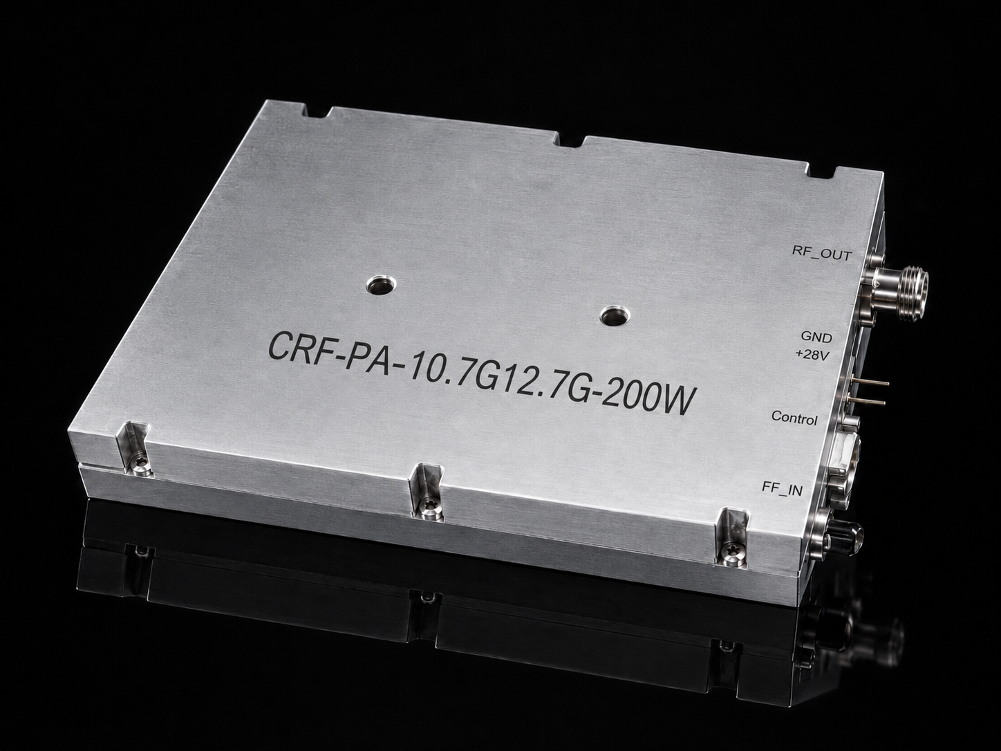
Diagnosing Airborne RF Signal Anomalies In Field. Airborne platforms expose hardware to brutal mechanical realities. Radar screens flash VSWR warnings during heavy turbulence unexpectedly. Continuous mechanical stress ruins airborne equipment signal integrity fast. CorelixRF leverages thirty years of strict manufacturing expertise. We deliver ruggedized RF power amplifiers for industry. Our solutions eliminate microscopic joint cracking failures entirely.
1. Why Do Airborne RF Signals Experience Sudden Drops?
Mechanical Stress Transfer
Airborne platforms endure extreme mechanical environments constantly. Helicopters generate sustained low-frequency vibrations during normal flight operations. Fixed-wing aircraft face high-G maneuvers within combat training scenarios. Unmanned aerial vehicles encounter violent wind shear forces aloft. Here is the deal. These physical forces transfer directly into rigid waveguide assemblies. WR75 flanges absorb tremendous shear stress over time. SMA connectors slowly back out under constant chattering. RF engineers often observe abrupt power loss on consoles. A radar system might drop output power unexpectedly mid-flight. Communication links suffer intermittent packet loss during banking maneuvers. Electronic warfare jammers lose target tracking capabilities at high speeds. Every loose thread increases insertion loss significantly across a circuit. Field technicians find perfectly intact cables visually upon inspection. Hidden mechanical degradation causes severe RF reflections internally. Transmitter energy bounces back into a final amplification stage. This reflected power generates massive heat localized at a connector. Thermal runaway destroys delicate Gallium Nitride transistors quickly. System integrators must understand these physical mechanisms deeply.
2. How Does Continuous Vibration Affect Microscopic Solder Joints?
Thermal-Mechanical Fatigue
Solder joints look solid under normal visual inspection. What’s the real story? Microscopic fatigue accumulates over thousands of active flight hours. Airborne equipment signal anomalies begin at a PCB level. Gallium Nitride transistors generate massive thermal loads operating continuously. Heating causes circuit substrates to expand rapidly. Cooling contracts materials during high-altitude cold weather operations. Low-frequency oscillation compounds this regular thermal cycling heavily. A crystalline structure of tin-lead alloy breaks down slowly. Micro-cracks propagate through via connections without any warning. One field incident involved a Ku-band data link drone. An amplifier showed nominal gain on a laboratory bench. It failed entirely during engine run-up tarmac tests. Another case featured a gimbaled payload system. Video transmission glitched specifically at 3000 RPM engine speed. A third failure happened in phased array radar testing. Solder fractures detached a coupling capacitor from its pad. These micro-cracks act like tiny variable attenuators changing resistance. Signal integrity degrades before complete hardware failure occurs.
Failure Modes Analysis
| Failure Mode | Root Cause | Observable Symptom |
| SMA Back-out | Vibration | Intermittent signal loss |
| Flange Gap | Torque decay | Sudden VSWR spike |
| Solder Crack | Thermal cycling | Gradual gain degradation |
3. What Are Field Symptoms Of Loosening Connectors?
Instrumentation Signatures
Diagnosing these faults requires specific microwave instrumentation. You cannot rely on built-in software test algorithms alone. This is where it gets interesting. Airborne equipment signal anomalies manifest uniquely on test gear. A Vector Network Analyzer shows severe high-frequency roll-off. An S21 curve collapses completely above 12 GHz. Spectrum analyzers display bizarre noise floor elevations unexpectedly. Broadband noise increases when ground contacts lose mating pressure. One avionics team noticed random phase shifts during operation. Their phased array antenna lost electrical steering accuracy completely. Another flight crew recorded sudden intermodulation distortion spikes. A loose WR75 joint acted like an unintended diode. A third maintenance group saw return loss degrade slowly. An S11 parameter drifted from -20dB towards -5dB gradually. These symptoms point directly toward mechanical integrity loss. RF engineers must recognize these specific equipment signatures immediately. Replacing components randomly wastes valuable maintenance turnaround time. Objective measurement data exposes physical hardware flaws reliably.
4. How Can Engineers Troubleshoot Airborne Equipment On Tarmac?
Tarmac Diagnostic Tactics
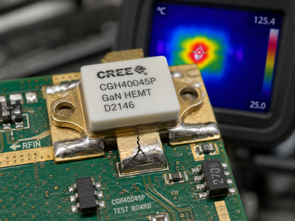
Tarmac conditions offer terrible troubleshooting environments for technicians. Crews face deafening engine noise alongside harsh weather. Standard laboratory procedures fail completely under these conditions. Ready for the good part? Portable VSWR meters provide immediate reflection data outdoors. Connect a directional coupler before your antenna feed. Monitor forward and reverse power during engine spool-up phases. Sudden reverse power spikes indicate mechanical separation instantly. Use a portable oscilloscope monitoring DC current draw. An amplifier drawing fluctuating current implies unstable RF drive. One maintenance team found a loose input coaxial cable. They tapped a chassis with a plastic screwdriver handle. DC current draw jumped erratically during physical tapping. Another field engineer used a handheld spectrum analyzer. They detected excessive harmonics radiating from a waveguide flange. A third case involved thermal imaging cameras inspecting bays. A loose connector showed excessive localized heating immediately. These hardcore field tactics isolate faults extremely fast.
Troubleshooting Equipment Matrix
| Tool Type | Target Metric | Diagnosis Goal |
| VSWR Meter | Return Loss | Antenna feed mismatch |
| Oscilloscope | DC Ripple | Power supply instability |
| Thermal Imager | Surface Temp | Resistive connection loss |
5. Why Do Commercial Amplifiers Fail In Airborne Environments?
COTS Hardware Limitations
Commercial off-the-shelf amplifiers utilize standard manufacturing processes exclusively. They work perfectly inside stationary air-conditioned server racks. Airborne equipment signal anomalies destroy these commercial units rapidly. You might be wondering. Standard aluminum enclosures flex under operational aerodynamic stress. Commercial printed circuit boards lack rigid conformal coating. Unsupported heavy components snap off during extreme turbulence. A standard block upconverter failed on a patrol aircraft. An internal power supply inductor broke its solder mounts. Another commercial amplifier died inside a wing pod. Salt fog penetrated unsealed chassis seams very quickly. A third unit suffered catastrophic RF transistor failure. A base chassis warped slightly on a mounting plate. Warpage eliminated flat contact with an external heatsink. Industrial reliability requires strict mechanical architecture built purposefully. CorelixRF engineers design housings from solid milled metal blocks. We understand severe environment physics deeply and objectively. Surviving flight demands mass stabilization and hermetic sealing.
6. How Does CRF-PA-10.7G12.7G-200W Solve Vibration Issues?
Ruggedized Architectural Design
We built model CRF-PA-10.7G12.7G-200W for brutal reality. This 10.7-12.7 GHz amplifier delivers 200W reliably. Let me show you. An input utilizes a high-reliability SMA-Female threaded connector. We secure a WR75 output with reinforced mounting points. Internal GaN transistors sit on stress-relieved copper carriers. An entire 28V DC power section features solid potting. We implemented ultra-fast VSWR protection circuitry acting instantly. An RS485 interface reports internal diagnostics directly backwards. One defense integrator deployed this specific model successfully. They experienced zero hardware failures over 500 flight hours. A communication relay drone uses this amplifier currently. Hardware withstands constant 5G maneuvering without output degradation. A radar manufacturer replaced a failing competitor unit recently. Model CRF-PA-10.7G12.7G-200W stabilized their entire system architecture completely. Engineering truth dictates physical ruggedness above all other metrics. We machine every tolerance tightly eliminating resonant frequencies.
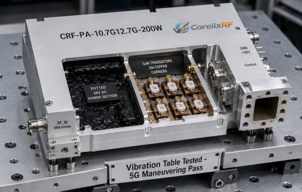
CRF-PA-10.7G12.7G-200W Specifications
| Parameter | Value | Condition |
| Frequency | 10.7 – 12.7 GHz | Operating band |
| Output Power | 200W | CW/Pulsed mode |
| Interface | SMA / WR75 | Milled chassis |
7. What Are Long-Term Reliability Metrics For Airborne RF Power?
Empirical Hardware Qualification
Airborne system integrators demand provable component longevity daily. Factory test data must match field reality exactly. Think about it. CorelixRF follows strict GJB 9001C quality frameworks. We subject every amplifier built toward intense screening. Burn-in testing eliminates early infant mortality hardware failures. Thermal vacuum chambers simulate high-altitude environments perfectly here. Vibration tables replicate exact helicopter rotor acoustic frequencies. Our 400 staff members guarantee absolute consistency across batches. One major client required a 10,000-hour MTBF calculation. We provided detailed component-level thermal stress analysis documents. Another international customer audited our China manufacturing facility. They verified our strict torque-control assembly procedures personally. A third partner tested our units until physical destruction. An amplifier survived thirty percent beyond its rated limits. True engineering relies on empirical data rather than guesses. We document every S-parameter curve before final shipping.
8. How Do Engineers Integrate CRF-PA-10.7G12.7G-200W Properly?
Field Integration Protocols
Proper integration prevents future airborne equipment signal anomalies. Buying rugged hardware solves only half your problem. The truth is. System engineers must design rigid mounting brackets correctly. Use stainless locking wire on all external flange bolts. Apply specified torque values strictly touching every SMA connection. Guarantee an air cooling path remains completely unobstructed always. One integration team ignored thermal interface materials completely. Their amplifier overheated during prolonged ground testing cycles. Another group used cheap flexible coaxial cables internally. Those cables degraded under constant internal wind buffeting. A skilled radar team followed our guidelines exactly. They achieved perfect phase stability across all flight profiles. CorelixRF provides complete mechanical outlines assisting your reference. We supply detailed test data supporting project reviews. Technical personnel verify your specific system architecture continuously. Proper physical installation guarantees maximum radio frequency performance.
Integration Verification Checklist
| Step | Action Required | Verification Method |
| 1 | Torque SMA input | Calibrated torque wrench |
| 2 | Secure WR75 output | Safety locking wire |
| 3 | Verify thermal path | Airflow velocity meter |
9. Why Does CorelixRF Emphasize Engineering Truth In B2B Manufacturing?
Objective Industrial Philosophy
Marketing rhetoric fails immediately on a harsh flightline. Physics dictates actual success of any RF deployment. Here is the kicker. We reject superficial performance claims completely in business. Our factory builds RF power amplifiers based on physics. A thirty-year history proves our manufacturing methodology works. We focus heavily upon insertion loss and thermal resistance. We analyze electron mobility within GaN structures constantly. One competitor promised impossible DC efficiency numbers previously. Their field units burned out during summer operations. Another supplier faked their mechanical vibration test reports. Our engineers exposed that flaw using basic physics math. A major aerospace contractor trusts our objective specifications. They know our datasheets represent actual measured hardware reality. We speak directly with system integrators as peers. Honesty saves engineering teams countless hours resolving anomalies. Industrial hardware requires transparent specifications driving reliable system designs.
10. How Can You Secure Airborne RF Systems Today?
Proactive System Hardening
Airborne equipment signal anomalies threaten mission success daily. Microscopic solder joint cracking remains a silent system killer. Look at the facts. Connectors will loosen without proper mechanical housing design. Model CRF-PA-10.7G12.7G-200W provides a permanent hardware solution immediately. We combined heavy-duty machining utilizing advanced semiconductor tech. This amplifier handles Ku-band atmospheric challenges effortlessly every flight. One customer secured a massive defense contract recently. Our reliable hardware formed their core system backbone. Another integrator reduced their annual maintenance costs significantly. A drone manufacturer eliminated their video drop-out issues entirely. Do not let basic mechanical failures ruin your project. Contact our factory engineering team discussing your specific requirements. We will analyze your link budget objectively today. Let us solve your airborne vibration problems permanently.
Airborne equipment signal anomalies stem from severe mechanical realities. Constant low-frequency vibration destroys weak electrical connections quickly. CorelixRF builds strictly ruggedized RF hardware addressing these faults. Model CRF-PA-10.7G12.7G-200W solves integration failures permanently for engineers. Secure your system architecture utilizing true engineering data. Contact our technical team scheduling detailed project reviews.
FAQ Section
Q1: What are airborne equipment signal anomalies?
Airborne equipment signal anomalies represent unexpected RF performance degradation occurring specifically during flight operations. They manifest as sudden power drops, phase shifts, or elevated noise floors caused by mechanical stress on electronic components.
Q2: How does low-frequency vibration affect solder joints?
Low-frequency vibration compounds thermal stress, causing the crystalline structure of tin-lead or lead-free alloys to fracture. These micro-cracks propagate slowly through PCB vias, acting as variable attenuators that degrade signal integrity over time.
Q3: What are field symptoms of loosening connectors?
Loosening connectors present distinct signatures on test equipment. Engineers will observe high-frequency roll-off on a Vector Network Analyzer, sudden VSWR spikes during engine run-ups, and broadband noise elevation on a spectrum analyzer.
Q4: How does the CRF-PA-10.7G12.7G-200W solve vibration issues?
This amplifier utilizes a milled solid metal chassis, stress-relieved GaN component carriers, and fully potted DC power sections. It secures RF paths using threaded SMA-Female inputs and reinforced WR75 waveguide outputs to resist sheer forces.
Q5: How can engineers troubleshoot airborne equipment on the tarmac?
Engineers should utilize portable VSWR meters with directional couplers to monitor reverse power during engine spool-ups. Monitoring DC current draw with an oscilloscope while applying physical tapping can also isolate loose internal connections quickly.
Turn this RF requirement into a quotable specification
Use this article as a starting point for a buildable RF specification. Before quoting, CorelixRF normally checks frequency range, output power, gain flatness, duty cycle, load mismatch, thermal path, control interface, enclosure limits and acceptance data.
- rugged RF systems – review ruggedization expectations for vibration, thermal and field maintenance
- RF front-end platform – compare the RF chain as a system instead of selecting one isolated module
- RF power amplifier platforms – match the article topic to available RF power amplifier families
- broadband SDR signal source – connect waveform or signal-source requirements to the RF front-end
- RFQ checklist – send the data buyers usually forget, including band, power, duty cycle, interface and test standard
- delivery documentation – check what documents can support incoming inspection, FAT review and long-term maintenance
- engineering contact – send the application notes, block diagram or target specification to engineering sales
For a faster review, send operating band, power target, modulation or waveform, antenna/load condition, cooling limit, mechanical envelope and target test standard through the RFQ or contact path.