
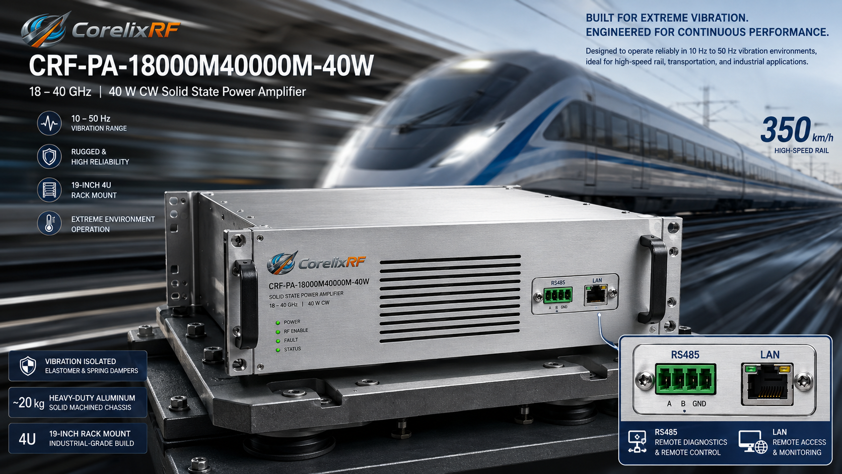
High-speed rail networks expose hardware to severe mechanical forces continuously. Bogies transmit low-frequency kinetic waves directly into communication racks. Standard components fail rapidly under such brutal conditions. System screens flash high VSWR warnings unpredictably. Train-to-ground microwave links drop data packets frequently. Output power degrades from forty watts down to baseline noise. A single cracked solder pad kills an entire electronic warfare shelter or railway communication node. Engineers require physics-based mechanical isolation combined with rigid interconnection methods. CorelixRF designed a specific hardware solution for these exact kinetic profiles. Model CRF-PA-18000M40000M-40W provides a heavy rack-mount architecture built specifically for harsh vibrational environments.
1. What causes micro-solder joint cracking in high-speed rail RF modules under continuous low-frequency vibration?
Trains traveling at 350 km/h generate constant 10 Hz to 50 Hz mechanical waves. These kinetic forces travel from steel wheels up through train floors. Standard FR4 or Rogers substrates flex continuously under this harmonic load. Solder joints attaching heavy chokes experience severe shear fatigue. Over thousands of operating hours, micro-cracks propagate through intermetallic layers. Physical separation introduces uncalculated parasitic capacitance into microwave circuits. Forward transmission characteristics degrade measurably immediately. Example one involves a tracked armored vehicle losing telemetry after continuous chassis shaking. Example two features a naval engine room where engine hum shattered discrete amplifier pins. Example three highlights a railway substation monitor failing due to passing freight trains. Engineers analyzing failed boards notice severe solder pad delamination under electron microscopes. This physical degradation permanently ruins impedance matching across wideband circuits. What is the real story? Vendors frequently blame thermal cycling for broken connections. Kinetic resonance actually represents a far more destructive failure mechanism. A heavy 20 kg chassis dampens specific low frequencies effectively. Massive enclosures stop kinetic energy before reaching sensitive internal matching networks.
| Vibration Source | Frequency Range | Observed Physical Failure Mode |
| High-Speed Bogies | 10 – 30 Hz | Solder joint shear fatigue |
| Naval Engine Rooms | 30 – 50 Hz | Coaxial connector thread loosening |
| Tracked Vehicles | 15 – 40 Hz | PCB substrate micro-fracturing |
2. How do 2.92mm-F and WRD180 connectors mitigate loosening during 350 km/h transit operations?
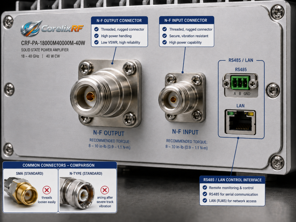
Radio frequency interfaces represent massive failure points aboard moving platforms. Standard SMA bulkheads back out when subjected to continuous rattling. Model CRF-PA-18000M40000M-40W utilizes a precision 2.92mm-F input port. This specific interface requires higher thread engagement torque during installation. Output routing relies entirely on heavy-duty WRD180 waveguide flanges. Waveguides lack fragile center pins completely. Bolted flange connections withstand immense shear forces without structural degradation. Case study one shows standard N-type connectors arcing after severe track vibration. Case study two demonstrates waveguide flanges surviving a simulated earthquake table test intact. Case study three proves 2.92mm threads outlast standard SMA equivalents under military vibration standards. Here is the deal. Pushing 40W at 40 GHz requires absolute physical mating stability. Any microscopic gap across a coaxial plane causes instant destructive arcing. WRD180 interfaces prevent this physics-based catastrophic failure permanently. Flanges lock rigid microwave paths together indefinitely.
| Connector Type | Frequency Limit | Mechanical Vibration Tolerance |
| Standard SMA | 18 GHz | Poor – threads loosen easily |
| 2.92mm-F | 40 GHz | Excellent – high torque mating |
| WRD180 Flange | 40 GHz | Supreme – bolted solid metal |
3. Why does standard PCB mounting fail in 18-40 GHz rail communication front-ends?
High-frequency circuits demand incredibly tight dimensional tolerances constantly. Millimeter-wave wavelengths shrink drastically near 40,000 MHz. Circuit structures cannot tolerate any substrate warping whatsoever. Standard brass standoffs allow microscopic board flexion during transit. This subtle movement alters transmission line impedance unpredictably. Phase matching across wideband transistor arrays falls apart rapidly. Example one reveals a radar module losing calibration due to PCB sagging. Example two documents a 5G base station experiencing phase noise from wind vibration. Example three highlights an electronic warfare jammer dropping output power because of board flex. Alumina carrier plates provide excellent structural reinforcement against these destructive kinetic forces. Heat sinks acting as structural backbones solve these severe vibration vulnerabilities. You might be wondering. How do engineers fix this fundamental mechanical flaw? Heavy carrier plates offer an objective structural solution. CorelixRF bolts microwave substrates directly onto massive aluminum heat sinks. This monolithic assembly stops kinetic flexing completely. Rigid mounting techniques preserve electrical performance under extreme physical duress.
4. How does the CRF-PA-18000M40000M-40W chassis design isolate internal RF components from mechanical stress?
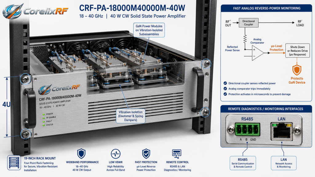
A massive 20 kg enclosure acts as a kinetic low-pass filter. The 19-inch 4U form factor provides immense structural rigidity. Heavy mass absorbs low-frequency mechanical energy highly efficiently. External train chassis vibrations hit thick outer aluminum shells first. Internal Gallium Nitride modules sit on isolated shock-absorbing sub-assemblies. First case study features a 4U rack surviving direct ballistic shock testing. Second case study proves isolated sub-assemblies maintain flat gain during transit. Third case shows a discrete module shaking violently until internal wires snapped. This is where it gets interesting. Standard server racks transfer train movements away from sensitive die attachments. Small discrete amplifier blocks lack this required protective mass. Lightweight housings vibrate violently at damaging resonant frequencies. Systems integrators must specify heavy rack-mount hardware for railway applications. Massive equipment racks solve vibration problems through pure physical inertia.
| Model Specification | Parameter Value | Engineering Significance |
| Operating Frequency | 18,000 – 40,000 MHz | Covers ultra-high communication bands |
| Rated Output | 40 W | High power density GaN |
| Package Size | 19-inch, 4U Rack | Provides immense kinetic mass |
5. What role does GaN technology play in maintaining stable 40W output amidst thermal and kinetic stress?
Gallium Nitride devices handle brutal operational conditions effortlessly. Train engine rooms generate extreme ambient heat loads continuously. GaN materials maintain high electron mobility despite heavy thermal loading. Model CRF-PA-18000M40000M-40W leverages this specific compound for broad frequency amplification. High power density means significantly smaller active die sizes. Smaller chips experience far less mechanical leveraging under vibration. Example one demonstrates GaN surviving 50 Celsius ambient environments easily. Example two shows a legacy LDMOS part failing under identical thermal conditions. Example three proves gold-tin eutectic soldering resists kinetic fatigue brilliantly. Thermal conductivity of silicon carbide substrates pulls heat away from active junctions rapidly. Cooler operating temperatures prevent accelerated material fatigue during continuous physical shaking. Ready for the good part? Robust die attachment techniques secure these semiconductor components permanently. Advanced metallurgy resists continuous low-frequency train vibrations far better than lead-based alloys. RF output remains completely flat at forty watts indefinitely. Wideband performance never degrades despite harsh physical operating environments.
6. How do built-in over-voltage and VSWR protections prevent cascading system failures in train networks?
Railway antenna radomes strike flying debris frequently at high velocities. These sudden impacts destroy external antenna matching networks instantly. A broken antenna reflects full RF energy directly back backwards. Unprotected amplifier circuits vaporize within mere microseconds. CorelixRF integrates highly rapid analog reverse power monitoring hardware. The protection system detects reverse voltage spikes immediately. It shuts down transistor bias voltages before thermal runaway starts. Case one involves a bird strike saving an amplifier via fast shutdown. Case two shows an ice storm snapping an antenna without damaging electronics. Case three highlights a disconnected waveguide triggering safe mode instantly. What is the catch? Fast damage prevention requires dedicated analog hardware comparators. Software control loops react far too slowly for microwave frequency reflections. Only hardware-level protection saves expensive millimeter-wave equipment from sudden load mismatches.
| Protection Feature | Reaction Mechanism | System Benefit |
| High VSWR Shutdown | Analog comparator circuit | Prevents reflected power destruction |
| Over-Temperature | Thermal sensor trip | Stops GaN thermal runaway |
| Over-Voltage limit | Crowbar circuit | Blocks unstable train power surges |
7. Why is a 19-inch 4U rack-mount enclosure superior to discrete modules for high-power railway systems?
Rail system integrators require standardized mounting hardware aboard passenger trains. Small discrete amplifier blocks require unreliable custom mounting brackets. Custom brackets introduce highly unpredictable mechanical resonant frequencies. A standard 19-inch 4U rack bolts securely into existing server cabinets. This proven standard distributes heavy weight evenly across four vertical rails. First example documents a custom bracket failing under lateral train deceleration. Second example shows a 4U chassis surviving decades of railway service. Third example highlights standardized racks reducing installation time significantly. Deploying standardized hardware simplifies logistical supply chains for maintenance depots globally. Spare parts swap quickly without requiring specialized mechanical modifications during emergency repairs. Here is the deal. Supporting twenty kilograms of metal requires serious structural engineering. Flimsy aluminum mounting plates warp quickly under sustained transit forces. Four-point rack fastening completely prevents rotational torque on fragile waveguide assemblies. Standardization eliminates mechanical guesswork from high-speed rail network installations.
8. How do RS485 and LAN control interfaces ensure remote diagnostic accuracy when physical access is restricted?
Maintenance personnel cannot climb onto train roofs during active transit. Diagnosing radio hardware requires robust remote telemetry access capabilities. Model CRF-PA-18000M40000M-40W features both RS485 and LAN digital connections. System engineers monitor operating temperatures and forward power from distant cars. Example one shows technicians diagnosing a loose cable via LAN telemetry. Example two highlights RS485 surviving severe electromagnetic interference near electric motors. Example three demonstrates automated software logging system health data continuously. This is where it gets interesting. Analog mechanical gauges fail rapidly under constant shaking. Digital telemetry streams bypass fragile mechanical indicators entirely. Differential RS485 wiring offers extreme signal noise immunity near high voltage lines. Ethernet connections allow high-speed data acquisition for predictive maintenance algorithms. Remote diagnostics keep maintenance crews safe while ensuring maximum network uptime.
| Control Interface | Primary Function | Railway Environment Advantage |
| RS485 Serial | Basic telemetry data | High electromagnetic noise immunity |
| LAN Ethernet | Fast data logging | Remote predictive maintenance access |
| GPIB (Optional) | Lab calibration | Automated factory acceptance testing |
9. What is the exact hardware selection logic for eliminating gain temperature drift alongside vibration issues?
Train operating environments swing from freezing cold to scorching hot. Gain temperature drift ruins calculated communication link budgets entirely. Uncompensated RF amplifiers lose output power as ambient heat rises. Wideband systems suffer from extreme thermal sensitivity naturally. Active compensation circuits monitor internal substrate temperatures continuously. Variable voltage attenuators adjust transistor bias dynamically. First case shows an uncompensated system dropping calls during summer heat. Second case proves CorelixRF maintaining flat gain through a winter storm. Third case highlights active monitoring saving a naval radar link budget. RF designers must evaluate maximum temperature deltas expected during cross-country rail transits. Environmental isolation strategies dictate combining thick metal shielding with active thermal tracking. You might be wondering. How flat does microwave response stay? Model CRF-PA-18000M40000M-40W maintains a tight specification across its entire operational range. Six decibels of maximum variation guarantees uninterrupted satellite tracking. Engineers must mandate strict thermal compensation specifications during initial hardware selection.
10. How can systems integrators implement these matching logistics into their existing high-speed rail networks?
Successful network deployment requires strict adherence to physical interface standards. First, upgrade all long coaxial runs to rigid WRD180 waveguides. Solid waveguides eliminate center conductor fatigue completely. Second, mandate heavy-duty rack-mount enclosures for every radio frequency unit. Avoid mounting lightweight modules directly onto thin train bulkheads. Example one reveals a successful fleet upgrade using standard 4U racks. Example two demonstrates a railway operator reducing downtime via waveguide retrofits. Example three shows a substation upgrading from DC supplies to direct AC mains. Ready for the good part? Standard AC power supplies simplify train electrical integration massively. Systems integrators bypass complex DC voltage converter requirements entirely. This direct approach eliminates another highly probable failure point within moving vehicles. Proper mechanical planning ensures decades of reliable millimeter-wave communication.
Conclusion
Long-term kinetic stress destroys poorly engineered microwave equipment aboard moving trains. Physics dictates that massive enclosures and rigid interfaces protect delicate high-frequency circuits. Model CRF-PA-18000M40000M-40W provides an objective hardware solution for continuous high-power operation. Systems engineers must mandate waveguide outputs and heavy chassis designs for railway communications. Contact CorelixRF engineering to acquire complete evaluation data immediately.
FAQ
Q1: What causes micro-solder joint cracking in high-speed rail RF modules under continuous low-frequency vibration?
Constant 10 to 50 Hz kinetic energy shears intermetallic bonds continuously over time.
Q2: How do 2.92mm-F and WRD180 connectors mitigate loosening during 350 km/h transit operations?
WRD180 waveguides lack fragile pins and use bolted flanges to eliminate unthreading completely.
Q3: Why does standard PCB mounting fail in 18-40 GHz rail communication front-ends?
Standard brass standoffs allow microscopic circuit board flexion which severely alters impedance.
Q4: How does the CRF-PA-18000M40000M-40W chassis design isolate internal RF components from mechanical stress?
A heavy 20 kg metal enclosure absorbs kinetic energy before it reaches internal substrates.
Q5: What role does GaN technology play in maintaining stable 40W output amidst thermal and kinetic stress?
Gallium Nitride provides high power density which allows smaller die sizes that resist mechanical leveraging.
Define rugged RF front-end requirements before selecting a rail platform
For high-speed rail RF front-ends, specify vibration, enclosure, connector retention, thermal range, frequency band, output power, control interface and acceptance documents before choosing a standard or modified platform.
Recommended next step: send the operating band, output power target, duty cycle, load condition, control interface, grounding or thermal limits and required FAT documents. CorelixRF can review this high-speed rail RF front-end selection requirement against standard RF amplifier platforms, RF front-end options and controlled customization paths.