
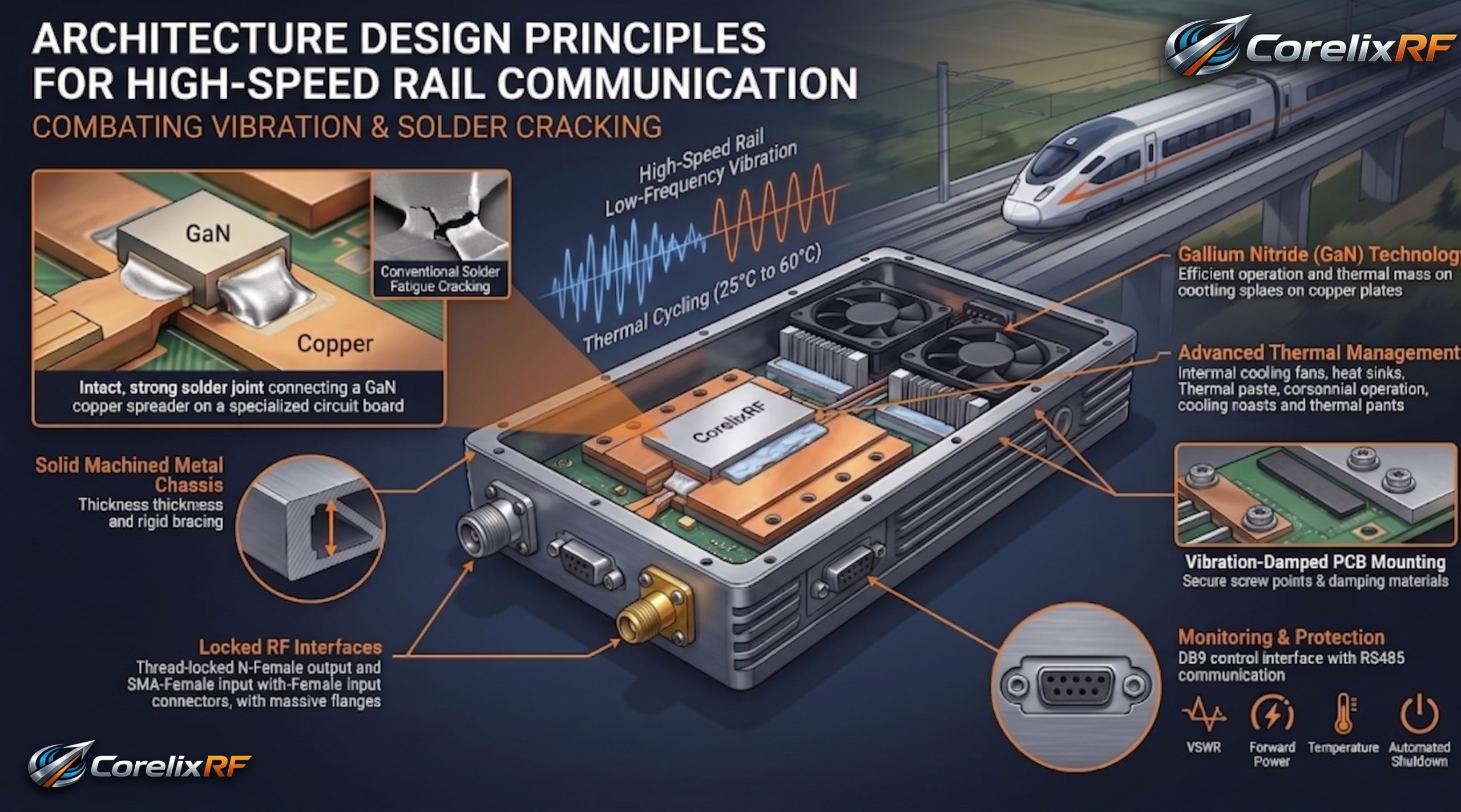
What Are The Architecture Design Principles For High-Speed Rail Communication Combating Low-Frequency Vibration Solder Cracking? Constant mechanical shaking destroys electronic equipment aboard modern trains. Your forward power monitor suddenly registers an unexpected drop during transit. Engineers check system logs finding repeated VSWR alarms triggering shutdown sequences. The root cause usually traces back toward microscopic solder fractures inside RF amplifiers. We solve this exact hardware nightmare using rigorous structural reinforcement techniques. Our factory produces ruggedized transmitter modules built specifically for punishing industrial applications. CorelixRF offers genuine engineering solutions rather than empty marketing promises. Here’s the deal. You need equipment capable of surviving continuous physical abuse without dropping critical data packets. Let us break down exact failure mechanisms plaguing conventional designs. We will explain how proper architecture guarantees reliable High-Speed Rail Communication performance.
1. What Are The Exact Failure Modes In High-Speed Rail Communication Architecture?
Field Diagnostic Observations
You might be wondering exactly what happens when trains accelerate rapidly. Constant low-frequency shaking creates havoc within standard commercial amplifier chassis designs. A train carriage moving across tracks generates distinct mechanical resonance frequencies. These vibrations travel directly through mounting brackets into your communication payload. Your spectrum analyzer suddenly displays massive noise floor spikes during operation. That indicates intermittent grounding faults caused by loose mechanical connections. Operators see system screens flashing red warning messages about weak current pins. We see this failure pattern repeatedly during field troubleshooting missions across transit networks. General purpose designs cannot withstand such sustained physical punishment without breaking down completely. Train environments present unique kinetic profiles tearing weak circuit boards apart. High-speed rail networks require specialized hardware architecture designed deliberately for extreme environments. Engineers must understand these physical realities before selecting system components for deployment. Ignoring mechanical realities leads directly toward catastrophic network outages costing millions. Your hardware must survive constant violent shaking without dropping critical data packets. We evaluate hardware failures tracking microscopic fractures inside delicate RF signal chains. True engineering requires matching structural durability against brutal environmental stress factors. Stop using fragile laboratory equipment inside heavy duty industrial rail applications.
Common Failure Modes
| Failure Type | Root Cause | System Symptom |
| Intermittent Drop | Loose SMA connector | VSWR alarm triggering |
| High Noise | Broken grounding pin | Spectrum analyzer spikes |
| Power Loss | Fractured GaN die solder | Forward power reduction |
2. Why Do Standard Amplifiers Fail Under High-Speed Rail Communication Low-Frequency Vibration?
Metal Rigidity
Commercial off-the-shelf modules utilize basic mounting techniques suitable for static lab environments. Those cheap chassis structures lack adequate internal bracing against constant shaking. When installed aboard trains experiencing continuous movement across rail networks. Low-frequency oscillation forces transfer directly into delicate internal circuit boards. What’s the real story? Cheap enclosures flex slightly under continuous mechanical stress over time. That flexing motion slowly weakens solder joints attaching critical RF transistors. Eventually those microscopic connections break open completely interrupting signal flow forever. Fast moving carriages produce severe low-frequency rumble destroying standard mounting hardware. We rely upon heavy duty 400x200x80 mm enclosures machined from solid metal blocks. This thick material prevents harmful chassis flexing during severe train vibrations. Proper mechanical design isolates delicate electronics from destructive external kinetic energy. We refuse standard aluminum extrusion boxes failing structural integrity tests immediately. Our factory mills thick metal walls providing absolute physical rigidity always. You cannot expect cheap sheet metal cases surviving decades aboard trains. We design heavy metal shielding preventing mechanical torque ruining delicate printed circuits. Your entire communication backbone depends upon robust physical chassis engineering practices.
3. What Is The Engineering Truth Behind Microscopic Solder Joint Cracking?
Thermal Cycling
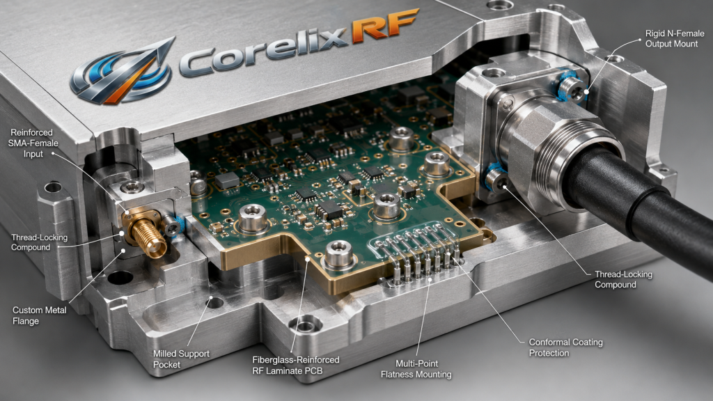
Thermal cycling combined with physical shaking creates a deadly hardware environment. As amplifiers heat up during transmission cycles their internal materials expand. A sudden drop in ambient temperature causes rapid material contraction afterward. This is where it gets interesting. Rail networks experience massive temperature fluctuations constantly throughout daily operation. We documented severe gain temperature drift issues occurring between 25°C and 60°C. That thermal stress fractures brittle lead-free solder connections over several months. Adding constant kinetic shaking accelerates this destructive physical process dramatically. Microscopic cracks develop underneath high-power GaN components mounted upon printed circuit boards. These tiny fractures increase electrical resistance causing localized hotspots underneath transistors. Those hotspots eventually burn through expensive packages permanently destroying your equipment. Our manufacturing process utilizes specialized high-reliability solder alloys preventing such failures entirely. We implement strict metallurgical controls guaranteeing strong bonds between components. The physical truth reveals how cheap solder cracks under transit vibration. We reject commercial manufacturing practices prioritizing cost savings over structural reliability. Every single solder joint must withstand simultaneous thermal shock and kinetic shaking.
Thermal And Kinetic Stress Factors
| Stress Element | Physical Effect | Component Impact |
| Temperature Drift | Solder expansion | Micro-cracks under GaN |
| Track Vibration | Board flexing | Broken trace lines |
| Repeated Power Cycling | Thermal shock | Component delamination |
4. How Does RF Connector Loosening Degrade High-Speed Rail Communication Link Budgets?
Impedance Mismatch
Vibration slowly unscrews standard threaded RF interfaces during long transit journeys. A loose connector immediately degrades your system return loss specifications catastrophically. That loose mechanical interface creates an unpredictable impedance mismatch fault immediately. Ready for the good part? Your 100 W rated output power reflects backward toward the active stages. This reflected energy triggers internal VSWR protection circuits causing immediate shutdown. Rail reliability depends heavily upon maintaining tight physical connections across networks. We specify rugged Input SMA-Female and Output N-Female connectors for a reason. These specific interface types provide superior mechanical stability under extreme vibration. Factory technicians apply precise torque settings during final assembly procedures manually. We also utilize specialized thread locking compounds preventing accidental loosening over time. Proper connector installation guarantees consistent link budgets across entire rail networks. A single loose threaded connection brings down an entire communication shelter. We secure every external interface anticipating constant violent movement during operation. You must physically lock down every coaxial connection eliminating movement completely. Our architecture prevents any connector rotation preserving critical impedance matching tolerances.
5. What Are The CorelixRF CRF-PA-6000M18000M-100W Design Solutions For High-Speed Rail Communication?
Factory Technology
CorelixRF designs heavy duty hardware targeting specific industrial engineering pain points. The CRF-PA-6000M18000M-100W operates flawlessly across a wide 6,000-18,000 MHz frequency range. We engineered this specific architecture specifically for demanding transit applications worldwide. Here is the truth. This unit delivers stable 100 W continuous RF power reliably. Our factory integrates advanced GaN technology guaranteeing high efficiency operation constantly. The massive 400x200x80 mm package provides immense thermal mass for active cooling. We implement air cooling methods keeping internal temperatures well below limits. Rail communication networks require this level of dedicated hardware engineering daily. We completely reject flimsy commercial modules built using inferior materials. You need genuine factory-direct technology lacking unnecessary visual marketing flair. This amplifier provides a massive 50 dB gain pushing signals through interference. We verify every specification against brutal physical testing profiles before shipping. Our engineers understand exactly what physical abuse ruins delicate electronic components. We build tanks meant for transmitting microwave energy across hostile environments. Your infrastructure requires industrial grade power amplifiers surviving harsh reality.
CorelixRF Technical Specifications
| Parameter | Min Value | Max Value |
| Frequency Range | 6,000 MHz | 18,000 MHz |
| Rated Output Power | 100 W | N/A |
| Gain | 50 dB | N/A |
6. How Does GaN Technology Inside CRF-PA-6000M18000M-100W Handle Thermal And Mechanical Stress?
Gallium Nitride
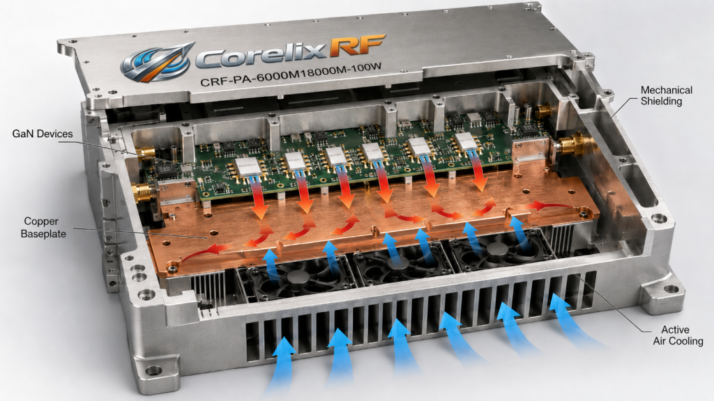
Gallium Nitride semiconductor material survives significantly higher operating temperatures than silicon. This inherent thermal robustness makes GaN perfect for harsh transit environments. The CRF-PA-6000M18000M-100W utilizes premium GaN devices mounted onto specialized copper spreaders. We must understand why. These spreaders match thermal expansion coefficients preventing microscopic solder fractures. We strictly control our internal factory assembly processes guaranteeing perfect bonding. Rail amplifiers must dissipate massive amounts of waste heat continuously. Our GaN architecture maintains strict gain flatness between -5 dB and 5 dB. A consistent noise floor measuring -35 dBm/MHz prevents communication signal degradation. We design equipment meant for decades of continuous industrial operation. You will never see cheap plastic components inside our rack-mount enclosures. We use real physics solving actual thermal dissipation problems inside chassis. Heavy copper baseplates draw heat away from active transistors very rapidly. That rapid heat transfer prevents localized hotspot formation ruining expensive dies. Our factory matches thermal impedance precisely across every single internal layer. We defeat high temperatures utilizing pure thermal mass and smart engineering.
7. What Architecture Strategies Prevent SMA-Female Input And N-Female Output Connector Loosening?
Coaxial Torque
We avoid relying solely upon standard panel mounting nuts for connectors. Our engineers design custom metallic flanges securing each RF interface directly. The thick 400x200x80 mm chassis features milled pockets cradling these heavy connectors. Truth be told. This mechanical design isolates external cable weight from internal circuit boards. Rail installations often involve routing heavy coaxial cables nearby active equipment. Train motion violently whips those cables around stressing traditional connector joints. Our N-Female output connector handles immense physical torque without breaking traces. We specify a maximum Input VSWR measuring strictly under 2:1 always. Any mechanical shifting would immediately ruin that critical impedance specification instantly. CorelixRF factory standards demand absolute physical rigidity from every single subassembly. We machine specific grooves holding connectors captive against violent twisting forces. This solid mechanical grounding prevents any strain reaching internal fragile components. You cannot trust basic lock washers stopping heavy cables from moving. We build physical barriers isolating kinetic energy away from our electronics.
RF Interface Mechanical Data
| Port Type | Connector Style | Maximum VSWR |
| RF Input | SMA-Female | 2:1 |
| RF Output | N-Female | N/A |
| Control Interface | DB9 RS485 | N/A |
8. How Do We Secure Internal PCB Traces Against 25°C To 60°C Temperature Drift And Vibration?
Conformal Coating
Standard FR4 circuit board materials warp terribly under severe heat loads. We specify advanced high-frequency laminates featuring specialized fiberglass reinforcement structures. These rigid boards resist flexing when subjected toward constant train vibrations. Consider the following. Rail communication systems face brutal operating environments constantly during service. We solved severe gain temperature drift problems occurring between 25°C and 60°C. Factory technicians apply conformal coating over all vulnerable weak current pins. This protective chemical layer prevents moisture ingress while adding structural support. We actively damp low-frequency kinetic energy before it reaches sensitive components. The CRF-PA-6000M18000M-100W maintains pristine signal integrity despite horrible ambient conditions. Our engineering team tests every unit against brutal physical shock profiles. We use multiple screw mounting points holding printed boards perfectly flat. That immense physical clamping force prevents resonant flexing destroying copper traces. We distribute mechanical stress evenly across the entire internal board surface. Your RF signals flow freely because we eliminate mechanical deformation entirely. We engineer reliability directly into the bare substrate material selection process.
9. What Monitoring Interfaces Protect The 100W Rated Output Power Integrity?
Telemetry Data
Blind operation aboard moving trains invites catastrophic system level hardware failure. Engineers need real-time telemetry data tracking every specific power amplifier metric. The CRF-PA-6000M18000M-100W features an industrial grade RS485 serial communication bus. You cannot ignore this. Our DB9 connector provides dedicated pins monitoring forward and reverse power. We include built-in protection against over-voltage and over-temperature fault conditions. Rail networks demand instantaneous automated shutdown during severe VSWR mismatch events. Pin 8 monitors internal module temperatures outputting precise detection voltage readings. Pin 4 allows remote attenuation adjustment handling variable input signal levels. These robust control interfaces survive the exact same vibrations as RF components. Our system architecture prioritizes equipment survival above all other design considerations. We process telemetry data locally triggering hardware protection subroutines without delay. You receive immediate diagnostic warnings predicting hardware failure before it happens. This proactive monitoring approach saves massive amounts of money during maintenance. We build intelligent power amplifiers defending themselves against hostile external factors.
DB9 Control Pin Definitions
| Pin Number | Function | Signal Type |
| Pin 1 & 2 | Serial Communication | RS485 |
| Pin 6 | Forward Power Monitor | Voltage Output |
| Pin 8 | Temperature Monitor | Voltage Output |
10. How Can Engineers Integrate The CRF-PA-6000M18000M-100W Into Existing High-Speed Rail Communication Enclosures?
DC Power Systems
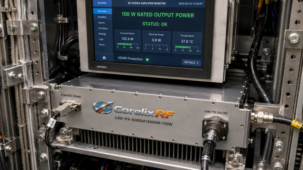
System integrators require straightforward mechanical mounting options for heavy amplifier modules. We supply detailed mechanical drawings for precise installation reference planning purposes. The massive 400x200x80 mm package requires adequate clearance facilitating active air cooling. Here is the bottom line. You must bolt this chassis directly onto load bearing structural rails. Using flimsy sheet metal brackets guarantees immediate vibration induced failure predictably. Rail payloads run off standard +24V to 32V DC power systems. Our 4-Pin Aviation connector handles heavy current draw securely during transit. We designed this unit specifically for test & measurement and communication applications. CorelixRF delivers professional industrial solutions solving actual physical hardware problems reliably. Stop wasting time debugging broken commercial modules failing field deployments constantly. We give you a massive metal block packed with RF power. You just need proper heavy duty bolts securing it down permanently. Our architecture handles the electrical and physical abuse without any complaints. We provide true engineering truth backing up every single datasheet specification.
Final Thoughts
Combating High-Speed Rail Communication vibration requires heavy duty physical architecture. The CRF-PA-6000M18000M-100W defeats microscopic solder cracking utilizing rigid mechanical enclosures. We protect your critical data links against severe mechanical environments. Our GaN technology maintains absolute performance under stress. Contact our factory engineers directly requesting detailed test data files today.
FAQ
Q1: What is the frequency range of the CRF-PA-6000M18000M-100W? The CorelixRF amplifier operates continuously between 6,000 MHz and 18,000 MHz. Q2: How does the built-in protection system work? It automatically shuts down operation detecting over-voltage, over-temperature, or high VSWR. Q3: What is the rated output power for this unit? This specific module delivers 100 W of continuous RF energy. Q4: Which control interface manages remote communication protocols? We utilize a robust RS485 serial connection through a DB9 port. Q5: What cooling method prevents thermal overload conditions? The chassis utilizes active air cooling dissipating heat from GaN components.
Translate rugged-site symptoms into a complete RF-chain review
Rugged RF issues often combine grounding, vibration, thermal range, connector retention, signal source stability and amplifier power margin. Share the site condition and acceptance evidence needed before choosing a platform.
Recommended next step: send the operating band, output power target, duty cycle, load condition, control interface, protection or thermal limits and required FAT documents. CorelixRF can review this How To Mount High-Speed Rail RF Amplifiers Against Vibration? requirement against standard RF amplifier platforms, RF front-end options and controlled customization paths.