
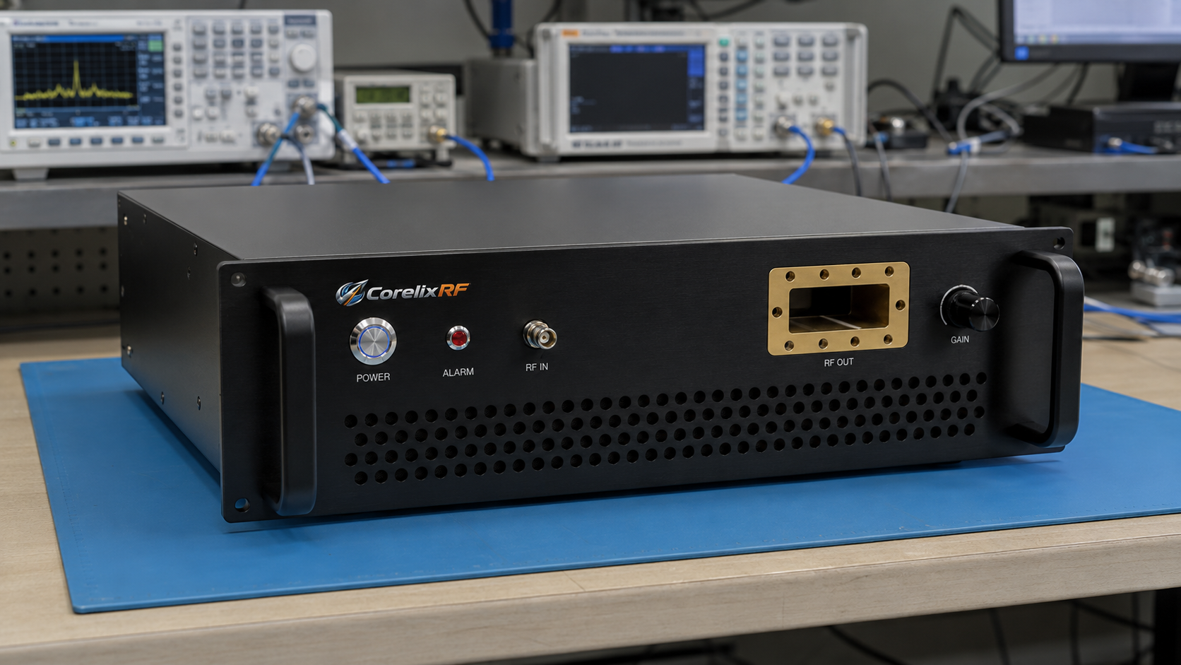
Hidden Faults in Complex Integrated Systems: Instantaneous Burnout Caused by RF Excitation and DC Power Supply Sequencing Errors represents a massive headache for field engineers managing radar racks. You power up your newly assembled rack, hear a pop, and smell burning semiconductor material instantly. That burnt smell means a costly GaN transistor has just vaporized due mostly toward improper bias timing. We fix this exact failure mode routinely at CorelixRF using hard-won hardware experience. My twenty years handling high-frequency power amplifiers shows that proper startup timing prevents catastrophic drain current spikes effectively. Engineers need rugged hardware featuring built-in sequencing logic rather than relying on flawed system-level software delays. Our specific methodology guarantees expensive test setups survive rigorous integration cycles without unexpected catastrophic hardware failures.
1. Why Do Power Sequencing Errors in Complex Integrated Systems Destroy GaN Amplifiers?
● Physics of GaN Depletion Mode Devices
● Drain Current Spikes During Unbiased RF Excitation
● Thermal Runaway Mechanisms
Here is the deal, gallium nitride transistors operate naturally as depletion-mode devices. This physical characteristic dictates that current flows freely unless a negative gate voltage pinches off that channel. Supplying drain voltage before establishing a solid negative gate bias causes immediate catastrophic device destruction. Electrons flood across that semiconductor junction without restriction, creating massive localized heating within microseconds. Adding premature RF excitation compounds this problem significantly. An incoming microwave signal swings that gate potential positive, demanding even higher peak currents from an already stressed drain supply. Those resulting thermal gradients crack delicate transistor dies instantly. We routinely examine failed modules where gold bond wires vaporized completely, leaving blackened carbon scoring across ceramic substrates. I have personally analyzed systems where technicians manually flipped rack breakers too quickly. Another common failure happens when automated test scripts initialize signal generators before power distribution units stabilize. A third classic example involves faulty grounding loops delaying that critical negative bias voltage momentarily. We design hardware specifically around these harsh physical realities rather than ignoring them.
Failure Modes From Bad Sequencing
| Sequencing State | Expected Result | Hardware Impact |
| Gate Unbiased, Drain Powered | Massive Current Draw | Immediate GaN Die Vaporization |
| RF Applied Before Gate Bias | Extreme Voltage Swings | Bond Wire Fatigue And Rupture |
| Proper Gate Before Drain | Controlled Quiescent Current | Safe Operational Status Maintained |
| RF Applied After Stable Bias | Normal Amplification | Reliable High-Power Output |
2. How Can Engineers Detect Hidden Faults in Complex Integrated Systems?
● Oscilloscope Triggering Techniques for Power Sequencing
● VNA Trace Collapse Diagnostics
● Identifying Transient Voltage Spikes
You might be wondering, how exactly do field technicians isolate these microsecond timing flaws? Using a high-speed mixed-signal oscilloscope provides absolute clarity when debugging startup sequences. You must configure single-shot triggers monitoring both gate bias lines and main drain supplies simultaneously. Capturing those critical initial fifty milliseconds reveals whether power supplies ramp smoothly or ring violently. Connecting a Vector Network Analyzer often highlights impending failures before total device destruction occurs. If you notice high-frequency VNA traces collapsing intermittently, that signifies creeping thermal damage within those active components. I recall debugging an electronic warfare jammer where output power dropped sporadically. We traced that degradation back toward minor voltage spikes during system reboot cycles. Another scenario involved a radar test bench showing massive standing wave alarms randomly. The root cause was RF bleeding from a switch matrix before amplifiers reached thermal equilibrium. Tracking down these transient events requires patience and high-bandwidth current probes. Our CorelixRF lab relies heavily on automated sequencing testers. We verify every single power ramp profile meticulously.
3. What Are Common Triggers For Power Sequencing Errors in Complex Integrated Systems?
● Relay Timing Mismatches in System Racks
● Firmware Glitches in Power Distribution Units
● Ground Loop Inductance Effects
Let us look closer, because software bugs frequently cause catastrophic hardware failures across integrated platforms. Modern power distribution units rely heavily on internal microcontrollers handling complex relay timing tasks. A simple firmware glitch can easily invert that required gate-before-drain startup sequence unpredictably. Mechanical relays also degrade over time, causing contact bounce that creates devastating voltage spikes. We see this degradation frequently inside older mobile radar trailers subjected primarily toward heavy vibration. Those vibrations loosen ground connections, creating massive inductive loops across system chassis backplanes. When high currents start flowing, those inductive loops cause ground bounce, shifting reference potentials drastically. This ground bounce tricks amplifier logic circuits into applying drive signals prematurely. For instance, a naval communication rack experienced frequent component failures during engine startup procedures. The ship’s generator voltage sags caused PDUs inside that rack to reset asynchronously. Another instance involved faulty solid-state relays leaking current across drain terminals while disabled. We always recommend hardware-level interlocks overriding software commands whenever possible.

4. How Does RF Excitation Timing Create Power Sequencing Errors in Complex Integrated Systems?
● CW Signal Generators Bleeding RF
● Switch Matrix Leakage During Power-Up
● Front-End Matching Network Saturation
Here is the kicker, applying microwave energy into an unbiased transistor practically guarantees immediate hardware vaporization. Commercial continuous-wave signal generators often leak substantial output power even while software disables their RF ports. This leakage easily saturates an unpowered amplifier’s front-end matching network, generating huge internal voltage swings. We measured up toward zero dBm leaking from one popular benchtop synthesizer during its boot cycle. When that leakage hits an unbiased GaN gate, it acts like a massive short circuit. A client once destroyed three consecutive modules because their custom switch matrix lacked sufficient isolation. During power-on, that matrix briefly routed full exciter power directly into our unpowered amplifier stages. Another customer ignored start-up delays, triggering their baseband waveform generators simultaneously alongside rack main power. Those complex modulated waveforms slammed into cold transistors, blowing apart output matching capacitors instantly. You must guarantee absolute RF silence until every internal bias voltage stabilizes completely. Our engineering teams utilize high-isolation PIN diode switches explicitly blocking inputs during initialization.
RF Excitation Timing Tolerances
| Timing Condition | RF Input Level | System Safety Status |
| Boot Up Phase | -60 dBm (Leakage) | Marginal Risk Exists |
| Bias Stabilizing | -30 dBm (Bleed) | High Risk Of Damage |
| Full Bias Active | 0 dBm (Nominal) | Safe Operating Zone |
| Power Down Phase | Must Be Muted | High Risk If Active |
5. Why Are Standard Protection Circuits Inadequate For Power Sequencing Errors in Complex Integrated Systems?
● Slow Response Times of Commercial Fuses
● Limitations of Basic Crowbar Circuits
● Failure of Passive Over-Voltage Diodes
What is the real story? Traditional protective components simply operate too slowly for modern high-frequency solid-state amplifiers. A standard glass fuse requires hundreds of milliseconds melting before breaking a faulty circuit entirely. Gallium nitride transistors melt themselves internally within microseconds when subjected toward unrestrained drain currents. Basic crowbar circuits utilizing thyristors also suffer from unacceptable latency issues during transient voltage spikes. By the time that thyristor latches fully, your expensive microwave die has already become molten slag. Passive over-voltage diodes add parasitic capacitance, which severely degrades high-frequency RF performance across broadband designs. We tested several commercial protection modules and found their insertion loss unacceptable for radar applications. One specific defense contractor attempted using standard industrial circuit breakers for rack-level protection. Those breakers never tripped fast enough during sequencing faults, resulting in massive equipment replacement costs. Another group tried implementing software-based current monitoring using generic analog-to-digital converters over Ethernet. Network latency rendered their protective algorithms completely useless during actual hardware faults. True protection requires dedicated, high-speed analog logic sitting right next to those amplifier stages.
6. How Does The CRF-PA-18000M40000M-40W Prevent Power Sequencing Errors in Complex Integrated Systems?
● Internal Bias Sequencing Logic
● High-Speed RF Blanking Mechanisms
● Over-Current Shutdown Millisecond Response
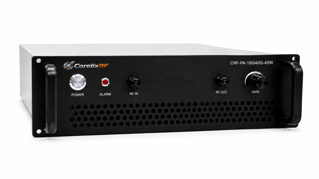
This is where it gets interesting, as our factory engineers solved these catastrophic timing issues directly. The CRF-PA-18000M40000M-40W Wideband RF Power Amplifier incorporates autonomous hardware bias sequencing logic internally. You simply provide raw AC 220V power, and our internal circuitry manages every delicate timing requirement. Our system establishes a stable negative gate voltage before slowly ramping that high-power drain supply. We engineered this specific model covering 18,000 to 40,000 MHz with robust GaN technology. It delivers forty watts rated output power while maintaining a strict 2:1 input VSWR. Built-in protection handles over-voltage, over-temperature, and over-current faults autonomously without requiring external computer intervention. If an operator accidentally applies excessive RF input prematurely, our optional over-drive protection kicks in instantly. One aviation control client replaced their unreliable legacy amplifiers with our CRF-PA-18000M40000M-40W units successfully. They previously suffered regular burnouts due to faulty rack controllers sending erratic startup commands. Since integrating our WRD180 waveguide output units, their field failure rate dropped absolutely toward zero. We guarantee stable 50dB gain performance regardless of minor external power supply fluctuations.
CRF-PA-18000M40000M-40W Specifications
| Parameter | Minimum | Typical | Maximum |
| Frequency Range | 18,000 MHz | Broadband | 40,000 MHz |
| Rated Output Power | 40 Watts | GaN Tech | Undefined |
| Input VSWR | Undefined | 2:1 Ratio | Undefined |
| Total Gain | 50 Decibels | Flatness | 6 Decibels |
7. What Measurement Tools Diagnose Power Sequencing Errors in Complex Integrated Systems?
● Multi-Channel Mixed Signal Oscilloscopes
● Directional Couplers For Reflected Power
● High-Bandwidth Current Probes
Now for the best part, equipping your laboratory correctly makes isolating these sequencing faults straightforward. A four-channel mixed-signal oscilloscope stands as the absolute mandatory tool for any serious integration engineer. You need adequate bandwidth capturing fast rising edges associated with gallium nitride switching transients. Standard multimeter readings provide zero value when analyzing microsecond-level timing discrepancies across multiple voltage rails. We strongly mandate utilizing high-bandwidth current probes clamped directly around main DC supply cables. These probes reveal exactly how much current an amplifier draws during specific microsecond intervals. Inline directional couplers allow continuous monitoring regarding both forward drive and reflected load power simultaneously. We once utilized this exact setup troubleshooting a satellite communications ground station experiencing random resets. Our high-speed probes detected massive current spikes correlating perfectly with unmuted synthesizer boot sequences. Another diagnostic session involved probing RS485 control lines while monitoring drain voltages on an oscilloscope. We discovered noisy communication buses were falsely triggering internal reset commands unpredictably during normal operation. Proper instrumentation separates guessing from knowing when tackling complex hardware integration challenges.
8. How Do You Implement Fail-Safe Power Sequencing Errors in Complex Integrated Systems?
● Hardware Interlocks For RF Drive
● Firmware Delays In System Controllers
● Redundant Drain Voltage Monitoring
Let us step back for a moment, evaluating how system architects should approach broad integration strategy. Relying solely upon software commands executing sequentially across a network invites disastrous timing collisions inevitably. Professional rack designs implement hard-wired interlock loops tying RF exciter muting circuits directly toward amplifier status. If an amplifier loses gate bias momentarily, that interlock physically breaks the RF drive path. We advise adding redundant drain voltage monitoring relays dropping main power if anomalies occur. Programming mandatory ten-second firmware delays between rack power-on and exciter initialization prevents countless catastrophic accidents. A radar manufacturer we consult with implemented dual-redundant opto-isolators verifying negative bias presence continuously. If their opto-isolator detects voltage sagging below nominal thresholds, it triggers a crowbar shutdown instantly. Another client utilized physical key-switches forcing operators through a strict, multi-step mechanical startup procedure manually. We always preach that hardware cannot crash, unlike complex operating systems running untested integration scripts. CorelixRF builds these fail-safes directly inside our chassis, taking that heavy burden off system integrators.
Fail-Safe Implementation Checklist
| Safety Mechanism | Implementation Method | System Benefit |
| RF Drive Interlock | Hardwired PIN Diode | Blocks Premature Signals |
| Gate Bias Monitor | Analog Comparator | Guarantees Channel Pinch-off |
| Drain Power Delay | Mechanical Relay Bank | Prevents Unbiased Current |
| Status Telemetry | RS485 / LAN Feedback | Provides Remote Diagnostics |
9. Can Thermal Damage Indicate Power Sequencing Errors in Complex Integrated Systems?
● Visual Inspection Of GaN Die
● Solder Melt Patterns On Output Matching
● Heatsink Temperature Gradients
Truth be told, performing a detailed post-mortem analysis on destroyed hardware yields massive engineering insights. When a transistor perishes due toward improper sequencing, the resulting thermal signature looks highly distinctive. We pull the lids off failed modules inspecting gallium nitride dies using high-powered stereo microscopes. A sequencing failure typically vaporizes drain bond wires completely, leaving distinct blast patterns across ceramic traces. Normal continuous-wave thermal overload usually causes gradual discoloration, whereas sequencing faults create microscopic explosive craters. Examining solder melt patterns around output matching networks reveals whether destruction occurred instantaneously or gradually. We often notice gold-tin eutectic solder reflowing violently following a massive uncontrolled current spike event. One returned warranty unit showed severe charring concentrated exclusively near its gate bias injection point. This specific burn pattern proved their rack controller applied positive voltage onto the negative terminal. Another autopsy revealed cracked substrates indicating thermal expansion happened faster than mechanical stress relief allowed. Recognizing these physical clues prevents engineers from chasing wrong solutions during complex system integration cycles.
10. What System Level Changes Eliminate Power Sequencing Errors in Complex Integrated Systems?
● Distributed Power Architecture Redesign
● Centralized Bias Control Modules
● Upgrading To CorelixRF Integrated Solutions
Here is the bottom line, patching flawed system architectures continually wastes extreme amounts of money. Upgrading toward a distributed power architecture isolates sensitive RF components from noisy industrial power rails. Designing dedicated centralized bias control modules guarantees timing precision across multiple amplifier racks synchronously. However, the most effective engineering solution involves utilizing amplifiers containing autonomous internal sequencing logic. Deploying units like the CRF-PA-18000M40000M-40W eliminates external dependency upon unreliable programmable logic controllers entirely. You simply provide raw mains voltage alongside a standard RS485 or LAN control connection. We handle the harsh physical realities governing high-frequency GaN operations inside our robust 4U chassis. A major defense contractor redesigned their entire mobile test platform around our self-contained RF solutions. They eliminated three separate power conditioning subsystems, saving substantial rack space and reducing thermal loads. Another integrator ditched their problematic custom bias controllers, relying exclusively upon our internal hardware safeguards. Engineering truth demands simplifying architectures by pushing critical safety logic directly into the terminal RF nodes.
System Architecture Upgrades
| Upgrade Approach | Financial Cost | Expected Reliability Gain |
| Custom Software Patches | Low Initial Spend | Very Poor Long-term |
| External Bias Controllers | Moderate Hardware Cost | Moderate Improvement |
| Redundant Power Supplies | High Space Penalty | Minor Timing Fixes |
| CorelixRF Self-Contained | Excellent Value | Total Elimination Of Faults |
To summarize key points, resolving power sequencing errors in complex integrated systems demands absolute hardware discipline. Relying on software delays invites catastrophic instantaneous burnout of expensive GaN transistors unexpectedly. Upgrading to self-contained units like the CRF-PA-18000M40000M-40W provides guaranteed autonomous bias protection fundamentally. Do not let flawed integration logic destroy your RF modules; review our datasheet today. Engage with CorelixRF engineers to build truly rugged, fail-safe microwave transmission architectures together.
FAQ Section
Q1: What is the primary cause of GaN amplifier burnout during system startup?
Instantaneous burnout occurs primarily when drain voltage hits before a stabilizing negative gate bias, causing massive uncontrolled current flow across the semiconductor junction.
Q2: How does the CRF-PA-18000M40000M-40W handle power sequencing autonomously? Our amplifier utilizes dedicated internal hardware logic establishing gate bias initially, then ramps drain power safely, completely ignoring external software timing flaws.
Q3: Why are standard system fuses ineffective against sequencing faults?
Commercial fuses take hundreds of milliseconds melting and breaking the circuit, whereas a GaN transistor will vaporize from over-current within a few microseconds.
Q4: What specific instruments detect microsecond timing errors in racks?
Engineers must use high-speed multi-channel mixed-signal oscilloscopes paired with high-bandwidth current probes capturing fast-rising edge transients accurately during power-up.
Q5: Can RF signal leakage cause catastrophic hardware failure during startup?
Yes, applying even low-level RF excitation from a synthesizer into an unbiased transistor saturates the matching network and induces fatal voltage swings instantly.
Make the lab setup and report curves part of the RFQ
Test-bench issues become easier to resolve when the RFQ lists signal source, cable loss, load condition, calibration setup, power sequencing, gain flatness, spurious limits and report format.
Recommended next step: send the operating band, output power target, duty cycle, load condition, control interface, protection or thermal limits and required FAT documents. CorelixRF can review this How to Troubleshoot Power Sequencing Errors Using Oscilloscopes? requirement against standard RF amplifier platforms, RF front-end options and controlled customization paths.