Selecting the ideal RF Power Amplifiers requires a meticulous balance of power, precision, and environmental resilience to ensure long-term system reliability. Choosing the wrong hardware can lead to catastrophic system failure, signal degradation, and unexpected project delays in high-stakes industries. By prioritizing specific technical benchmarks, you can avoid the ripple effect of thermal instability and spectral interference that often compromises complex missions. This guide provides a strategic framework to evaluate the critical specifications that define high-performance RF systems.
What Power Output Level Does Your Application Require?
Selecting an output power level depends on your target load requirements and safety margins for signal integrity. You must identify the maximum power delivered to the load while accounting for potential losses in cables and connectors. Understanding the difference between saturated and linear power ensures your system operates without clipping or damaging sensitive downstream components.
Understanding Saturated Power and P1dB
The P1dB compression point marks the boundary where your signal begins to lose linearity. If you push the amplifier beyond this point toward the saturated power (Psat) level, the output no longer increases predictably.
Look:
- P1dB is the most reliable metric for linear operation.
- Psat defines the absolute physical ceiling of the device.
- Operating near saturation often causes significant signal distortion.
The best part? Keeping your peak power below P1dB ensures your data remains clear and uncorrupted.
Peak vs. Average Power in Pulsed Systems
In applications like radar or digital communications, you must distinguish between the intensity of a burst and the sustained energy over time. High-intensity bursts require high peak power handling even if the average consumption remains low.
Think about it:
- Duty cycles dictate how much heat accumulates during operation.
- Pulse width affects the transient response of the internal circuitry.
- Failing to match peak requirements leads to early component fatigue.
You should always verify that the amplifier can sustain its maximum rated burst without voltage drops.
Matching Power to Load Requirements
The total power capability must align with the specific needs of your antenna or subsequent stages to prevent overdriving. You need to calculate the entire link budget to ensure the signal reaches its destination with sufficient strength.
The reality is this:
- Insufficient power results in failed long-distance connections.
- Excessive power can physically burn out smaller antennas or receivers.
- Precision matching reduces waste and improves overall system efficiency.
Key Takeaway: Always specify the P1dB compression point relative to your operating power to ensure the system stays within a safe, predictable range.
| Factor | P1dB (Linear) | Psat (Saturated) | Duty Cycle |
|---|---|---|---|
| Impact | Signal Integrity | Maximum Limit | Thermal Stress |
| Requirement | Must exceed peak signal | Defines hardware cap | Dictates cooling needs |
This table illustrates how power metrics interact to determine both the operational ceiling and the signal quality of your RF chain.
Is the Frequency Range Optimized for Your Signal?
Your frequency range must align with the specific operational bandwidth of your signal to ensure transmission success. RF Power Amplifiers are designed to handle specific bands, and using them outside these ranges results in severe gain loss. Choosing a broadband unit offers versatility, whereas a narrowband unit typically provides superior efficiency for dedicated tasks.
Broadband vs. Narrowband Performance
Broadband amplifiers cover several octaves, making them ideal for multi-purpose testing or electronic warfare applications. Conversely, narrowband models are tuned for a tight spectrum to maximize output power and power added efficiency.
Here is the key:
- Broadband units simplify inventory for varied project needs.
- Narrowband units reduce out-of-band noise naturally.
- Efficiency is generally higher in specialized narrowband designs.
The best part? You can choose a platform that scales with your future frequency requirements.
Maintaining Gain Flatness Across the Band
For frequency-agile systems, the variation in gain across the intended spectrum must remain minimal to prevent signal fluctuations. Significant gain dips can cause your transmitter to appear weaker at certain frequencies than others.
Look:
- Gain flatness affects the predictability of your link budget.
- Poor flatness requires complex external software compensation.
- High-quality designs maintain stability within +/- 1.0 dB.
Think about it: A flat response ensures that your signal remains consistent as you hop between channels.
Operating at Microwave and mmWave Frequencies
As frequencies move into the 18 GHz to 110 GHz range, signal loss and component tolerances become extremely sensitive. These high-frequency paths require specialized connectors and low-loss substrates to maintain performance.
The reality is this:
- mmWave signals are easily blocked by environmental obstacles.
- Cable losses increase dramatically as the frequency rises.
- Precision engineering is required to prevent internal signal reflections.
Key Takeaway: Evaluate performance plots across the entire frequency range to ensure gain remains stable at your specific operating points.
| Metric | Broadband Range | Narrowband Range | Gain Flatness |
|---|---|---|---|
| Advantage | Extreme Versatility | High Peak Efficiency | Signal Consistency |
| Trade-off | Lower Efficiency | Limited Utility | Higher Design Cost |
Analyzing the trade-offs between bandwidth and efficiency allows you to select the most cost-effective hardware for your specific spectrum.
How Much Gain Is Necessary for Effective Amplification?
Calculating necessary gain involves determining how much the input signal must be boosted to reach the desired output level. You must assess the output of your signal source, such as an SDR or generator, before selecting an amplifier. Insufficient gain will leave your system underpowered, while excessive gain may require attenuators to prevent saturation.
Small Signal vs. Large Signal Gain
Gain behaves differently depending on whether the amplifier is operating in its linear region or approaching its limit. Small signal gain is constant, but as the input increases, the large signal gain begins to drop.
Look:
- Small signal gain is measured at low input levels.
- Large signal gain reflects the reality of high-power operation.
- The difference between them indicates the health of the linear path.
The best part? Knowing both helps you map the entire dynamic range of your transmitter.
Input Power Sensitivity
The sensitivity of the amplifier determines the minimum signal level required to “drive” the unit to full power. If your source is too weak, you might need a pre-amplifier stage to bridge the gap.
Think about it:
- High sensitivity reduces the complexity of your signal source.
- Low sensitivity may require expensive high-output generators.
- Matching sensitivity prevents the introduction of unnecessary noise.
Here is the key: Ensure your signal source comfortably sits within the amplifier’s optimal input window.
Maintaining Gain Stability
Environmental factors, especially temperature shifts, can cause the gain of an amplifier to drift over time. High-performance units use temperature compensation circuitry to keep the output steady during long missions.
The reality is this:
- Heat causes gain to drop in most semiconductor materials.
- Uncompensated drift can ruin calibrated test measurements.
- Stability is vital for remote installations without active monitoring.
Key Takeaway: Calculate the total link budget to ensure the amplifier’s gain provides the desired output without exceeding input limits.
| Gain Type | Small Signal | Large Signal | Drift Tolerance |
|---|---|---|---|
| Usage | Linear Calibration | Actual Transmission | Environmental Reliability |
| Metric | dB (Constant) | dB (Compressed) | dB per Degree Celsius |
This comparison highlights why engineers must look beyond single-point gain values when designing for real-world environments.

Why Does Operating Efficiency Matter for Long-Term Costs?
Operating efficiency determines how much DC power is converted into useful RF signal versus wasted heat. Efficient RF Power Amplifiers are essential for battery-operated systems or remote sites where power is limited. By selecting high-efficiency models, you reduce both the electrical load and the cooling requirements of your facility.
Power Added Efficiency (PAE)
PAE is the primary metric used to judge how well an amplifier utilizes its supplied power while accounting for input energy. A high PAE percentage indicates a well-engineered unit that minimizes energy waste.
Look:
- PAE directly impacts the size of your power supplies.
- Lower efficiency leads to higher utility bills over time.
- GaN technology typically offers the best PAE in modern designs.
The best part? High PAE keeps your internal components cooler for longer service lives.
Impact on System Heat Generation
Energy that fails to become an RF signal is immediately transformed into heat within the amplifier housing. Inefficient systems require massive heatsinks or loud fans to prevent the hardware from melting.
Think about it:
- Every watt of waste heat must be moved away from the chip.
- Heat is the number one cause of component failure.
- Efficient systems allow for much smaller and lighter enclosures.
Here is the key: Efficiency is the secret to building high-power systems in small footprints.
Reducing Total Lifecycle Costs
While high-efficiency amplifiers may have a higher initial purchase price, they often save money over the life of the project. Reduced power draw and simplified cooling infrastructure lead to lower maintenance and operational overhead.
The reality is this:
- Small power savings add up over thousands of operating hours.
- Less heat means fewer fan failures and mechanical repairs.
- Efficient units are often eligible for green energy certifications.
Key Takeaway: Prioritize high-efficiency modules to minimize heat dissipation and reduce the size of required power supplies.
| Efficiency Metric | High PAE (>40%) | Low PAE (<20%) | Cooling Need |
|---|---|---|---|
| Result | Minimal Waste Heat | High Thermal Stress | Low vs. High Flow |
| Cost | Lower OPEX | Higher Utility Costs | Fanless vs. Active |
Efficient power conversion is the most effective way to lower the total cost of ownership while improving hardware lifespan.
Does the Amplifier Maintain Linearity Under High Load?
Linearity is the measure of how accurately the amplifier reproduces the input signal at a much higher power level. Non-linear amplification introduces unwanted harmonics and intermodulation products that can interfere with other users in the spectrum. For complex digital signals, high linearity is the only way to maintain a low bit error rate.
Harmonic Distortion and Intermodulation
When an amplifier becomes non-linear, it creates “ghost” signals at multiples of your target frequency. These harmonics can violate FCC or ETSI regulations and cause interference with adjacent communication channels.
Look:
- Second and third-order harmonics are the most common issues.
- Intermodulation (IMD) occurs when multiple signals mix poorly.
- Proper filtering and linear design mitigate these artifacts effectively.
The best part? Clean signals require less filtering, which reduces system complexity.
Signal Fidelity for Complex Modulation
Modern waveforms like 64-QAM or 256-QAM are extremely sensitive to phase and amplitude distortions. If your amplifier is not linear, the receiver will be unable to distinguish between different data symbols.
Think about it:
- Non-linearity “smears” the signal constellation on a plot.
- High distortion leads to dropped packets and slow data speeds.
- Linearity is essential for high-throughput 5G and satellite links.
Here is the key: Your data is only as good as the linearity of your final stage.
Class A vs. Class AB Operation
Choosing the right amplifier class involves a direct trade-off between absolute linearity and electrical efficiency. Class A offers the purest signal but stays “on” constantly, whereas Class AB balances purity with lower power draw.
The reality is this:
- Class A is preferred for laboratory-grade precision.
- Class AB is the industry standard for mobile communications.
- Modern digital pre-distortion can help Class AB mimic Class A purity.
Key Takeaway: For modulated signals, ensure the amplifier operates sufficiently below the P1dB point to maintain linear performance.
| Class | Linearity | Efficiency | Ideal Use |
|---|---|---|---|
| Class A | Excellent | Poor | Lab / Instrumentation |
| Class AB | Good | Moderate | Comms / Infrastructure |
Selecting the correct operating class ensures that your system remains compliant with spectral masks while meeting power targets.
How Will You Manage Heat and Thermal Dissipation?
Reliable operation of RF Power Amplifiers depends entirely on moving heat away from the sensitive semiconductor junctions. High-power units generate significant thermal energy that must be dissipated through active or passive means. If heat is not managed, the internal temperature will rise until the device enters thermal shutdown or suffers permanent damage.
Active vs. Passive Cooling Strategies
Passive cooling relies on heavy metal heatsinks and natural airflow, making it silent and maintenance-free. Active cooling uses fans or liquid-cooled cold plates to move massive amounts of heat in high-density environments.
Look:
- Fans are effective but introduce mechanical points of failure.
- Liquid cooling is required for multi-kilowatt systems.
- Passive cooling is best for remote or “fit and forget” installs.
The best part? Proper thermal design can double the expected life of your amplifier.
Impact on Long-Term Reliability
Excessive heat accelerates the aging of capacitors, solder joints, and the RF transistors themselves. Maintaining a low baseplate temperature ensures that the system meets its rated Mean Time Between Failures (MTBF).
Think about it:
- A 10-degree rise can cut the life of electronics in half.
- Thermal cycling causes physical stress on internal connections.
- Reliable cooling prevents “gain droop” during long transmissions.
Here is the key: The coolest amplifier is always the most reliable amplifier.
Integrating Heatsinks and Thermal Interfaces
The mechanical design must account for the physical space required for heatsinks and the quality of the thermal paste used. Even the best heatsink is useless if there is poor contact between the amplifier and the metal.
The reality is this:
- Air gaps between surfaces act as thermal insulators.
- High-quality thermal interface materials (TIM) are mandatory.
- Mounting pressure must be consistent to ensure even heat flow.
Key Takeaway: Verify that your integration environment can dissipate the “waste heat” calculated from the amplifier’s efficiency rating.
| Cooling Method | Passive (Heatsink) | Active (Fans) | Liquid (Cold Plate) |
|---|---|---|---|
| Power Limit | <50 Watts typically | 50 – 500 Watts | >500 Watts |
| Maintenance | None | Low (Fan Cleaning) | Moderate (Pump/Fluid) |
Thermal management is a critical integration step that determines whether your hardware survives the rigors of field deployment.
Is the System Protected Against High VSWR Conditions?
The Voltage Standing Wave Ratio (VSWR) indicates how well your amplifier is matched to its load, such as an antenna. A high VSWR means that power is being reflected back into the amplifier rather than being radiated. Without internal protection, this reflected energy can cause rapid overheating and catastrophic failure of the output transistors.
Risks of Reflected Power
Reflected power creates standing waves that produce high voltage peaks at specific points in the circuitry. These peaks can exceed the breakdown voltage of the semiconductor, leading to an immediate “blown” unit.
Look:
- A broken antenna cable is the most common cause of high VSWR.
- Reflections cause the amplifier to work harder for less output.
- Ice or water on an antenna can suddenly change the match.
The best part? Modern isolators can “soak up” reflected power to save the unit.
Internal Protective Circuitry
High-quality amplifiers include smart sensors that monitor reflected power in real-time. These systems can automatically reduce the output power or shut the unit down entirely if a dangerous mismatch is detected.
Think about it:
- Protection circuits are like an insurance policy for your hardware.
- “Fold-back” protection keeps you on the air at a safer, lower power.
- Visual alarms help technicians diagnose antenna issues quickly.
Here is the key: Built-in protection prevents a simple cable failure from becoming a $10,000 repair.
Handling Mismatched Loads in Field Conditions
In tactical or mobile environments, you cannot always guarantee a perfect 50-ohm match. Ruggedized amplifiers are designed to survive “open” or “short” circuit conditions for short durations during setup or damage.
The reality is this:
- Antennas get bent, hit by branches, or disconnected.
- High VSWR tolerance is a requirement for military-grade gear.
- Testing your system into a dummy load is the safest way to start.
Key Takeaway: Always opt for amplifiers with built-in VSWR protection if the load conditions are not perfectly controlled.
| VSWR Level | 1.0:1 to 1.5:1 | 2.0:1 to 3.0:1 | >5.0:1 |
|---|---|---|---|
| Status | Perfect Match | Moderate Reflection | Critical Danger |
| Action | Full Power | Possible Fold-back | Shutdown / Damage |
Protecting against reflected power is the most important safety feature to look for when deploying hardware in the field.
How Is Signal Fidelity Preserved During Transmission?
Signal fidelity refers to how well the RF Power Amplifiers preserve the nuances of the original waveform. In high-speed data links, even tiny errors in phase or amplitude can prevent the receiver from decoding information. By selecting an amplifier with low noise and high timing accuracy, you ensure your data reaches its destination without corruption.
Minimizing Phase Noise and Jitter
Phase noise describes the random fluctuations in the phase of the signal, which can “blur” the edges of digital symbols. High-quality amplifiers are designed to add as little noise as possible to the signal chain.
Look:
- Phase noise is critical for high-order modulation like 1024-QAM.
- Jitter can cause synchronization errors in timing-sensitive labs.
- Low-noise components are the foundation of signal purity.
The best part? Clear signals allow for much higher data throughput.
Spectrum Mask Compliance
Regulatory bodies like the FCC require that your signal stays within a very specific frequency “box.” If your amplifier distorts the signal, energy will “leak” into neighboring bands, potentially leading to fines or legal issues.
Think about it:
- Spectral regrowth is a symptom of a non-linear amplifier.
- Compliance ensures you don’t interfere with emergency services.
- Clean output reduces the need for expensive external filters.
Here is the key: Fidelity is about being a good neighbor in the RF spectrum.
Error Vector Magnitude (EVM)
EVM is a comprehensive metric that combines noise, distortion, and phase errors into a single percentage. A lower EVM percentage means the amplifier is doing a better job of maintaining the integrity of the original signal.
The reality is this:
- EVM is the ultimate report card for a communication system.
- High-quality amplifiers are tested for EVM across their full power range.
- If your EVM is high, your data speed will naturally drop.
Key Takeaway: Review unit-level test data to confirm the amplifier meets the specific EVM requirements of your modulation protocol.
| Metric | Phase Noise | Spectral Mask | EVM |
|---|---|---|---|
| Focus | Timing Accuracy | Regulatory Compliance | Overall Signal Quality |
| Unit | dBc/Hz | Pass / Fail | Percentage (%) |
Analyzing fidelity metrics ensures that your system doesn’t just transmit power, but transmits usable and compliant information.
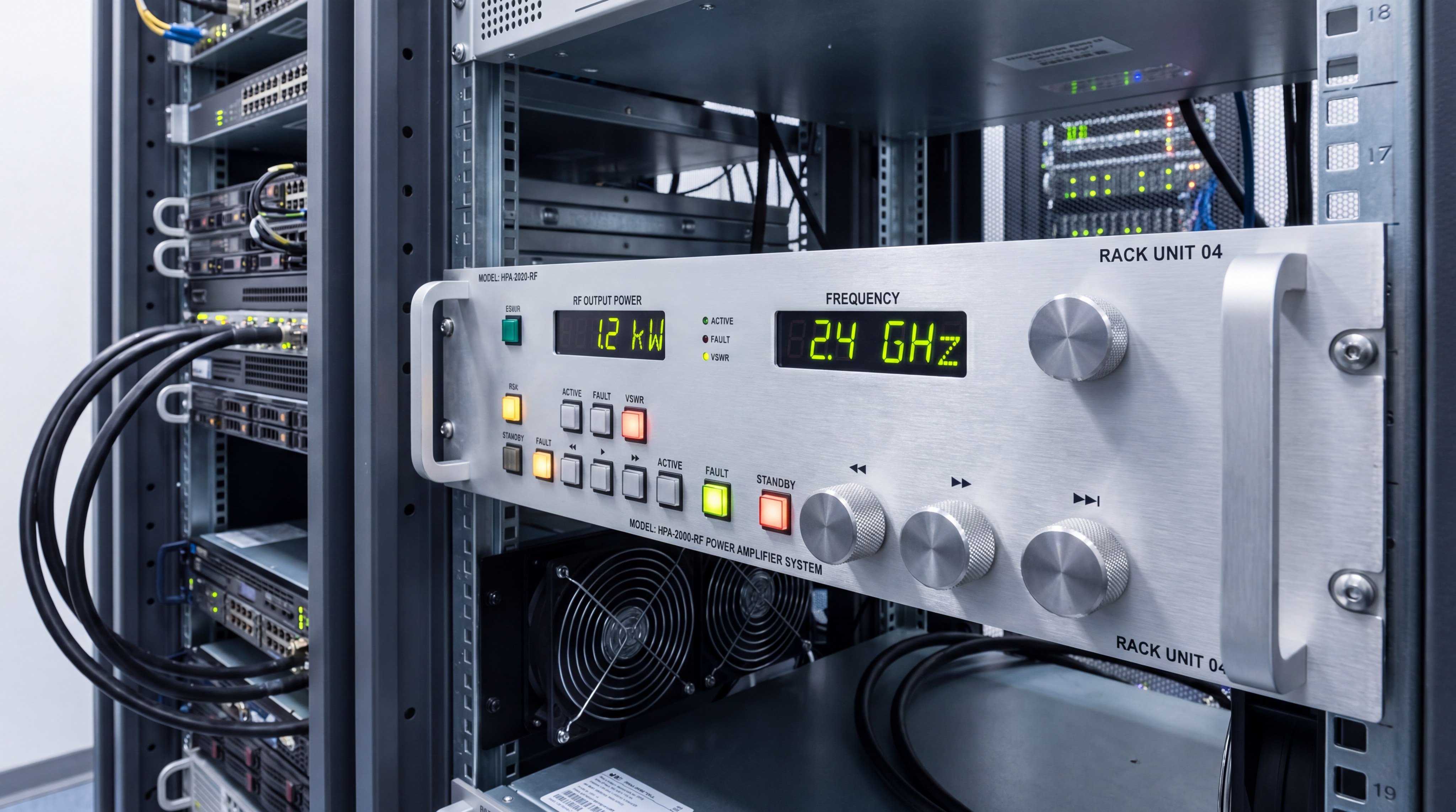
What Mechanical and Form Factor Constraints Exist?
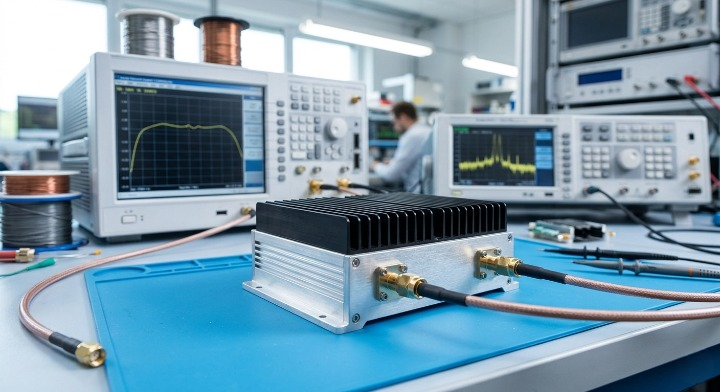
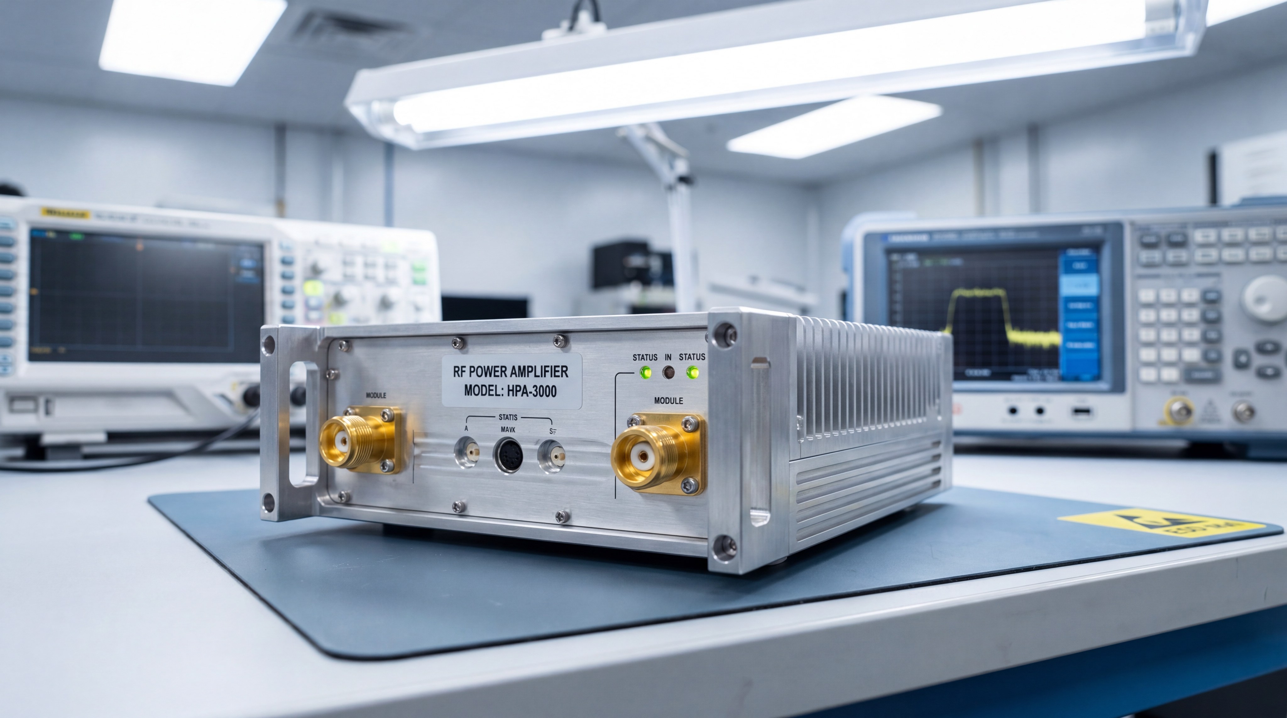
The physical design of an amplifier must fit into the space provided by your system architecture. Small, rugged modules are necessary for UAVs or handheld devices, while 19-inch rack-mount systems are the standard for laboratories. You must also consider the weight of the unit and the type of connectors required to interface with your existing cables.
Module vs. Rack-Mount Configurations
Module amplifiers are compact and designed to be integrated into larger custom enclosures. Rack-mount systems are standalone units with built-in power supplies and cooling, ready to be bolted into a standard equipment rack.
Look:
- Modules offer the most flexibility for OEM designs.
- Rack-mounts are easier to swap and maintain in a lab setting.
- Enclosure choice dictates how you handle power and cooling.
The best part? You can get the same RF performance in vastly different physical packages.
Weight Considerations for Mobile Platforms
For drones, satellites, or man-portable equipment, every gram of weight reduces battery life or mission range. You must balance the need for high power with the physical weight of the amplifier and its cooling hardware.
Think about it:
- Aluminum is lighter than copper but has lower thermal conductivity.
- High-efficiency designs require smaller, lighter heatsinks.
- Lightweight units are often more expensive due to advanced materials.
Here is the key: Focus on the power-to-weight ratio for any mobile application.
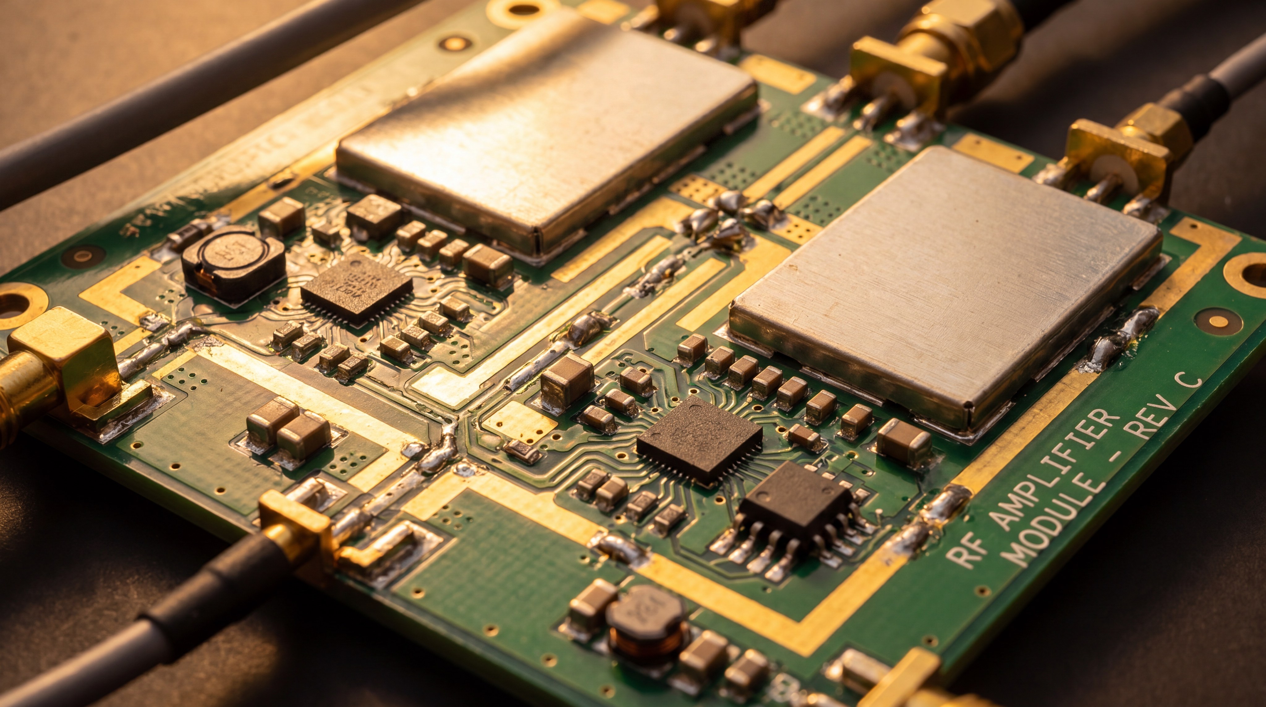
Connector and Interface Standardization
The choice of RF connectors must match your frequency and power levels. SMA connectors are standard for low power, while N-type or larger connectors are required to handle high-wattage signals without melting.
The reality is this:
- Using the wrong connector can introduce significant signal loss.
- Control interfaces like Ethernet or RS485 allow for remote monitoring.
- Standardized connectors make field repairs much faster and easier.
Key Takeaway: Confirm that the physical dimensions and connector orientations fit within your system’s mechanical envelope.
| Format | Small Module | Medium Ruggedized | 19-inch Rack |
|---|---|---|---|
| Typical Use | UAV / Drone | Vehicle / Outdoor | Lab / Data Center |
| Benefit | Low Weight | High Durability | Integrated Power/Cooling |
Mechanical planning prevents costly rework and ensures your hardware survives the physical shocks of its operating environment.
Does the Unit Meet Reliability and Certification Standards?
Final selection should always favor RF Power Amplifiers manufactured in ISO-certified facilities that follow rigorous testing protocols. Military and aerospace applications often require specific certifications to ensure the hardware can survive extreme vibration and temperature. Demanding unit-level test data rather than “typical” specifications protects you against manufacturing variance.
ISO 9001 and Military Standards
Manufacturing standards ensure that the unit you receive today is identical to the one you receive next year. ISO 9001 certification indicates a company that takes quality management and process control seriously.
Look:
- Mil-STD-810 covers environmental testing like shock and salt spray.
- Standards reduce the risk of “infant mortality” in new units.
- Certified vendors provide better long-term support and traceability.
The best part? Standardized testing proves the hardware can handle your worst-case scenarios.
The 3-Stage Inspection Process
A robust manufacturing process includes inspection of incoming parts, monitoring during assembly, and a final test of the finished unit. This triple-check ensures that no defective components make it into the final product.
Think about it:
- Components are screened for counterfeit or out-of-spec parts.
- In-process checks catch assembly errors before they are sealed.
- Final testing validates every RF metric against the datasheet.
Here is the key: Don’t settle for “sample testing” when your mission is on the line.
Documentation and Field Life Expectancy
You should receive a comprehensive datasheet and, ideally, a verified test report for the specific serial number you purchased. Documentation of the Mean Time Between Failures (MTBF) helps you plan for long-term maintenance.
The reality is this:
- Good documentation makes system integration much faster.
- MTBF data allows for proactive replacement before a failure occurs.
- Detailed reports help in troubleshooting if a system underperforms.
Key Takeaway: Demand unit-level test reports rather than “typical” specifications to guarantee the performance of the specific hardware you receive.
| Standard | ISO 9001 | MIL-STD-810 | Unit Test Report |
|---|---|---|---|
| Purpose | Process Consistency | Environmental Toughness | Performance Guarantee |
| Value | Vendor Reliability | Field Survival | Integration Confidence |
Quality certifications are the final proof that your chosen amplifier will perform reliably throughout its intended service life.
*
FAQ
- Can I use a broadband amplifier for narrowband tasks?
Yes, broadband units are highly versatile and can handle narrowband tasks, though they may offer slightly lower efficiency than a dedicated narrowband model. - What’s the best way to calculate my required gain?
Subtract your minimum signal source level (in dBm) from your target output power (in dBm); the resulting difference is the minimum gain you need. - Can I request specific test data for my serial number?
Professional manufacturers provide unit-level test reports (covering gain, power, and VSWR) as a standard part of the delivery process. - What’s the best cooling method for a 1kW system?
For systems reaching or exceeding 1kW, liquid-cooled cold plates or high-pressure forced-air systems are typically required to manage the massive heat load. - Can I integrate these modules into a custom chassis?
Most modular amplifiers are designed for custom integration, provided you match the mechanical mounting, power supply, and thermal requirements.
Conclusion
Selecting the right RF amplifier involves balancing electrical performance with mechanical and environmental realities. By systematically evaluating power, frequency, and thermal needs, you can ensure system longevity and signal purity. To explore a wide range of standard and custom solutions tailored to your specific engineering requirements, contact us today to discuss your project with an RF specialist.