
How to select the right RF power amplifier? You must begin by identifying the precise frequency range, required output power, and signal linearity needs of your specific application. Selecting an F Power Amplifier often presents a technical challenge for engineers who must balance sophisticated modulation schemes with strict thermal constraints. A mismatch in these parameters can lead to signal distortion or hardware failure, stalling your project and increasing costs. Fortunately, by following a structured evaluation of technical specifications, you can secure a solution that ensures robust performance and long-term reliability.
What Is the Required Frequency Range?
The required frequency range is the specific spectrum between the lowest and highest frequencies where your system must operate efficiently. When choosing an F Power Amplifier, you must verify that its bandwidth encompasses your entire signal spectrum to avoid gain roll-off or signal attenuation at the band edges.
Defining Operational Bandwidth
Bandwidth determines the flexibility of your hardware across various communication protocols. For wideband applications, the amplifier needs to maintain a consistent response over multiple octaves without requiring hardware retuning.
Managing Frequency Stability
Frequency stability ensures that the gain and phase of the signal remain predictable throughout the operational range. High-frequency applications often face greater path loss, making stable amplification even more critical.
Here is the kicker:
Operating at the edge of a rated frequency band can lead to unpredictable non-linear behavior.
- HF/VHF: 9 kHz to 225 MHz for legacy systems.
- Broadband: 30 MHz to 6 GHz for modern SDR platforms.
- Microwave: 18 GHz to 40 GHz for satellite links.
- Millimeter-Wave: Up to 110 GHz for advanced research.
Key Takeaway: Always select a frequency range that offers a 10-20% margin beyond your actual signal needs to ensure edge-of-band stability.
| Frequency Category | Typical Range | Primary Application |
|---|---|---|
| Broadband | 30 MHz – 6 GHz | UAV and SDR Integration |
| Microwave | 6 GHz – 18 GHz | Defense and SATCOM |
| Millimeter-Wave | 18 GHz – 110 GHz | 5G and Radar Systems |
Analyzing frequency requirements early prevents the need for complex filtering stages later in the integration process.

How Much Output Power Is Needed?
You determine output power by calculating the total signal reach required while accounting for cable losses, connector attenuation, and antenna gain. Selecting an F Power Amplifier requires a careful balance between meeting minimum signal-to-noise ratios and avoiding excessive power consumption.
Peak versus Average Power
Modern digital modulation schemes often have high peak-to-average power ratios (PAPR). Your amplifier must have enough headroom to handle these peaks without clipping the signal or introducing distortion.
Evaluating System Path Loss
Every component between the amplifier and the antenna introduces loss that must be compensated for by the amplifier’s output stage. Engineers should factor in a safety margin to account for environmental variations or component aging.
But wait, there is more.
If you over-specify power, you might end up with unnecessary cooling requirements and a larger physical footprint.
- Low Power (20W-50W): Ideal for small UAV platforms.
- Medium Power (100W-500W): Standard for lab testing and EMC.
- High Power (1kW+): Required for long-range radar and simulation.
Key Takeaway: Ensure the rated P1dB or saturation power of the hardware exceeds your peak system requirement by at least 3 dB.
| Power Metric | Definition | Critical For |
|---|---|---|
| CW Power | Continuous wave output | Stable transmissions |
| Peak Power | Maximum burst output | Complex modulation |
| Gain at P1dB | Power at 1dB compression | Linearity limits |
Proper power budget calculation is the most effective way to prevent thermal runaway in high-power RF systems.
Which Operating Mode Fits the Signal?
The operating mode is determined by whether your signal is a constant continuous wave or a series of high-energy bursts. An F Power Amplifier must be architecturally designed to handle the specific duty cycle and waveform characteristics of your input signal.
Continuous Wave Applications
Continuous wave (CW) mode is the standard for communication links and signal generation. In this mode, the amplifier must be capable of dissipating heat constantly over long periods of operation.
Pulsed Mode Performance
Pulsed mode allows the amplifier to reach much higher peak power levels because the “off” time allows for thermal recovery. This is essential for radar applications where high-energy bursts are sent at specific intervals.
The best part?
Pulsed amplifiers can often deliver five to ten times the power of a similarly sized CW unit.
- Duty Cycle: The ratio of active pulse time to total time.
- Pulse Width: The duration of a single signal burst.
- Rise/Fall Time: The speed at which the amplifier reaches full power.
Key Takeaway: Using a CW-rated amplifier for high-duty-cycle pulses can lead to overheating if the thermal design is not specifically validated.
| Mode | Strength | Best Signal Type |
|---|---|---|
| CW | Constant stability | FM / AM / SDR |
| Pulse | High peak power | Radar / LIDAR |
| Combined | Versatility | Multi-purpose Lab Test |
Selecting the correct mode optimizes the power-to-size ratio, ensuring your system remains compact yet effective.
How Does Power Gain Affect the System?
Power gain is the ratio of output power to input power, typically expressed in decibels (dB), which indicates the amplification strength of the unit. Choosing the right F Power Amplifier involves selecting a gain level that reaches your target output without overdriving the input stage.
Balancing High Gain and Noise
High gain is beneficial for low-power signal sources like SDRs, but it can also amplify unwanted noise. You must evaluate the noise figure of the amplifier to ensure the signal-to-noise ratio remains within acceptable limits.
Gain Control and Stability
Many advanced amplifiers feature internal gain control to compensate for temperature fluctuations. This ensures that the output remains stable even as the hardware heats up during intense operation.
But that is not all.
Variable gain features allow you to fine-tune the system performance during the final stages of hardware integration.
- Input Level: The power provided by your signal source.
- Gain (dB): The multiplier for the signal strength.
- Saturation: The point where increasing input no longer increases output.
Key Takeaway: Aim for a gain level that allows your signal source to operate in its most linear region, typically around -10 to 0 dBm.
| Gain Level | Typical Usage | Advantage |
|---|---|---|
| 30 – 40 dB | Standard SDR Integration | Simplifies the RF chain |
| 50 – 60+ dB | Long Range Comms | Drives high output from weak sources |
| Variable Gain | Precision Testing | Adjusts for varying path loss |
Consistency in gain prevents data packet loss in high-speed digital communication environments.
Why Does Gain Flatness Matter Most?
Gain flatness measures the variation in amplification levels across the entire operating frequency band of the hardware. For an F Power Amplifier, poor flatness can distort wideband signals, causing some frequencies to be amplified more than others.
Impact on Wideband Signals
When using wideband modulation like OFDM, every sub-carrier must be amplified equally. Significant gain ripples can cause phase errors and increase the bit error rate (BER) of your communication link.
Minimizing Signal Distortion
Amplifiers with high gain flatness, typically within +/- 1.5 dB, ensure that the frequency response is predictable. This is particularly important for frequency-hopping systems where the signal moves rapidly across the band.
Believe it or not:
A perfectly flat response is impossible, but modern solid-state designs have brought ripples down to negligible levels.
- Flatness (dB): The peak-to-peak variation in gain.
- Slope: A linear change in gain over a frequency range.
- Ripple: Small, periodic variations across the bandwidth.
Key Takeaway: Prioritize gain flatness if your application involves high-data-rate transmission or precision laboratory measurements.
| Specification | Target Value | Application Importance |
|---|---|---|
| Broadband Flatness | +/- 1.0 dB | 5G and Wideband SDR |
| Narrowband Flatness | +/- 0.5 dB | Specialized Filtered Comms |
| Thermal Flatness | +/- 2.0 dB | Outdoor / Harsh Environments |
Maintaining gain flatness across the entire band is essential for preserving the spectral mask of complex digital waveforms.
How Does Efficiency Impact Cooling?
Efficiency is the ratio of RF output power to the DC power consumed, directly determining how much energy is converted into waste heat. When selecting an F Power Amplifier, higher efficiency reduces the burden on your thermal management system and power supply.
Power Added Efficiency (PAE)
PAE is a critical metric for power-sensitive applications like airborne or battery-operated systems. It accounts for the input RF power, providing a more accurate picture of how much energy is truly being amplified.
Heat Dissipation Challenges
Inefficient amplifiers act like heaters, requiring large heat sinks or loud cooling fans. This not only increases the size of your system but can also introduce mechanical vibration that affects other sensitive electronics.
Here is the kicker:
Gallium Nitride (GaN) technology has revolutionized efficiency, allowing for much smaller and cooler-running hardware.
- DC Consumption: The total power drawn from the source.
- Waste Heat: The energy lost as thermal output.
- Efficiency (%): The metric for energy conversion quality.
Key Takeaway: Choose high-efficiency GaN-based amplifiers to reduce operational costs and simplify your mechanical design.
| Technology | Typical Efficiency | Thermal Impact |
|---|---|---|
| GaAs | 15% – 25% | Moderate Heat |
| GaN | 35% – 55% | Low Heat / High Power |
| Silicon (LDMOS) | 20% – 30% | High Heat for High Power |
Lowering thermal output extends the Mean Time Between Failures (MTBF) for the entire integrated system.
What Role Does Linearity Play?
Linearity defines how accurately an amplifier reproduces the input signal without adding unwanted harmonics or intermodulation products. For an F Power Amplifier, high linearity is essential for maintaining signal integrity in dense electromagnetic environments.
Third-Order Intercept Point (TOI)
The TOI or IP3 is a theoretical value that indicates where the power of the third-order intermodulation products equals the power of the fundamental signal. A higher TOI value indicates a more linear amplifier that can handle multiple signals simultaneously.
Managing Harmonic Distortion
Non-linear amplification creates harmonics—multiples of the original frequency—that can interfere with other communication bands. Proper design and filtering are required to suppress these signals to acceptable levels.
The best part?
A highly linear amplifier allows you to use more complex modulation schemes like 256-QAM for higher data speeds.
- P1dB: The 1 dB compression point.
- ACLR: Adjacent Channel Leakage Ratio.
- IMD: Intermodulation Distortion products.
Key Takeaway: If your signal has a high peak-to-average ratio, select an amplifier with a TOI at least 10 dB above your peak output power.
| Metric | Importance | Target |
|---|---|---|
| TOI (IP3) | Multi-carrier performance | High (> 45 dBm) |
| Harmonics | Spectral purity | < -30 dBc |
| ACLR | Channel interference | < -45 dBc |
Linear performance is the primary factor in meeting regulatory spectral mask requirements for wireless transmission.
Why Is Impedance Matching Essential?
Impedance matching ensures that the resistance of the amplifier matches the 50-ohm standard of the cables and antennas in your system. An F Power Amplifier must be perfectly matched to prevent signal reflections that can damage the hardware.
Understanding VSWR
The Voltage Standing Wave Ratio (VSWR) measures how much power is reflected back into the amplifier from the load. A high VSWR indicates a mismatch that causes energy to be lost and heat to build up at the output transistors.
Protecting the Output Stage
High-quality amplifiers include protection circuits that detect high VSWR and automatically reduce power or shut down. This prevents catastrophic failure if an antenna is damaged or a cable is disconnected during operation.
Look at it this way:
A 3.0:1 VSWR reflects 25% of your power back into the amplifier, doubling the internal thermal load.
- 50 Ohms: The industry standard for RF impedance.
- Return Loss: The reflected power expressed in dB.
- Isolation: Protection against backward-flowing energy.
Key Takeaway: Use high-quality 50-ohm connectors and cables to keep your VSWR below 1.5:1 for maximum safety and efficiency.
| VSWR Ratio | Reflected Power | Integration Status |
|---|---|---|
| 1.0:1 | 0% | Perfect Match |
| 1.5:1 | 4% | Ideal for Operation |
| 2.0:1 | 11% | Acceptable Limit |
Consistent impedance matching is the foundation of a stable and durable RF transmission chain.
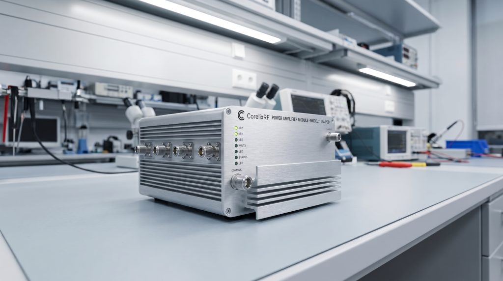
How Does the Form Factor Change Use?
The form factor refers to the physical size, weight, and mounting style of the amplifier, which must align with your installation environment. From compact modules to large rack-mounted systems, the F Power Amplifier must fit within your mechanical constraints.
Modules vs. Rack-Mount Systems
Small modules are designed for integration into larger hardware enclosures, such as UAVs or portable communication hubs. Rack-mounted systems are more suitable for laboratory or data center environments where space is standard and accessibility is key.
Weight and Portability Concerns
For airborne applications, every gram of weight matters, requiring highly integrated designs with lightweight aluminum housings. In contrast, benchtop units for lab use prioritize thermal mass and user-friendly interfaces over weight reduction.
Think about it:
The mechanical design is often as important as the electrical design when it comes to long-term reliability in the field.
- Standard Modules: DC-powered for embedded use.
- 19-Inch Rack: AC-powered for labs and infrastructure.
- Custom Enclosures: Tailored for specific OEM requirements.
Key Takeaway: Evaluate your available space and power source early to choose between a compact module or a full-system platform.
| Form Factor | Typical Power | Mounting |
|---|---|---|
| Small Module | 20W – 100W | Baseplate / Heatsink |
| Rack-mount | 500W – 10kW+ | Standard 19″ Rack |
| Benchtop | Variable | Laboratory Table |
Choosing the right mechanical interface simplifies the integration process and reduces assembly time for your production team.
What Cooling Methods Are Required?
Cooling methods are essential for removing the significant heat generated during high-power RF amplification. Every F Power Amplifier requires a dedicated thermal path—whether through air, liquid, or conduction—to maintain safe operating temperatures.
Air Cooling Techniques
Forced-air cooling using internal or external fans is the most common method for medium-power amplifiers. These systems use heat sinks with large surface areas to dissipate thermal energy into the surrounding air.
Advanced Liquid Cooling
For multi-kilowatt systems, air cooling is often insufficient, necessitating liquid-cooled baseplates. These systems circulate coolant through internal channels to pull heat away from the transistors much more efficiently than air.
But there is more.
Conduction cooling allows the amplifier to be sealed in an airtight enclosure, transferring heat directly to a larger external cold plate.
- Heatsink: Passive cooling through metal fins.
- Fans: Active cooling through airflow.
- Liquid Block: High-density cooling for extreme power levels.
Key Takeaway: Always verify the maximum baseplate temperature of your amplifier and ensure your cooling system can maintain it under full load.
| Cooling Method | Benefit | Best For |
|---|---|---|
| Forced Air | Simple and reliable | Standard Lab / Testing |
| Conduction | No moving parts | Sealed / Outdoor Enclosures |
| Liquid Cooling | Maximum heat removal | High-Power Radar / EMC |
Analytical review of thermal management ensures that your hardware does not throttle its power during critical missions.
*
Frequently Asked Questions
Can I use a wideband amplifier for a narrowband signal?
Yes. A wideband amplifier is highly versatile and can easily handle narrowband signals within its rated frequency range. This flexibility allows you to reuse the same hardware for multiple projects, though you should check if a specialized narrowband unit offers better efficiency.
What’s the best way to prevent amplifier saturation?
The best way is to ensure your input signal power is at least 3-6 dB below the point where the amplifier enters saturation. This provides enough headroom for signal peaks and prevents the non-linear distortion associated with clipping.
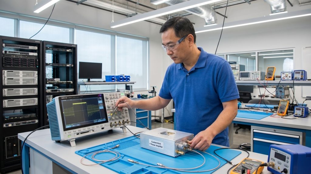
How do I know if my cooling is sufficient?
You can monitor the baseplate temperature of the amplifier during operation. If the temperature stabilizes well below the manufacturer’s maximum rating (typically 85°C) during a full-power stress test, your cooling system is adequate.
Can I customize the connectors on a standard amplifier module?
Yes. Most manufacturing partners offer OEM services to change connector types (e.g., SMA to N-type) or relocate interfaces to match your specific mechanical housing and cable routing.
What is the best way to handle high VSWR?
The most effective approach is to ensure the antenna and cables are properly matched to 50 ohms. If high VSWR is unavoidable, choose an amplifier with built-in reflected power protection to prevent the output stage from burning out.
Selecting Your Partner
Selecting the right RF power amplifier is a multi-dimensional task that requires a deep understanding of frequency, power, and thermal management. By systematically evaluating these specifications, you avoid the common pitfalls of hardware integration and ensure your system performs reliably in the field. At CorelixRF, our vision is to provide engineering-driven solutions that bridge the gap between standard platforms and custom requirements. We support our partners with factory-direct manufacturing and verified unit-level test data to ensure every project reaches its full potential. To discuss your specific technical requirements and find the ideal hardware for your application, contact us today.