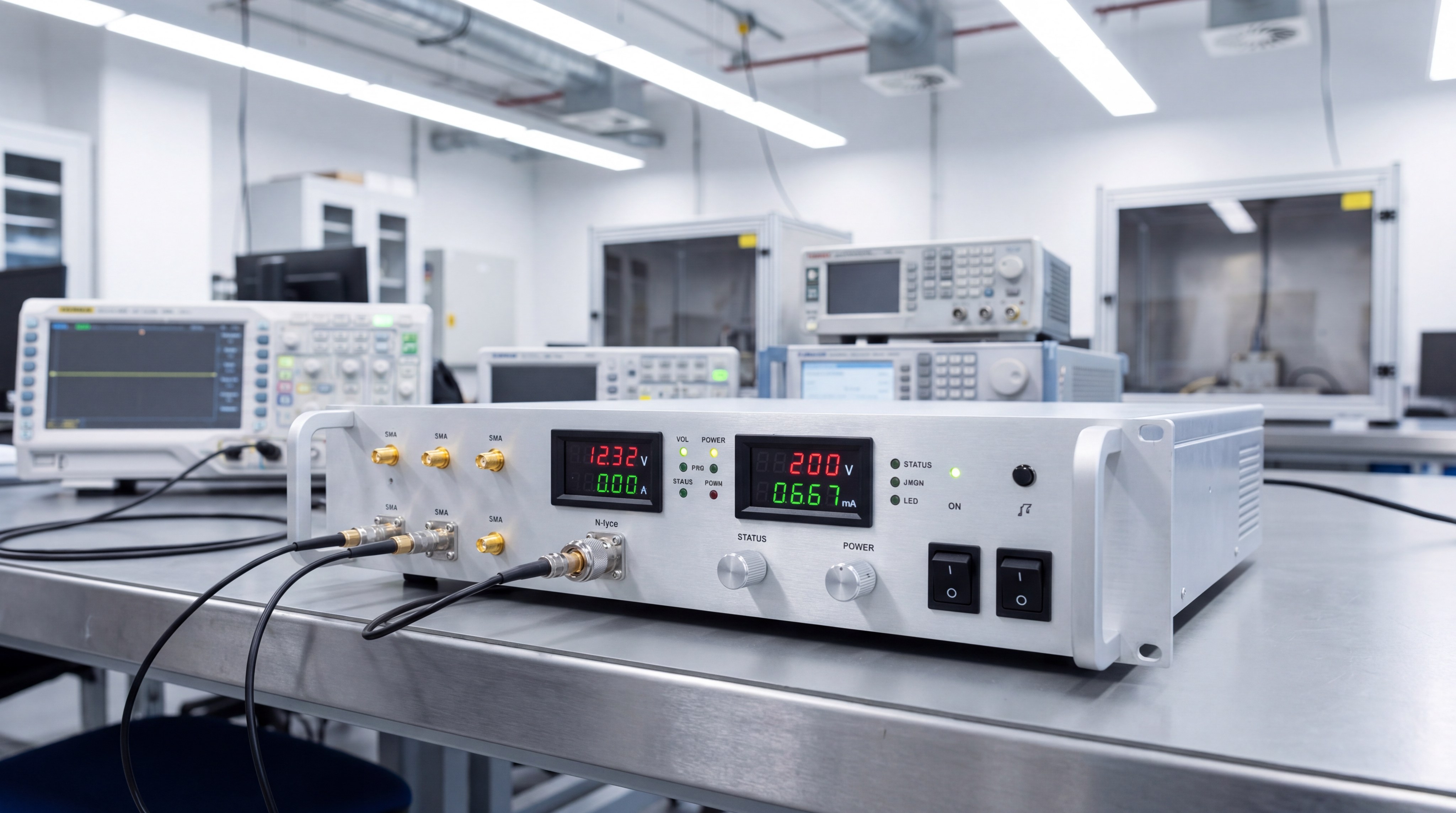
A pulse amplifier is a specialized electronic device designed to increase the magnitude of an input signal’s power, current, or voltage while preserving its original frequency and waveform characteristics. In complex RF environments, your standard continuous-wave hardware often lacks the peak power capability required for modern radar or high-intensity simulation. This limitation typically leads to signal degradation, insufficient range, or catastrophic thermal failure during high-duty cycles. By integrating a high-performance pulse amplifier, you can successfully drive demanding output devices without compromising the integrity of your mission-critical waveforms.
What defines a pulse amplifier in RF engineering?
An RF pulse amplifier is a component engineered to amplify intermittent bursts of energy rather than a steady stream. You use these systems to provide the high-peak-power output necessary for applications where waveform shape and rise/fall times are critical.
How does it differ from continuous wave amplifiers?
Standard continuous wave (CW) amplifiers prioritize steady-state stability over long durations. Conversely, pulsed systems are optimized for rapid response and extreme peak energy delivery within short intervals.
You need to understand these core differences:
- CW systems focus on thermal equilibrium during constant operation.
- Pulsed systems manage high thermal transients during brief bursts.
- Rise times are much faster in pulse-optimized hardware.
Here is the kicker:
A CW amplifier forced into pulse mode often suffers from severe signal distortion or overheating.
Why is pulse magnitude critical for output devices?
The magnitude of the output signal determines the effective range and sensitivity of your radar or communication link. By increasing the voltage or current peak, you ensure the signal can overcome path loss in long-distance environments.
Consider these primary categories:
- Voltage Amplifiers: Focused on increasing the waveform’s electrical potential.
- Current Amplifiers: Designed to boost the flow of charge to the load.
- Power Amplifiers: A comprehensive increase in total wattage output.
But that’s not all.
The choice between these depends entirely on the impedance requirements of your specific antenna or test load.
Key Takeaway: Selecting the correct pulse amplifier category ensures your output device receives the exact signal magnitude required for peak performance without damaging the hardware.
| Amplifier Type | Primary focus | Signal Interaction |
|---|---|---|
| Voltage | Voltage Magnitude | Output V > Input V |
| Current | Current Magnitude | Output I > Input I |
| Power | Total Wattage (V x I) | Significant Power Gain |
This table illustrates how different pulse amplifier designs target specific electrical parameters to meet varied engineering goals.
How is pulse power classified by circuit design?
The classification of a pulse amplifier is determined by its conduction angle and the way it handles signal cycles. Designers categorize these units into specific classes, ranging from Class A to Class C for analog waveforms, or Classes D through F for digital switching.
Why are classes A through C common in RF applications?
These classes provide a predictable roadmap for balancing power efficiency against signal distortion. In the RF world, you choose a class based on how much of the signal cycle the transistor actually amplifies.
Common analog traits include:
- Predictable linearity across the operating band.
- Established thermal management protocols for each class.
- Compatibility with various modulation schemes.
But wait, there’s more.
The conduction angle directly dictates whether you prioritize a clean signal or high energy savings.
Which classes support pulse width modulated signals?
For digital or Pulse Width Modulated (PWM) signals, you typically move into high-efficiency switching classes like Class D or E. These designs are ideal for applications where battery life or heat reduction is the primary concern.
Engineering teams usually look at:
- Linear Classes: Best for radar and complex analog pulses.
- Switching Classes: Optimal for high-efficiency digital transmission.
- Hybrid Classes: Specialized AB designs for modulated waves.
Here is the deal:
Selecting a switching class for an analog pulse can result in unusable output due to high-frequency noise.
Key Takeaway: Understanding the classification of your pulse amplifier allows you to match the circuit design to your signal’s specific linearity and efficiency requirements.
| Design Category | Common Classes | Target Signal Type |
|---|---|---|
| Linear | A, B, AB, C | Sine Waves, Radar Pulses |
| Switching | D, E, F | PWM, Digital Signals |
| Hybrid | Specialized AB | Complex Modulated Waves |
This data highlights the clear distinction between analog-centric designs and high-efficiency digital switching architectures.
How does a Class A pulse amplifier operate?
A Class A pulse amplifier operates by using a single active element to conduct the entire 360-degree cycle of the input signal. This constant conduction ensures the highest possible linearity, making it a favorite for lab-grade testing environments.
Why is single-transistor design used for analog?
The single-transistor approach eliminates the need for signal “hand-offs” between different components. You benefit from a smooth, continuous amplification process that minimizes harmonic distortion.
The advantages include:
- Maximum fidelity for the original waveform shape.
- Lowest possible phase noise in the output.
- Simple circuit architecture for easier maintenance.
But that’s not all.
Because the transistor is always active, the signal remains perfectly consistent throughout the pulse duration.
What causes the low efficiency in Class A units?
The primary drawback of this design is that the transistor consumes power even when no input signal is present. This results in significant heat generation and an efficiency rating that rarely exceeds 25% to 50%.
Typical thermal challenges involve:
- High idle current consumption.
- Requirement for massive heat sinks or active cooling.
- Potential for thermal drift during long pulses.
Here is the kicker:
While it is the most linear option, you pay for that precision with significantly higher power costs.
Key Takeaway: Class A pulse amplifier systems are the gold standard for linearity but require robust cooling solutions to handle their inherent inefficiencies.
| Configuration | Efficiency | Thermal Impact |
|---|---|---|
| Standard Class A | ~25% | Very High |
| Transformer-Coupled | Up to 50% | Moderate to High |
| Direct Drive | < 20% | Critical |
The table above demonstrates the significant thermal trade-off required when prioritizing the extreme linearity of Class A designs.
Why choose Class B for high-efficiency pulse needs?
You choose a Class B pulse amplifier when you need to significantly reduce heat and improve efficiency for high-power bursts. This design uses two complementary transistors, each handling exactly half of the waveform cycle to minimize idle power waste.
How do complementary transistors manage waveforms?
In a Class B setup, one transistor conducts the positive half of the pulse while the other handles the negative half. By only being “on” when needed, these components stay much cooler than their Class A counterparts.
The operational benefits are clear:
- Efficiency levels can reach up to 78%.
- Reduced power draw from the system supply.
- Smaller physical footprint due to lower cooling needs.
But that’s not all.
This push-pull configuration makes Class B ideal for portable or battery-operated RF equipment.
What causes the crossover distortion in these systems?
Distortion occurs at the “zero-crossing” point where the signal passes from one transistor to the other. If the timing isn’t perfect, you will see a small gap or glitch in the pulse shape.
Common issues include:
- Loss of signal fidelity during the transition.
- Increased harmonics at the output stage.
- Difficulty maintaining linearity for complex waveforms.
Make no mistake:
Crossover distortion is the main reason engineers often look toward hybrid designs for high-fidelity needs.
Key Takeaway: Class B systems offer excellent efficiency for pulse applications but require careful management of crossover distortion to protect signal integrity.
| Feature | Class B Performance | B2B Application |
|---|---|---|
| Efficiency | High (Up to 78%) | Portable RF Gear |
| Heat Dissipation | Low | Compact Enclosures |
| Linearity | Moderate | FM/Transistor Radios |
This analysis confirms that Class B is the preferred choice when thermal efficiency outweighs the need for absolute linear perfection.
Is Class AB the optimal balance for pulse power?
The Class AB pulse amplifier is widely considered the industry standard because it blends the linearity of Class A with the efficiency of Class B. It achieves this by allowing both transistors to conduct slightly more than 180 degrees, effectively smoothing the transition.
How does it resolve Class A and B limitations?
By maintaining a small “idle” current, Class AB ensures that the transistors are never fully off. This prevents the crossover distortion seen in Class B while remaining much more efficient than Class A.
Key design advantages:
- Elimination of zero-crossing glitches.
- High-fidelity reproduction of high-frequency pulses.
- Substantially lower heat generation than Class A.
But that’s not all.
Most modern radar systems rely on this class to maintain signal purity at high peak power levels.
What role do diodes play in pulse response?
Diodes are integrated into the biasing circuit to provide a stable reference voltage for the transistors. This ensures the amplifier responds instantly to the input pulse without any lag or startup distortion.
Typical stabilizing components include:
- Resistors for precise bias current control.
- Diodes to compensate for temperature fluctuations.
- Capacitors for signal decoupling and stability.
Here is the kicker:
Proper diode biasing is what allows these units to stay stable even in fluctuating ambient temperatures.
Key Takeaway: Class AB pulse amplifier hardware provides the most reliable performance for high-fidelity RF pulses by successfully mitigating distortion and heat.
| Parameter | Class AB Benefit | Result |
|---|---|---|
| Conduction Angle | > 180 Degrees | Smooth Transitions |
| Idle Current | Low/Controlled | High Stability |
| Linearity | High | Reliable Lab Data |
The table summarizes why Class AB is the preferred balanced architecture for professional-grade RF signal amplification.
When is Class C necessary for high-frequency RF?
You deploy a Class C pulse amplifier when maximum efficiency is your only priority and signal distortion can be managed via external filtering. These units are highly specialized for RF oscillations and high-power radar transmitters where the output frequency is constant.
Why does a lower conduction angle save power?
In a Class C design, the active element conducts for less than 180 degrees—often only for a tiny fraction of the pulse peak. By staying off for most of the cycle, the transistor dissipates almost no power as heat.
Efficiency metrics include:
- Theoretical efficiency exceeding 80%.
- Ability to deliver massive peak power from small units.
- Minimal thermal stress on the internal die.
But that’s not all.
This design is the backbone of high-frequency broadcasting and microwave-link transmitters.
How does a tuned load filter the output?
Because the conduction angle is so small, the raw output of a Class C unit is extremely distorted. You must use a “tank circuit” or tuned load to filter out the unwanted harmonics and restore a clean sine wave.
The filtering process involves:
- Using LC circuits to resonate at the target frequency.
- Suppressing all frequencies outside the narrow band.
- Converting high-energy pulses into a clean RF carrier.
Here is the deal:
Without a precisely tuned load, a Class C amplifier is practically useless for any standard communication.
Key Takeaway: Class C pulse amplifier systems are the peak of efficiency for narrowband RF applications, provided you integrate robust output filtering.
| Capability | Class C Performance | Radar Benefit |
|---|---|---|
| Efficiency | 80%+ | Max Peak Power |
| Frequency | High/Microwave | Ka/X-Band Support |
| Distortion | High (Filtered) | Specialized RF Only |
This data illustrates that Class C is a high-performance, niche solution where efficiency is prioritized over broadband linearity.
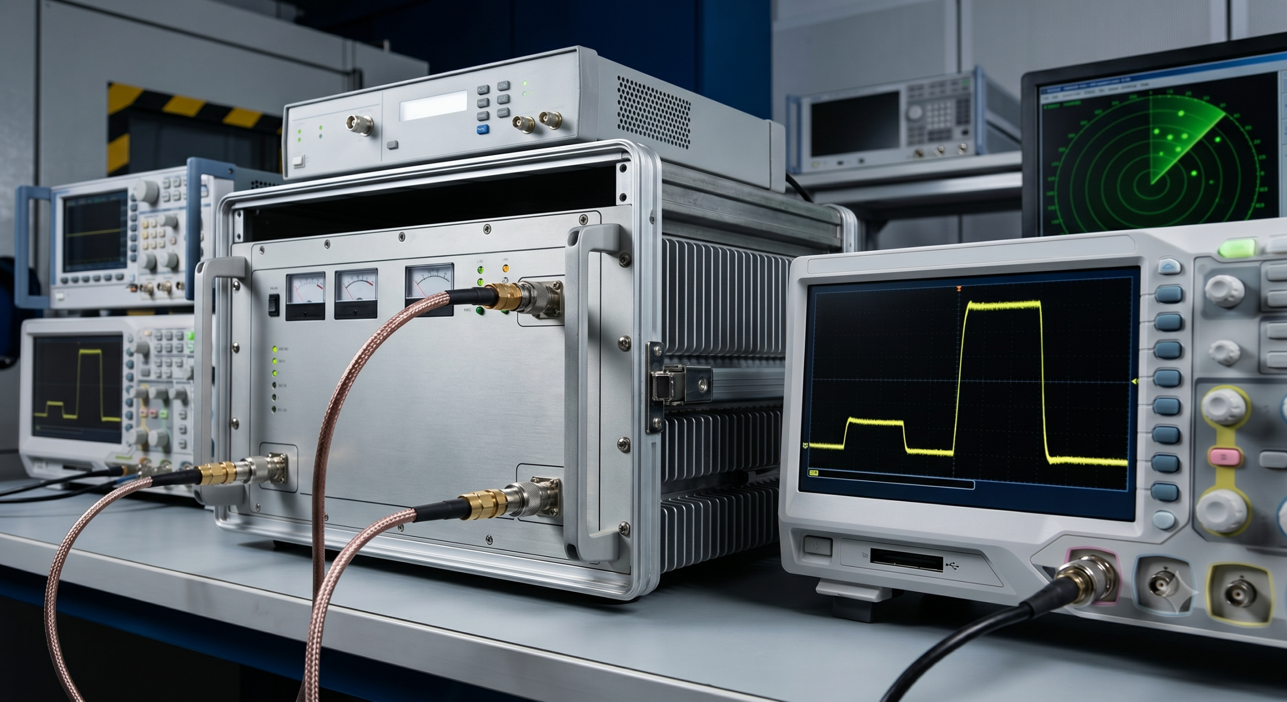
How does the internal working mechanism function?
The internal operation of a pulse amplifier involves a coordinated chain of events that starts with a pulse generator and ends at the final output stage. Every component must synchronize perfectly to ensure the amplified burst matches the timing of the original signal.
What is the role of the pulse source generator?
The pulse source acts as the “brain,” creating the low-voltage master signal that dictates the width and frequency of the output. This signal serves as the instruction set that the amplifier then reproduces at much higher energy levels.
The generator controls:
- Pulse Width: The duration of the high-energy burst.
- Pulse Repetition Frequency (PRF): How often the burst occurs.
- Duty Cycle: The ratio of “on” time to “off” time.
But that’s not all.
If the source generator drifts, the entire amplified output will lose its timing accuracy.
How does the controller regulate energy levels?
The internal controller monitors the input pulse and regulates the power supply to ensure the output stays within defined limits. It prevents the amplifier from “clipping” the signal or exceeding the thermal safety threshold of the transistors.
Control mechanisms include:
- Real-time voltage regulation.
- Thermal monitoring and automatic shutdown.
- Gain adjustment to maintain flatness across the pulse.
Here is the kicker:
Advanced digital controllers can even compensate for aging components to keep the pulse shape consistent over years of use.
Key Takeaway: The synergy between the pulse source and the internal controller is what defines the reliability and precision of a pulse amplifier system.
| Component | Function | Engineering Priority |
|---|---|---|
| Pulse Generator | Signal Origin | Timing/Width Accuracy |
| Controller | Power Regulation | Range Enforcement |
| Output Stage | Final Drive | Peak Magnitude |
The table breaks down the internal architecture, showing how each stage contributes to the final high-power output pulse.
What are the key applications for pulsed systems?
A pulse amplifier is essential in any sector where detection, simulation, or immunity testing requires high energy in short durations. You will find these units powering everything from aircraft radar to laboratory electromagnetic compatibility (EMC) setups.
How are pulse units used in radar and SATCOM?
Radar systems require short, intense bursts of RF energy to bounce off distant objects and return to a receiver. The pulse amplifier provides the “punch” needed for the signal to travel miles without losing its identifying shape.
Common radar uses:
- Air traffic control and weather monitoring.
- Defense-grade target acquisition.
- Satellite communication ground stations (SATCOM).
But that’s not all.
These units also support Unmanned Aerial Vehicle (UAV) links that must maintain a lock in high-interference environments.
Why is pulse power critical for EMC testing?
EMC testing involves bombarding a device with high-power pulses to see if it malfunctions under electromagnetic stress. You use these amplifiers to simulate lightning strikes or sudden interference from nearby high-power electronics.
Laboratory requirements include:
- High repeatability of every pulse burst.
- Wide frequency coverage for different standards.
- ISO 9001 certified reliability for official certification tests.
Make no mistake:
Without high-peak pulse power, you cannot effectively validate a product’s immunity to real-world electromagnetic threats.
Key Takeaway: From defending national airspace to ensuring consumer electronics safety, pulse amplifier technology is a fundamental tool for modern high-frequency engineering.
| Sector | Application | Required Capability |
|---|---|---|
| Defense | Radar / Counter-UAS | High Peak Power |
| Aerospace | SATCOM | Frequency Stability |
| Laboratory | EMC Testing | Pulse Consistency |
This comparison highlights the diverse environments where pulsed RF power is a non-negotiable requirement for operational success.
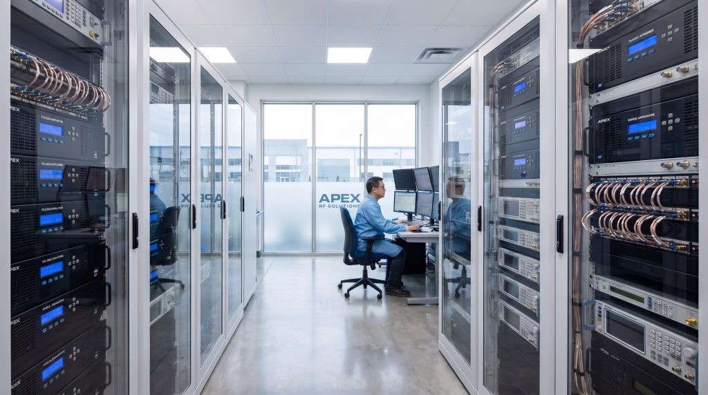
How to select between standard and custom platforms?
When you evaluate a pulse amplifier, you must decide if a standard broadband module or a custom-engineered system is right for your project. Standard platforms offer faster entry for common frequencies, while custom solutions handle specific microwave or millimeter-wave needs.
When do requirements exceed standard coverage?
If your project operates in the 18 GHz to 110 GHz range, standard platforms may lack the gain flatness or mechanical fit you require. Custom engineering is often necessary for non-standard bands or high-power multi-kW systems.
You might need a custom path for:
- Integration with specific SDR signal modules.
- Non-standard connector types (SMA, K-type, N-type).
- Unique cooling constraints (liquid-cooled or conduction-cooled).
But that’s not all.
High-frequency projects above 40 GHz almost always require a dedicated engineering review to ensure feasibility.
How does engineering review mitigate risk?
A formal engineering review ensures that every parameter—from frequency range to VSWR protection—matches your real-world operating conditions. This process prevents costly integration errors and ensures the unit arrives with validated test data.
The review steps typically include:
- Analyzing the target duty cycle and pulse width.
- Matching supply voltage to existing site power.
- Confirming gain and power flatness across the operating band.
Here is the kicker:
A 48-hour engineering review can save you months of troubleshooting during the final system integration phase.
Key Takeaway: Choosing between standard and custom pulse amplifier platforms depends on your frequency range and the complexity of your mechanical integration needs.
| Selection Path | Best For | Typical Range |
|---|---|---|
| Standard | Fast Entry / UAV / Comm | 30 MHz – 6 GHz |
| Custom | Project-Specific / OEM | 9 kHz – 40 GHz+ |
| Advanced | High Frequency / Radar | 18 GHz – 110 GHz |
This selection guide helps you identify the fastest and most reliable path to obtaining the RF hardware your project demands.
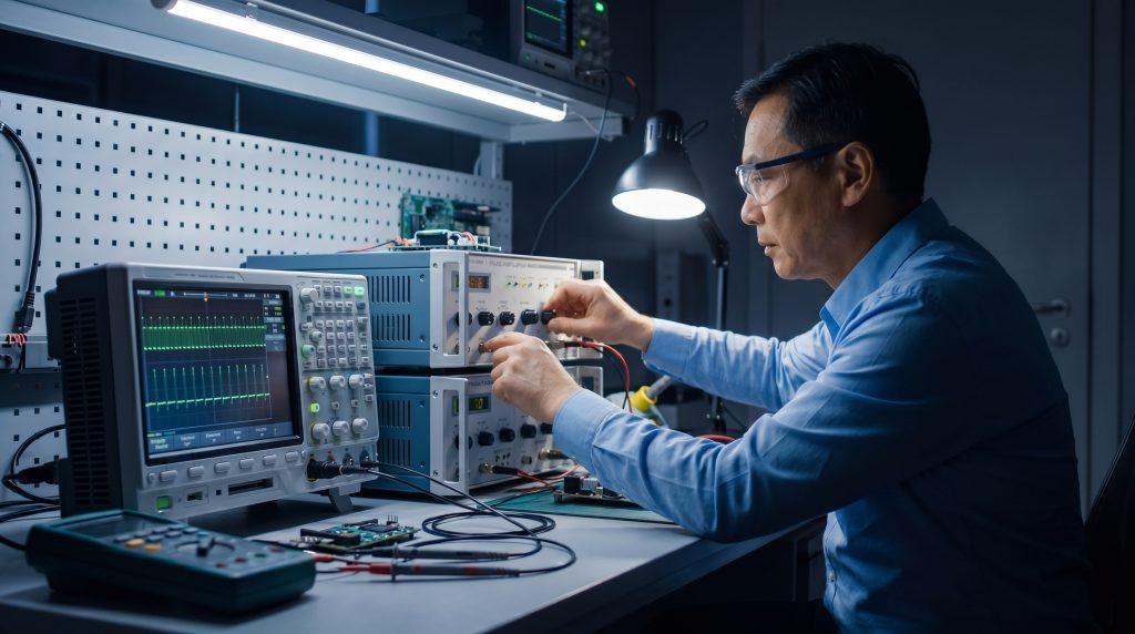
How do you validate pulse amplifier performance?
Validation is the final step where you confirm that your pulse amplifier meets every specification listed on its datasheet. For B2B buyers, this involves reviewing unit-level test data to ensure the hardware is ready for long-term deployment in the field.
Why is unit-level test data vital for buyers?
Unlike consumer-grade gear, professional RF amplifiers should never be integrated without individual test reports. You need to see the actual gain, peak power, and harmonics of the specific unit you purchased.
Verified data ensures:
- The unit meets VSWR protection standards.
- Power output is consistent across the entire band.
- Compliance with ISO 9001 and RoHS requirements.
But that’s not all.
Having this data on hand simplifies the troubleshooting process if your overall system performance dips during testing.
What parameters ensure long-term reliability?
Beyond raw power, you must evaluate the amplifier’s thermal dissipation efficiency and protection against load mismatches. A reliable unit will feature automatic shutdown protocols for over-temperature or high reflected power conditions.
Monitor these key metrics:
- Gain Flatness: Ensuring the pulse energy stays level.
- Harmonic Suppression: Keeping the signal clean.
- Cooling Performance: Managing the heat under heavy duty cycles.
Here is the deal:
Long-term reliability is built into the design stage, not added as an afterthought during final testing.
Key Takeaway: Rigorous unit-level validation and documented test data are the only ways to guarantee your pulse amplifier will perform reliably in mission-critical applications.
| Step | Action | Expected Outcome |
|---|---|---|
| 1. Specs | Submit Frequency/Power | Initial Feasibility |
| 2. Review | Engineering Consultation | Platform Matching |
| 3. Delivery | Unit-Level RF Testing | Validated Integration |
This sequence outlines the standard B2B workflow for moving from an initial RF requirement to a fully validated hardware delivery.
*
Selecting the right pulse amplification technology requires a deep understanding of circuit classes, thermal management, and application-specific duty cycles. At our core, we believe that providing factory-direct engineering support is the only way to ensure B2B buyers receive hardware that actually works in real-world electromagnetic environments. From standard broadband modules to custom multi-kW microwave systems, every product we deliver is backed by over 30 years of RF experience and verified unit-level testing. To begin your project review or to request a detailed datasheet, contact us today to speak with a senior RF engineer.
Pulse Amplifier FAQ
Can I use a pulse amplifier for continuous wave signals?
Generally, no. Most pulse-optimized amplifiers have duty cycle limitations and thermal designs that will lead to catastrophic failure if operated in continuous mode for extended periods.
What’s the best class for a radar pulse application?
Class AB is typically the best choice. It provides the necessary balance of high linearity to maintain the pulse shape and enough efficiency to handle high peak power without excessive heat.
Can I customize the connector types on a standard platform?
Yes, most manufacturers offer connector customization (such as SMA, N-type, or K-type) as part of a custom engineering review to match your existing RF chain.
How do I know if I need a custom engineering review?
You should seek a review if your frequency requirements exceed 6 GHz, if you need multi-kW peak power, or if your mechanical integration space is strictly limited.
Is unit-level test data always included with every shipment?
In professional B2B RF manufacturing, unit-level test data should be standard. It is critical for validating that each specific piece of hardware meets your integration requirements.
Engineering next step
Turn this pulse amplifier selection review into a project-ready RF path
If this article matches your design or procurement stage, continue from the technical notes to CorelixRF product platforms, documentation support, and the RF inquiry form. Sharing frequency range, output power, waveform, load condition, interface, and documentation needs helps engineering review the right path faster.