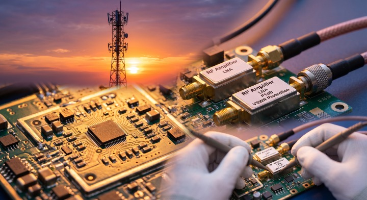
The important RF amplifier specifications are defined by technical parameters—such as gain, bandwidth, linearity, and noise figure—that determine how effectively a device boosts a signal while maintaining its integrity. Selecting the wrong hardware often leads to signal clipping, excessive heat generation, and complete system failure. Imagine deploying an expensive communication link only to find that the amplifier saturates too early or the noise masks the very signal you are trying to capture. Mastering these technical parameters ensures you make informed decisions that guarantee long-term reliability. High-performance RF Amplifiers provide the essential foundation for these complex signal chains.
What is the primary purpose of RF amplifiers in communication?
The primary purpose of these devices is to increase the power level of a signal to overcome transmission losses or drive an antenna with sufficient strength. In modern systems, RF Amplifiers act as the bridge between low-power processing and high-power transmission.
Driving the Signal Chain
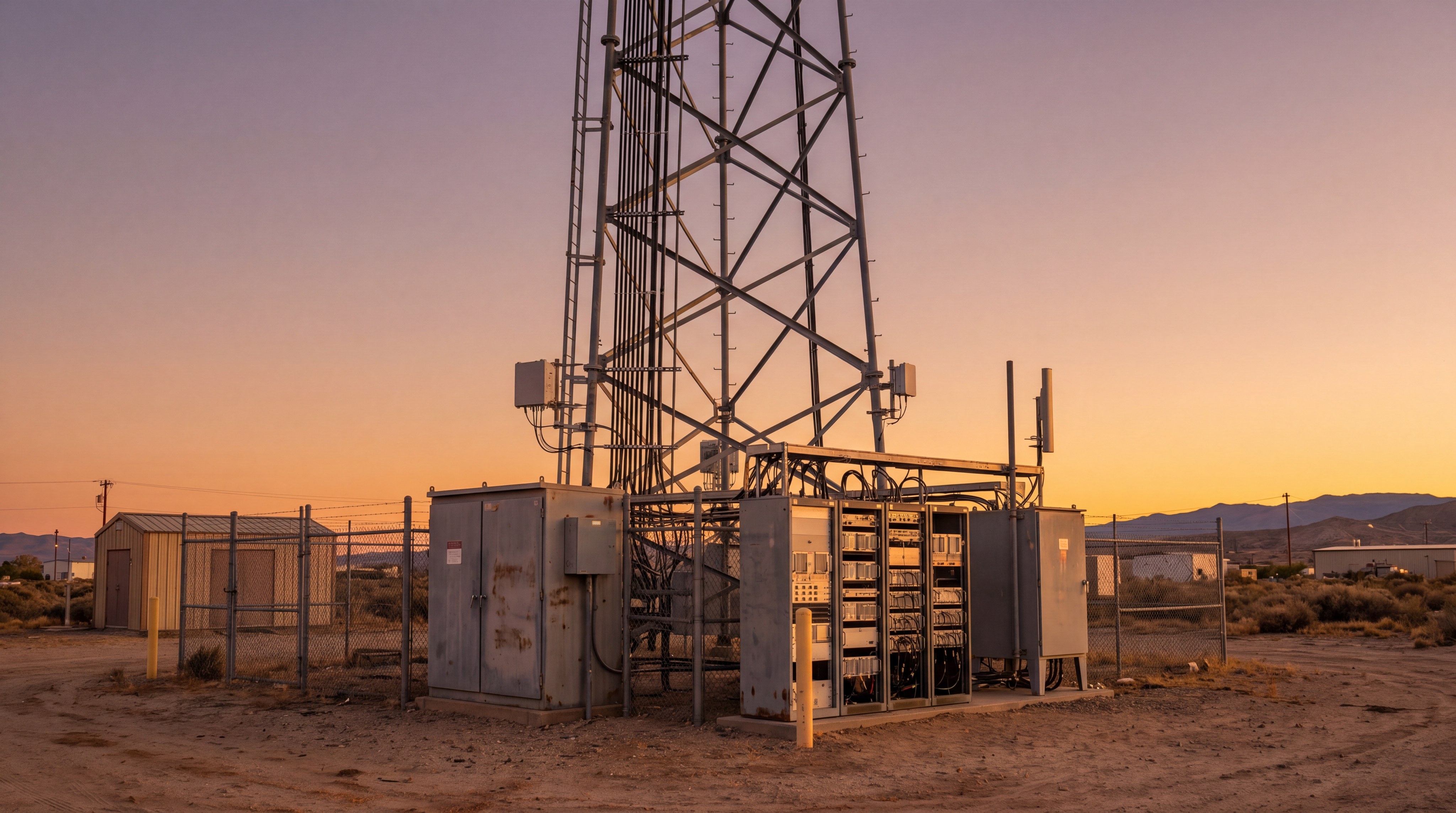
You must ensure that the signal reaches its destination without being buried by the noise floor of the medium. These components are strategically placed in the transmit chain to maximize range and coverage area.
- Boost Power: Overcomes path loss in terrestrial or satellite links.
- Signal Stabilization: Maintains signal levels across long cable runs.
- Impedance Matching: Provides a stable interface for the antenna.
But that’s not all. You can explore how RF Amplifiers are integrated into robust communication platforms to solve specific link budget challenges.
Key Takeaway: The primary role is power augmentation to ensure your signal maintains its integrity across the entire transmission path.
| Feature | Primary Function | Application Value |
|---|---|---|
| Power Gain | Signal Boost | Increases Range |
| Driver Stage | Link Prep | Drives Power Stages |
| SSPA Architecture | Stability | Long-term Reliability |
The following data compares how different power levels affect the overall system capability.
How does gain flatness affect your signal quality?
Gain flatness ensures that the level of amplification remains consistent across the entire operational frequency range of the device. If RF Amplifiers exhibit high variation in gain, your signal calibration will become a nightmare for wideband applications.
Maintaining Wideband Integrity
When you sweep across a broad spectrum, you need the output to be predictable. Significant gain ripples can cause digital bit errors in complex modulation schemes like OFDM.
- Predictability: Ensures consistent power across all sub-carriers.
- Calibration Ease: Simplices the software compensation needed for the system.
- Signal Purity: Prevents unwanted spectral regrowth due to gain spikes.
Here’s the kicker: even a 2 dB variance can ruin the performance of a high-speed data link. You should always check the datasheet for the maximum deviation over the full bandwidth.
Key Takeaway: High gain flatness is essential for maintaining uniform performance in multi-frequency and broadband systems.
| Spec | Target Value | System Impact |
|---|---|---|
| Flatness | +/- 1.0 dB | High Stability |
| Ripple | Minimal | Low Distortion |
| Slope | Linear | Easy Compensation |
Consider this breakdown of how gain variance impacts different modulation types.
Why is 1dB compression point critical for your system?
The 1dB compression point (P1dB) defines the operational limit where the amplifier’s gain drops by 1 dB from its linear value. For RF Amplifiers, this metric is the practical boundary for clean, linear data transmission.
Operating within Linear Limits
You generally want to operate your system a few decibels below the P1dB to avoid signal clipping. Pushing hardware into compression results in severe harmonic distortion and loss of data integrity.
- Linear Region: The “safe zone” where output increases proportionally with input.
- Compression Knee: Where the amplifier begins to lose efficiency and gain.
- Headroom: The safety margin you maintain to prevent peak signal clipping.
Think about it this way: operating too close to P1dB is like redlining an engine. You can achieve more power with RF Amplifiers designed for higher linear thresholds.
Key Takeaway: P1dB is the most reliable indicator of an amplifier’s maximum useful linear output power.
| Parameter | Unit | Importance |
|---|---|---|
| P1dB | dBm | High (Linearity) |
| Psat | dBm | Medium (Saturation) |
| Back-off | dB | Critical (Safety) |
The table below illustrates the relationship between P1dB and signal saturation levels.
How do third-order intercept points define linearity?
The Third-Order Intercept Point (OIP3) is a theoretical metric used to predict how much intermodulation distortion your device will generate. High-linearity RF Amplifiers have OIP3 values significantly higher than their P1dB to accommodate complex signals.
Minimizing Intermodulation Distortion
When you transmit multiple frequencies, they can mix inside the amplifier and create “ghost” signals. These spurious products can interfere with adjacent channels and violate regulatory masks.
- IMD3 Products: Unwanted signals that appear close to your fundamental frequency.
- OIP3 Margin: The gap between operating power and the intercept point.
- Spectral Purity: A higher OIP3 ensures a cleaner spectrum for your neighboring users.
Let’s dig deeper. The OIP3 provides a single, comparable number that helps you evaluate how well the hardware handles multi-tone waveforms.
Key Takeaway: A higher OIP3 indicates superior linearity and better performance for advanced data modulation schemes.
| Metric | Ideal Ratio | Result |
|---|---|---|
| OIP3 vs P1dB | +10 dB | Low Distortion |
| IMD3 Level | -40 dBc | High Purity |
| Linearity | Constant | Clear Signal |
Review the following analysis of linearity requirements for modern digital standards.
What role does the noise figure play in receiver sensitivity?
Noise figure (NF) measures the amount of noise the hardware adds to the signal as it passes through the system. For RF Amplifiers used in receiver front ends, a low noise figure is the most critical factor for detecting weak signals.
Maximizing the Signal-to-Noise Ratio
You must keep the internal noise floor as low as possible to maintain a high SNR. Once a signal is buried in noise, no amount of subsequent amplification can recover the original data.
- Sensitivity: Determines the minimum signal power the system can process.
- Cascaded Noise: The first stage of amplification dominates the total system noise.
- Receiver Range: Lower NF directly translates to longer detection distances.
But that’s not all. You can learn more about how we prioritize low-noise designs in our RF Amplifiers to support sensitive laboratory and field measurements.
Key Takeaway: Noise figure is the primary specification for determining how well your system can hear weak transmissions.
| Component | Target NF | Typical Use |
|---|---|---|
| LNA Stage | < 1.5 dB | Satellite/Radar |
| Driver Amp | 3.0 – 5.0 dB | General Purpose |
| Power Amp | > 7.0 dB | Transmit Path |
This comparison shows how NF affects the total range of your communication link.
Why should you care about input and output VSWR?
VSWR (Voltage Standing Wave Ratio) measures the efficiency of power transfer and indicates how much energy is reflected back into the device. Managing VSWR in RF Amplifiers is vital for protecting sensitive internal transistors from catastrophic failure.
Preventing Reflected Power Damage
When you have a mismatch between the amplifier and the load, power is reflected as heat. Excessive reflected power can cause internal arcing and permanently damage your expensive hardware.
- Match Efficiency: A lower VSWR means more power reaches your antenna.
- System Protection: Reduces the thermal stress on the output stage.
- Load Stability: Ensures the amplifier does not oscillate when connected to complex loads.
Here’s the secret: many modern systems include automatic VSWR protection that scales back power if a bad match is detected.
Key Takeaway: Low VSWR ensures maximum power transfer and provides a critical layer of hardware protection.
| VSWR Ratio | Reflected Power | Match Quality |
|---|---|---|
| 1.2:1 | 0.8% | Excellent |
| 1.5:1 | 4.0% | Very Good |
| 2.0:1 | 11.1% | Acceptable |
The following table highlights the risks associated with high reflected power levels.
How does power efficiency impact your thermal management?
Power added efficiency (PAE) tells you what percentage of DC power is successfully converted into usable RF output. For high-power RF Amplifiers, efficiency is the primary driver of your cooling and power supply requirements.
Reducing Heat and Operating Costs
You must dissipate every watt of DC power that is not converted into RF. Low-efficiency amplifiers generate massive amounts of heat, requiring large heatsinks and loud fans that add weight to your system.
- Thermal Load: Lower efficiency equals more heat to manage.
- Battery Life: Critical for portable, airborne, and drone-based systems.
- SWaP Optimization: High efficiency allows for smaller, lighter enclosures.
By utilizing an RF Amplifiers selection tool, you can find hardware that balances power output with thermal constraints.
Key Takeaway: High PAE reduces the physical footprint of your system and lowers long-term operational costs.
| Class | Typical PAE | Main Application |
|---|---|---|
| Class A | 20% | Pure Linearity |
| Class AB | 45% | Communications |
| Class D/E/F | > 60% | High Power/Pulse |
See the analysis below for thermal dissipation requirements based on amplifier efficiency.
What are the benefits of GaN technology in RF amplifiers?
Gallium Nitride (GaN) technology has revolutionized the industry by providing significantly higher power density and bandwidth than silicon. These RF Amplifiers allow you to build smaller systems that put out significantly more power.
Advancing with Modern Semiconductors
You benefit from GaN’s ability to operate at higher voltages and temperatures compared to LDMOS or GaAs. This makes the technology ideal for mission-critical applications that require ruggedized performance.
- Power Density: More watts per square millimeter of chip area.
- Bandwidth: Superior performance across multi-octave frequency ranges.
- Durability: High breakdown voltage improves survivability against surges.
Think about it this way: switching to GaN is like upgrading from a heavy V8 engine to a lightweight, turbocharged performance motor.
Key Takeaway: GaN technology provides the best combination of power, size, and frequency coverage available today.
| Technology | Bandwidth | Power Density | Thermal |
|---|---|---|---|
| GaN | Wide | Very High | Excellent |
| LDMOS | Narrow | High | Good |
| GaAs | Medium | Low | Fair |
The following data compares GaN performance across various frequency bands.
How to choose the right frequency range for your needs?
The frequency range defines the operational spectrum where the hardware is guaranteed to meet its performance specifications. You must select RF Amplifiers that cover your target band while maintaining sufficient gain and power at the edges.
Matching Bandwidth to Application
When you choose a frequency range, you should consider whether you need a narrowband or broadband solution. Narrowband units often provide better efficiency, while broadband units offer maximum flexibility for testing.
- Center Frequency: The primary frequency where the unit is optimized.
- Operating Bandwidth: The full range where the device remains stable.
- Frequency Guard-bands: Allow extra margin for signal drift or wider modulation.
You can browse our full catalog of RF Amplifiers to find the exact frequency coverage required for your specific mission.
Key Takeaway: Always select a frequency range that provides 10-20% headroom beyond your actual operating bandwidth.
| Band Type | Coverage | Advantage |
|---|---|---|
| Narrowband | < 10% | Max Efficiency |
| Octave | 2:1 Ratio | Versatility |
| Ultra-Wide | > 10 Octaves | Multi-Mission |
Consider this summary of standard frequency bands used in commercial and defense sectors.
Which packaging style fits your integration requirements?
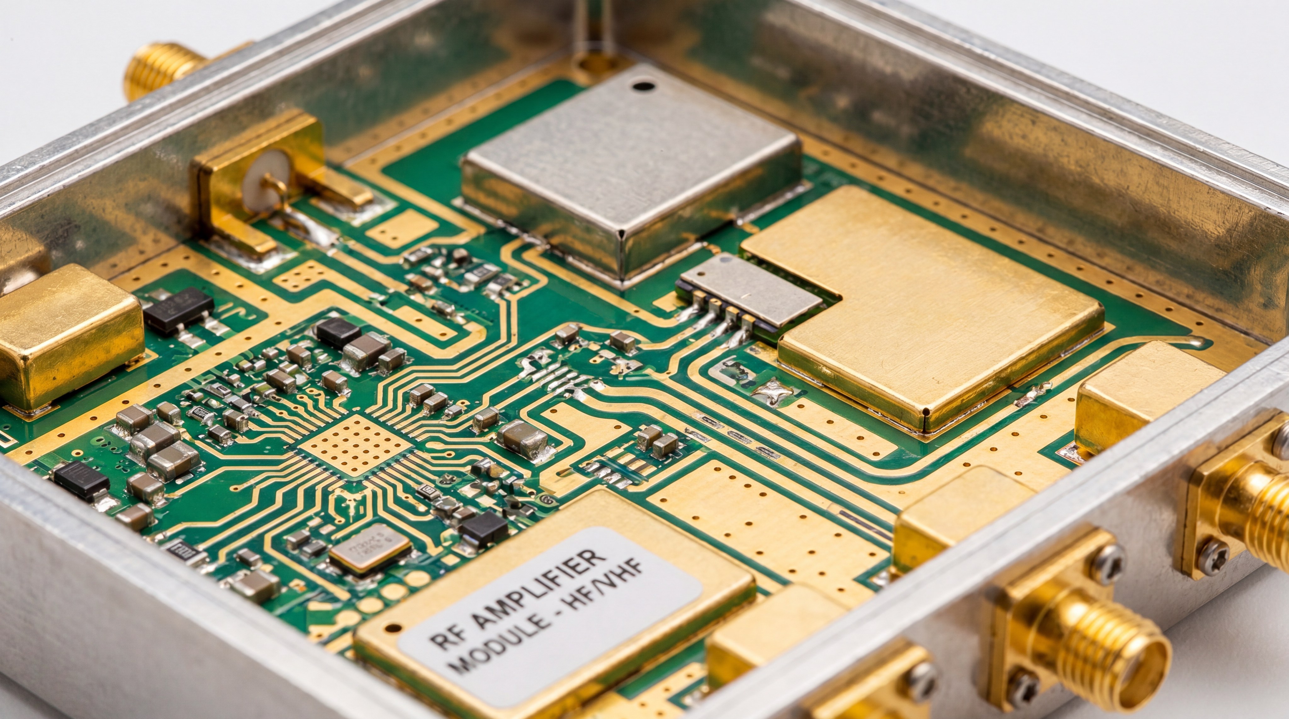
The packaging style determines the physical footprint, mounting method, and cooling strategy for your hardware. Whether you are integrating RF Amplifiers into a portable drone or a massive laboratory rack, the mechanical interface is non-negotiable.

Optimizing for Deployment Environments
You must choose between module-level, benchtop, or rack-mount configurations based on your available space and power infrastructure. Ruggedized aluminum housings are often preferred for field deployments where vibration and moisture are factors.
- Module SSPA: Compact and designed for direct integration into enclosures.
- Rack-Mount: Built for 19-inch cabinets in data centers or labs.
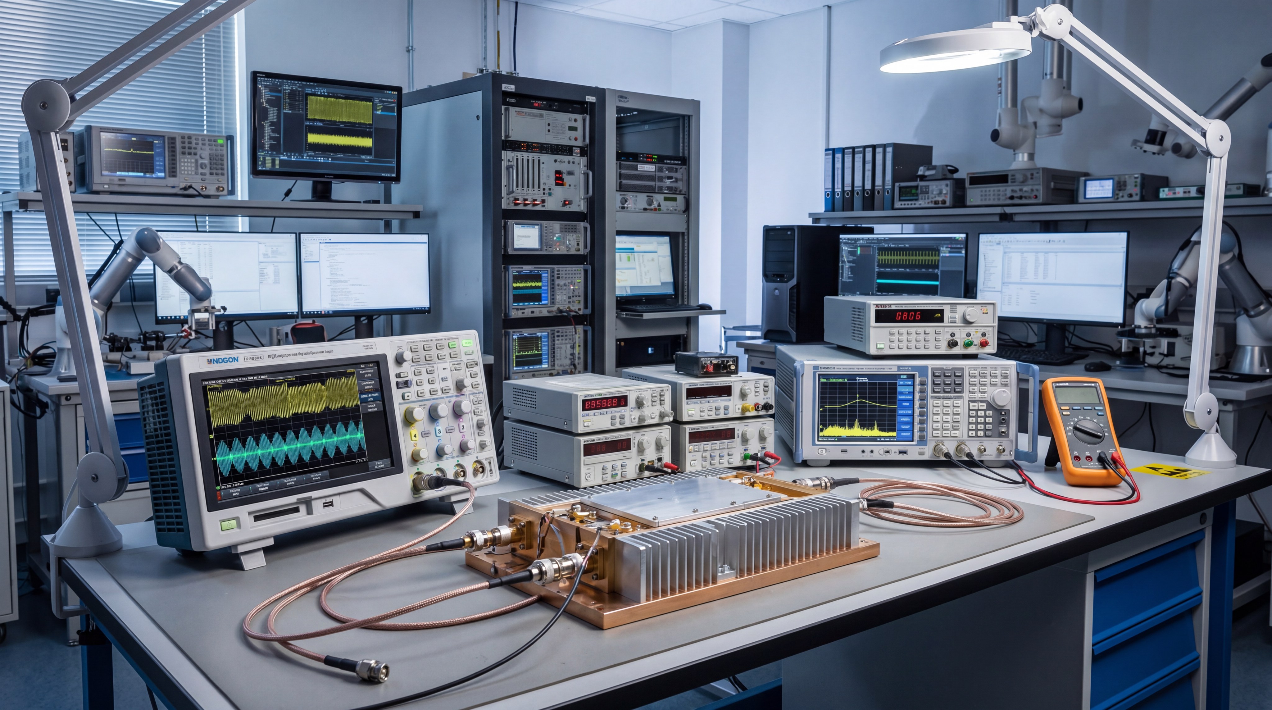
- Benchtop: Portable units with built-in displays and controls for R&D.
But that’s not all. The choice of connectors—such as SMA, N-type, or 2.92mm—is also determined by your frequency and power levels.
Key Takeaway: Mechanical specs must be matched early in the design phase to avoid costly chassis redesigns later.
| Style | Cooling | Weight | Use Case |
|---|---|---|---|
| Module | Conduction | Light | Drone/UAV |
| Benchtop | Forced Air | Medium | Lab Testing |
| Rack-mount | Liquid/Fan | Heavy | High Power |
The final analysis below reviews how packaging influences system-level thermal performance.
Frequently Asked Questions
Can I use a broadband amplifier for a narrowband signal?
Yes. While a broadband unit is versatile, you may sacrifice some efficiency compared to a dedicated narrowband amplifier tuned for a specific frequency.
What’s the best way to prevent amplifier overheating?
Proper heatsinking is mandatory. You should always ensure the baseplate is flush against a thermal mass and monitor the internal temperature sensors if available.
How do I know if I need a Low Noise Amplifier (LNA)?
If you are receiving. LNAs are essential at the very beginning of a receiver chain to boost weak incoming signals without adding excessive noise.
Can I run two amplifiers in series to get more gain?
Yes, but be careful. You must ensure the output of the first stage does not overdrive the input of the second stage, which could cause damage.
What happens if I operate the unit with no antenna connected?
This is dangerous. Without a load, all power is reflected back into the amplifier (high VSWR), which can destroy the output transistors instantly.
Conclusion and Final Recommendations
Selecting high-performance RF hardware requires a balanced evaluation of electrical, thermal, and mechanical constraints. By mastering specifications like P1dB for linearity, VSWR for safety, and gain flatness for signal quality, you can build systems that withstand real-world challenges. This article has detailed the core parameters necessary to avoid signal distortion, hardware failure, and redesign delays. If you are ready to transition from technical specifications to physical hardware, contact us today to discuss your project requirements with an expert engineer.
CorelixRF is dedicated to advancing the future of high-frequency power platforms through factory-direct innovation and verified engineering excellence.