
Selecting a peerless Low Noise Amplifier requires a meticulous evaluation of noise figure, gain, and linearity to maximize the sensitivity of your receiver system. You often encounter situations where weak incoming signals are buried under the thermal noise floor, making it impossible to extract clean data. When noise masks your critical information, system reliability plummets and error rates soar. A high-performance Low Noise Amplifier solves this by providing the necessary boost at the front end while contributing negligible noise of its own.
What is a Low Noise Amplifier and why does it matter?
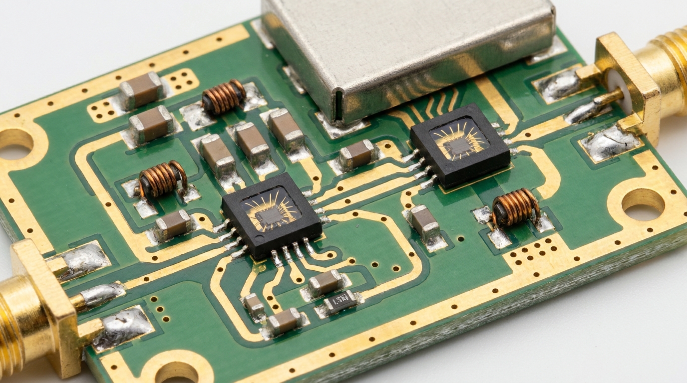
A Low Noise Amplifier is the primary active component in a radio receiver circuit designed to amplify extremely weak signals without significantly degrading their signal-to-noise ratio. Because it is positioned at the very start of the RF chain, its performance determines the baseline sensitivity for the entire system. Think of it as the gatekeeper of your signal quality, ensuring that subsequent stages receive a clear, strong input.
Does it define system sensitivity?
Yes, the sensitivity of your receiver is almost entirely dictated by the noise performance of the first Low Noise Amplifier in the signal path. If the LNA adds too much noise, the weak signals you are trying to capture will be lost forever in the background static.
But here is the kicker:
- It establishes the minimum detectable signal level.
- It protects signal integrity for downstream components.
- It reduces the impact of noise from later, noisier stages.
Where should you place it?
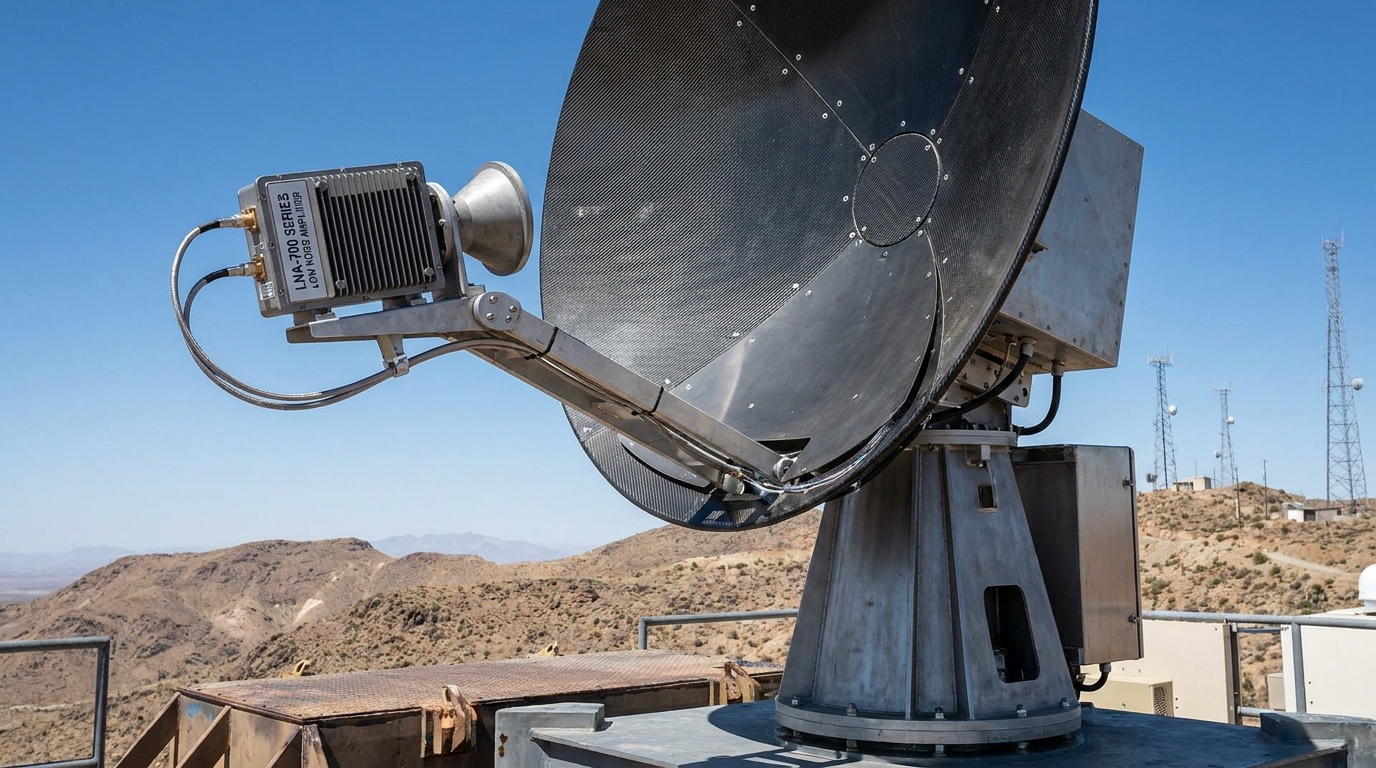
You must place the Low Noise Amplifier as close to the antenna as possible to minimize losses from cables and connectors. Any loss incurred before the LNA adds directly to the system noise figure, which is why integrated antenna-amplifier systems are highly effective.
Think about it:
- Cable loss before the LNA cannot be recovered.
- Proper placement maximizes the effective gain.
- Remote mounting often requires weatherproof packaging.
Key Takeaway: The LNA is the most critical block for determining how well your system can hear weak signals in a crowded RF environment.
| Parameter | Impact on System | Priority |
|---|---|---|
| Sensitivity | High | Critical |
| Placement | Signal Integrity | Maximum |
| Integration | Complexity | High |
Let’s examine how the actual gain levels influence these results.
How do you evaluate the ideal LNA gain for your system?
Evaluating the ideal gain for a Low Noise Amplifier involves finding a balance where the signal is boosted enough to overcome the noise of the next stage without saturating the receiver. If you choose a gain that is too low, the noise from the mixer or ADC will dominate. Conversely, excessive gain can lead to distortion and intermodulation interference.
Is more gain always better?
No, excessive gain in a Low Noise Amplifier can actually degrade your system performance by reducing the overall dynamic range and causing compression. High gain makes the receiver more susceptible to strong interfering signals nearby.
Look at it this way:
- High gain improves the cascaded noise figure.
- Too much gain causes nonlinear distortion.
- Balanced gain protects the receiver’s front-end.
How does Friis’ formula apply?
Friis’ formula shows that the noise of the first stage is the most important, while the noise of subsequent stages is reduced by the gain of the Low Noise Amplifier. By providing sufficient gain, you effectively “mask” the noise of the rest of the receiver.
The best part?
- Gain reduces the “noise contribution” of the second stage.
- 15dB to 20dB is often the “sweet spot” for most systems.
- Precision matching ensures the gain is stable over temperature.
Key Takeaway: Selecting gain is an optimization task that protects the receiver from noise while maintaining headroom for strong signals.
| Gain Level | Noise Figure Benefit | Distortion Risk |
|---|---|---|
| Low (<10dB) | Minimal | Low |
| Moderate (15-20dB) | Optimal | Low |
| High (>25dB) | Diminishing | High |
Let’s analyze why the noise figure itself is the ultimate benchmark.
Why is the Noise Figure the most critical specification?
The Noise Figure (NF) is the most critical specification because it represents the exact amount of signal-to-noise ratio degradation caused by the Low Noise Amplifier. In simple terms, it tells you how much “noise” the amplifier adds to the signal it is processing. A lower NF means a cleaner signal, which is essential for long-range communications and sensitive radar systems.
What is the difference between Noise Factor and Noise Figure?
Noise Factor is the numerical ratio of the input SNR to the output SNR, while Noise Figure is that same value expressed in decibels (dB). For a Low Noise Amplifier, engineers always aim for a Noise Figure as close to 0 dB as physically possible.
Think about it:
- A 1dB NF means the amplifier adds very little noise.
- A 3dB NF means the noise power is doubled at the output.
- Precision measurement requires specialized lab equipment.
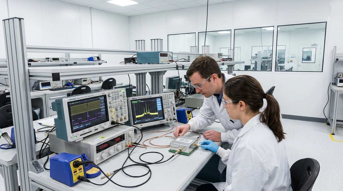
Can you achieve a sub-1dB NF?
Yes, modern semiconductor processes like GaN and pHEMT allow a Low Noise Amplifier to achieve Noise Figures well below 1.0 dB at microwave frequencies. These “ultra-low-noise” devices are the gold standard for satellite ground stations and deep-space telemetry.
Here is why it matters:
- Sub-1dB NF enables communication with distant satellites.
- It allows for smaller, more portable antenna designs.
- It provides a significant advantage in electronic warfare scenarios.
Key Takeaway: Every tenth of a decibel improved in the Noise Figure directly extends the operating range and reliability of your RF link.
| Noise Figure | Performance Class | Typical Application |
|---|---|---|
| < 0.8 dB | Ultra-Low Noise | SATCOM / Deep Space |
| 1.0 – 2.0 dB | High Performance | Radar / SIGINT |
| > 3.0 dB | Standard | Consumer Wireless |
Now, we must consider how linearity affects these sensitive signals.
How does linearity affect your signal processing?
Linearity determines how accurately a Low Noise Amplifier can process a signal without introducing unwanted frequencies or distortion. In environments with multiple strong signals, a non-linear amplifier will create “ghost” signals known as intermodulation products. If your LNA lacks high linearity, these artifacts will interfere with your primary data stream.
Why does IP3 matter?
The Third-Order Intercept Point (IP3) is a theoretical metric used to define the linearity of a Low Noise Amplifier before it becomes heavily distorted. A higher IP3 indicates that the amplifier can handle strong interfering signals without compromising the weak signal you are trying to receive.
The best part?
- High IP3 prevents “blocking” by nearby transmitters.
- It ensures clean spectrum output in multi-channel systems.
- It is a key indicator of overall design quality.
How do harmonics affect performance?
Non-linear behavior in a Low Noise Amplifier generates harmonics, which are multiples of the input frequency that can leak into other bands. This can cause your system to fail regulatory compliance or interfere with other sensitive on-board electronics.
Look at it this way:
- Filtering can remove harmonics but adds insertion loss.
- High linearity reduces the need for heavy output filtering.
- Linear LNAs maintain better signal constellations in digital MODEMs.
Key Takeaway: High linearity is essential for operating in “congested” RF environments where multiple signals compete for spectrum.
| Linearity Metric | Higher Value Result | System Benefit |
|---|---|---|
| OIP3 | Better interference rejection | Multi-signal stability |
| Harmonics | Lower spurious emissions | Regulatory compliance |
| Linearity | Better signal fidelity | Lower Bit Error Rate (BER) |
Next, we look at the physical limits of power handling.
What is the significance of the 1dB compression point?
The 1dB compression point (P1dB) is the input power level at which the gain of the Low Noise Amplifier drops by 1dB from its ideal linear value. It represents the upper limit of the amplifier’s linear operating range. Beyond this point, the LNA enters saturation, meaning it can no longer increase its output power linearly with the input.
How does P1dB relate to power handling?
The P1dB specification tells you the maximum signal strength your Low Noise Amplifier can handle before it starts distorting the signal waveform. This is vital if your receiver is located near high-power transmitters or radar pulse sources.
Think about it:
- A higher P1dB allows for better resilience against “jammer” signals.
- It defines the top end of the usable signal range.
- Exceeding P1dB significantly degrades the Noise Figure.
Is it different for CW vs pulsed signals?
Yes, a Low Noise Amplifier may behave differently under continuous wave (CW) conditions compared to high-power short pulses. Some LNAs are optimized for pulse survival, allowing them to withstand temporary high-power spikes without permanent damage.
But here is the kicker:
- Pulse-rated LNAs often have built-in limiters.
- CW P1dB is a more standard measure for comms.
- Peak power handling is critical for radar protection.
Key Takeaway: P1dB defines the “ceiling” of your signal environment; you must ensure your expected peak inputs stay below this level.
| Power Metric | Definition | Importance |
|---|---|---|
| P1dB | Linear power limit | High |
| Saturation (Psat) | Absolute max output | Moderate |
| Max Input Power | Damage threshold | Critical |
This leads directly into the concept of dynamic range.
How do you determine the required dynamic range?
You determine the required dynamic range for your Low Noise Amplifier by calculating the difference between the noise floor and the maximum signal level the system must handle. A wide dynamic range allows you to receive a faint signal even when a very strong signal is present in a nearby channel. Without sufficient range, the strong signal will “blind” the receiver to the weak one.
What is Spurious-Free Dynamic Range (SFDR)?
SFDR is a measure of the range between the smallest detectable signal and the point where intermodulation distortion products become visible. For a high-performance Low Noise Amplifier, a large SFDR is necessary to ensure that “phantom” signals don’t trigger false detections.
Look at it this way:
- High SFDR is essential for spectrum monitoring.
- It allows the LNA to work in environments with high “clutter.”
- It is the ultimate test of an LNA’s “cleanliness.”
Key Takeaway: Dynamic range defines the versatility of your LNA, allowing it to perform in both quiet and noisy RF environments.
| Range Type | Calculation | System Goal |
|---|---|---|
| Linear Range | P1dB – Noise Floor | Maximize total span |
| SFDR | IP3 – Noise Floor | Prevent false signals |
| Dynamic Range | Signal Max – Signal Min | Handle all signal levels |
Let’s explore why bandwidth consistency matters.
Why is gain flatness vital for wideband applications?
Gain flatness is vital for wideband applications because it ensures that the Low Noise Amplifier provides consistent amplification across the entire frequency range. If the gain varies significantly across the band, some signals will be boosted more than others, leading to distortion in wideband data streams. This is particularly critical for Software Defined Radio (SDR) systems that monitor wide swaths of spectrum.
How does it impact wideband SDR systems?
In an SDR system, a Low Noise Amplifier with poor gain flatness will cause “tilting” in the frequency response, making digital signal processing much more difficult. This variance can lead to timing errors and difficulty in demodulating high-speed data.
The best part?
- Flat gain ensures equal treatment of all channels.
- It simplifies system-level calibration.
- It prevents “gain suck-outs” at specific frequencies.
Key Takeaway: Flat gain across the band ensures that your system remains “colorless,” processing all signals with equal fidelity.
| Parameter | Variance Limit | Impact |
|---|---|---|
| Gain Flatness | +/- 0.5 dB | Excellent |
| Bandwidth | Operating Range | Full coverage |
| Ripple | Small variations | Data integrity |
We must also ensure that power actually reaches the amplifier.
How do VSWR and impedance matching prevent signal loss?
Low VSWR and precise impedance matching ensure that RF energy moves smoothly into and out of the Low Noise Amplifier without reflecting back. When impedance is mismatched, a portion of the signal “bounces” off the amplifier input, effectively increasing the system’s noise figure. High reflections can also cause instability, potentially leading to oscillations that can destroy the LNA.
Why is 50-ohm matching standard?
Most RF systems use 50 ohms as a standard impedance to balance power handling and low loss. Your Low Noise Amplifier must be strictly matched to this value at both its input and output ports to maintain system-wide performance.
Think about it:
- 50 ohms is the universal language of RF components.
- Poor matching at the input directly hurts NF.
- Poor matching at the output reduces effective gain.
How do reflections damage hardware?
Large reflections, indicated by a high VSWR, can send energy back into the Low Noise Amplifier, causing internal heating and voltage spikes. Over time, these stresses can degrade the semiconductor material, leading to premature failure of the LNA.
Here is why it matters:
- Good VSWR extends the life of the LNA.
- It prevents damage to sensitive signal sources.
- It ensures the gain and NF specs are actually met.
Key Takeaway: Impedance matching is the “physical handshake” that ensures your amplifier can actually receive the signal it is meant to boost.
| VSWR Ratio | Return Loss (dB) | Efficiency |
|---|---|---|
| 1.2:1 | 20.8 dB | 99% |
| 1.5:1 | 14.0 dB | 96% |
| 2.0:1 | 9.5 dB | 89% |
Let’s look at the power requirements behind the scenes.
What DC power considerations impact your design?
DC power considerations for a Low Noise Amplifier include the required supply voltage, the quiescent current draw, and the stability of the internal biasing circuit. Because LNAs are often used in battery-powered or remote applications, power efficiency is a major factor. Additionally, a noisy DC power supply can “leak” noise into the RF signal, negating the benefits of a low Noise Figure.
Are single-supply LNAs better?
Single-supply Low Noise Amplifier designs are generally preferred because they simplify the system architecture by eliminating the need for negative voltage rails. Modern E-mode pHEMT designs allow for excellent performance using only a single positive voltage source.
But here is the kicker:
- Single supply reduces PCB size and complexity.
- It lowers the total bill of materials (BOM).
- Internal regulators help filter out DC noise.
Key Takeaway: Your DC power design must be as clean as your RF design to maintain the “Low Noise” integrity of the amplifier.
| DC Feature | Requirement | Benefit |
|---|---|---|
| Supply Voltage | 3V – 12V Typical | System flexibility |
| Current | Low (<100mA) | Battery efficiency |
| Bias Control | Internal/Fixed | Stability |
Finally, we must consider the physical housing of the device.
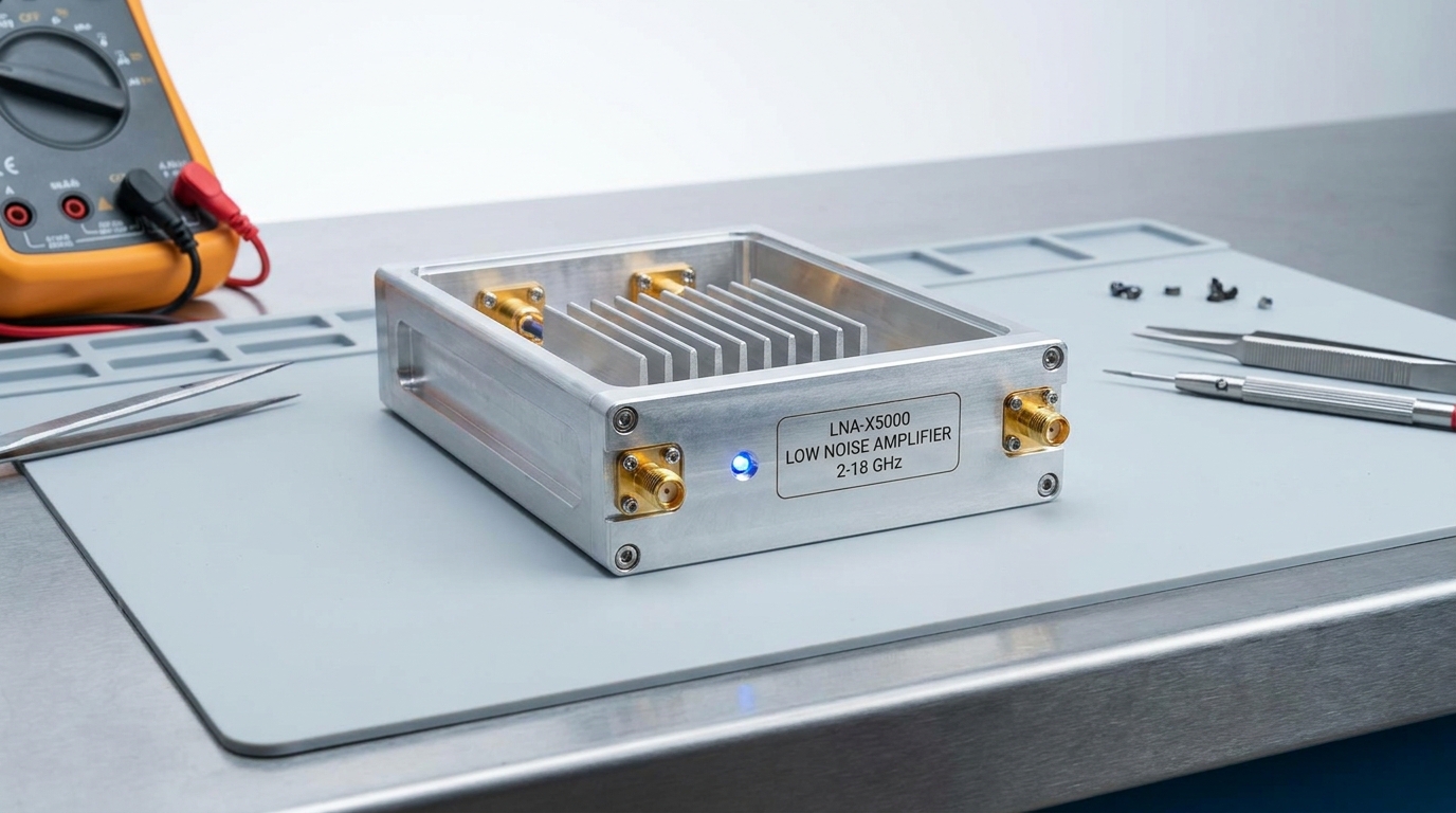
How does packaging influence thermal and RF performance?
Packaging influences the Low Noise Amplifier by providing a path for heat dissipation and creating a shield against external interference. In high-frequency applications, the physical layout of the package and its connectors can introduce parasitic capacitance and inductance. Choosing a robust, well-shielded package is essential for maintaining performance in harsh outdoor or industrial environments.
Does connector type affect RF performance?
Yes, the choice of connectors on a Low Noise Amplifier—such as SMA, N-type, or waveguide—dictates the frequency range and the amount of connection loss. At millimeter-wave frequencies, waveguide interfaces are often required to maintain the ultra-low Noise Figure.
Look at it this way:
- SMA is standard for most 18 GHz applications.
- Waveguide is superior for 40 GHz and above.
- Connector quality directly affects the VSWR.
How does thermal management extend life?
Even though a Low Noise Amplifier draws low power, any heat generated must be efficiently removed to prevent the Noise Figure from rising. Higher temperatures naturally increase thermal noise, making a cool-running LNA inherently “quieter.”
The best part?
- Heatsinks prevent “thermal runaway.”
- Shielded enclosures block ambient RFI.
- Rugged packaging supports deployment in SATCOM dishes.
Key Takeaway: The package is more than a box; it is a thermal and electromagnetic shield that preserves the amplifier’s sensitive internals.
| Package Type | Thermal Path | RF Shielding |
|---|---|---|
| Integrated Module | Internal | Excellent |
| SMT Chip | PCB Dependent | Moderate |
| Rugged Enclosure | External Fins | Maximum |
Conclusion
Selecting a peerless Low Noise Amplifier is the most significant decision you can make to improve the sensitivity and range of your RF system. By mastering the balance between Noise Figure, gain, and linearity, you can overcome the challenges of weak signals and noisy environments. Whether you are building a satellite ground station or a precision lab setup, the right LNA ensures your data remains clear and actionable.
At CorelixRF, we believe that performance should never be an estimate. Our brand stance is built on factory-direct validation, where every unit is tested individually to ensure it meets the rigorous demands of modern engineering. From wideband modules to high-frequency systems, we provide the hardware and technical documentation you need to succeed. If you are ready to elevate your receiver performance, contact us today to discuss your specific requirements with our engineering team.
Frequently Asked Questions
Can I use a Low Noise Amplifier for high-power transmission?
No, an LNA is designed specifically for receiving weak signals and will likely be destroyed if subjected to high-power transmit levels.
What’s the best way to protect an LNA from lightning?
The most effective method is to use a high-quality lightning arrestor and proper grounding between the antenna and the LNA input.
How do I know if my LNA is oscillating?
You will typically see a massive spike in current draw and a complete loss of signal, often visible as a broad “hump” of noise on a spectrum analyzer.
Can I cascade two LNAs for more gain?
Yes, you can, but the second LNA will amplify the noise of the first one; ensure the first LNA has the lowest possible Noise Figure.
What is the typical lifespan of a high-end LNA?
When operated within its thermal and power limits, a solid-state LNA can reliably exceed 100,000 hours of continuous operation.