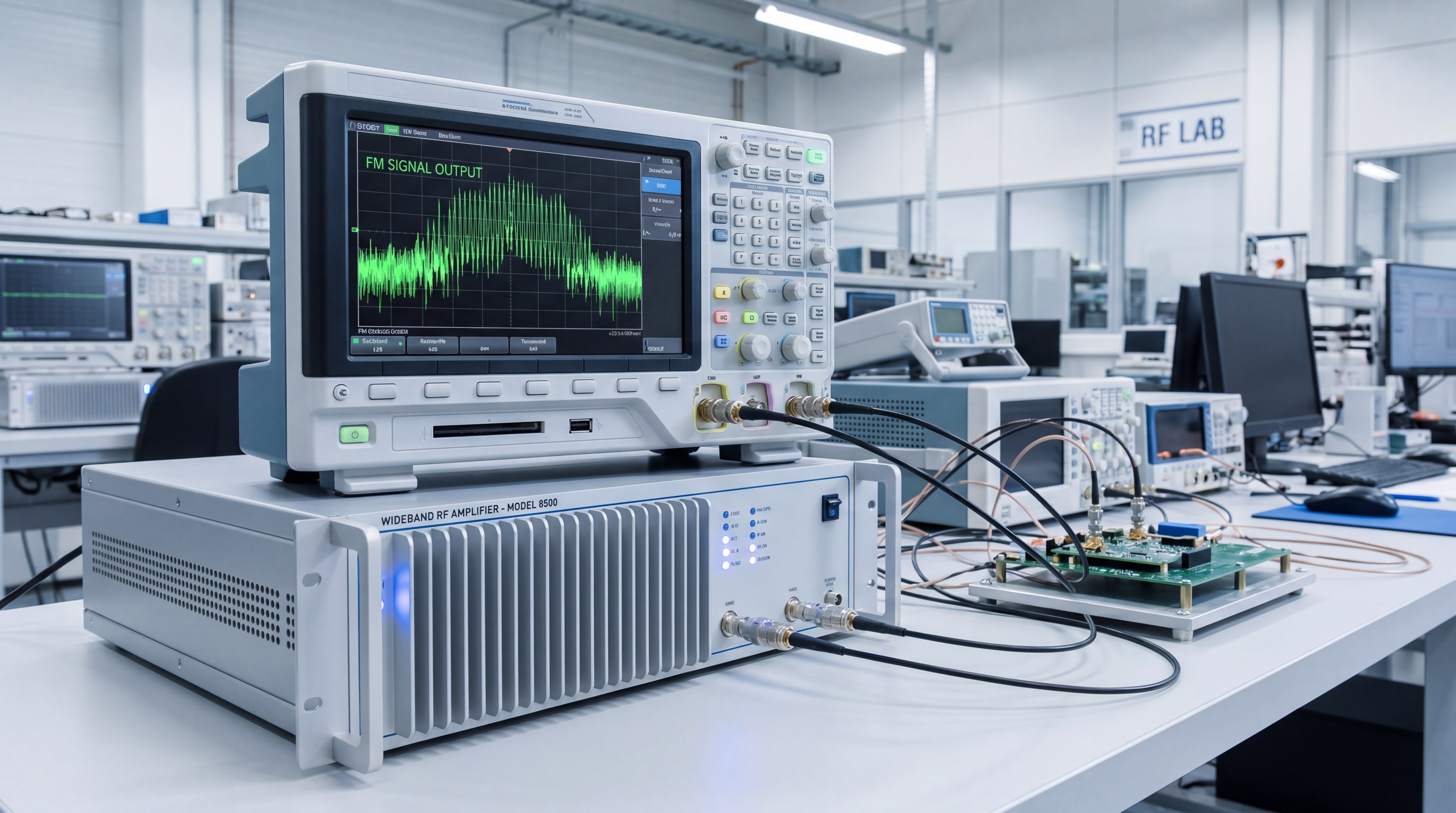
RF power amplifiers are vital for frequency-modulated (FM) signals because they provide the necessary wideband linearity and stable power density required to preserve frequency deviations without introducing parasitic amplitude noise. In high-speed communication and radar systems, these signals often suffer from severe distortion when passed through standard amplification stages that lack sufficient bandwidth. You might find that a weak signal is manageable, but a distorted FM signal renders an entire satellite link or drone radar system useless. Without precision power management, the “chirp” in your radar or the clarity in your 5G stream becomes unintelligible noise, leading to critical system failure. High-performance RF Power Amplifier technology designed specifically for wideband FM applications provides the thermal stability and phase purity required to maintain your signal integrity across complex environments.
1. What Makes FM Signal Amplification Unique?
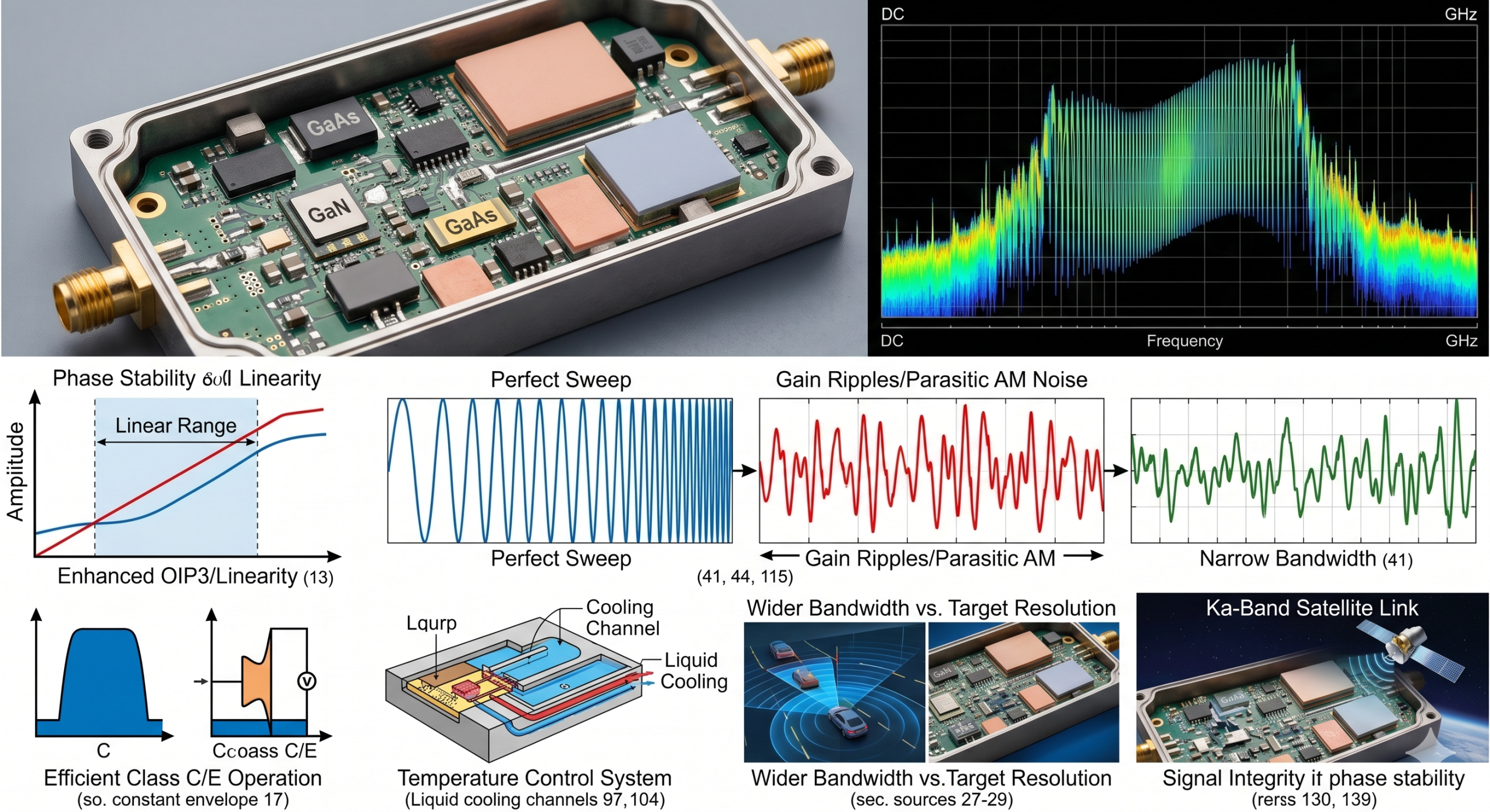
Amplifying FM signals is unique because it requires a constant envelope power output that remains stable even as the instantaneous frequency shifts rapidly across a wide bandwidth. Using a high-quality RF Power Amplifier ensures that these frequency deviations are not clipped or compressed by the hardware. You must prioritize phase stability over simple amplitude gain to avoid corrupting the encoded data.
Why is wideband support critical for FM?
The truth is: FM signals occupy varying frequency widths depending on the modulation index and the data rate being transmitted. If your hardware is restricted to a narrowband range, you will inevitably lose the sidebands that contain vital signal information.
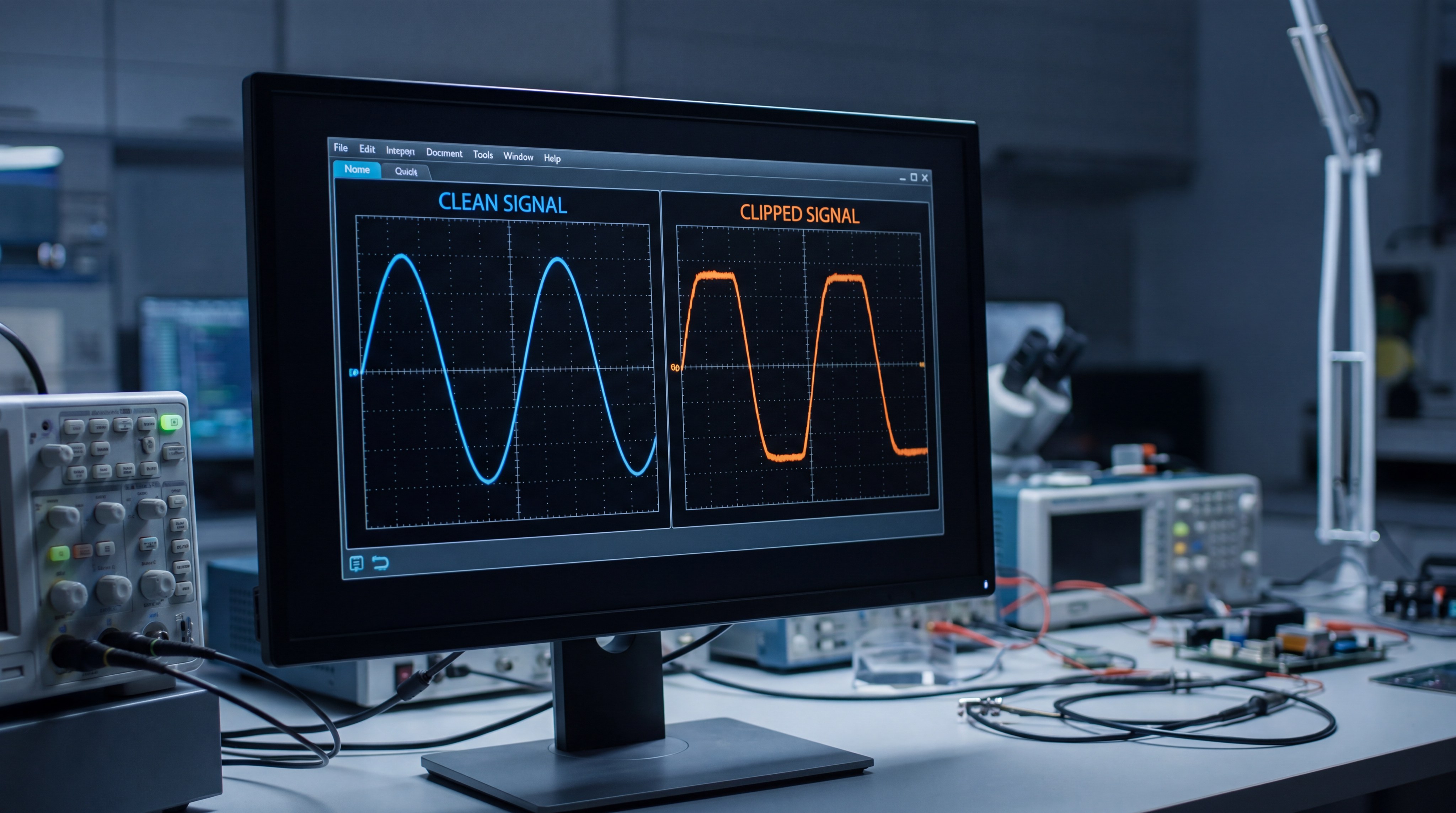
- Wideband support prevents signal clipping during peak frequency deviations.
- It ensures the preservation of the modulation index for high-fidelity data.
- Modern radar “chirps” require massive instantaneous bandwidth coverage.
How does modulation affect power efficiency?
Think about it: the continuous wave (CW) nature of FM allows you to utilize different amplifier bias classes that would be too non-linear for AM signals. Because the envelope is constant, you can push the system closer to saturation to maximize your power-added efficiency (PAE).
- Constant envelope signals allow for more efficient Class C or E operation.
- Efficiency depends on the system’s ability to maintain thermal equilibrium.
- Proper biasing reduces the risk of phase noise during high-speed transitions.
Key Takeaway: FM signals demand consistent gain and phase response across their entire frequency sweep to prevent data corruption and maintain link range.
| Feature | FM Amplification Requirement |
|---|---|
| Bandwidth | Must exceed maximum signal deviation |
| Power Density | Constant across the modulated spectrum |
| Primary Priority | Phase stability and gain linearity |
This comparison highlights why standard amplifiers often fail in specialized FM applications like wideband radar.
2. Is Your RF Power Amplifier Bandwidth Sufficient?
A sufficient bandwidth for an RF Power Amplifier must exceed the maximum frequency deviation of the signal to ensure that no spectral components are attenuated. You need to evaluate the full operating range of your system, from DC to high GHz frequencies, depending on the specific application. Insufficient bandwidth leads to a loss of resolution in radar and a drop in throughput for cellular networks.
How do wideband systems improve target resolution?
Here is the kicker: in FMCW radar systems, the resolution of your target detection is directly proportional to the bandwidth of the frequency sweep. By using a wider spectrum, you can distinguish between two objects that are positioned very close together.
- Wider sweeps provide finer distance measurements in automotive radar.
- High-resolution detection depends on the steepness of the frequency slope.
- It allows for better clutter rejection in complex electromagnetic environments.
Does your application need DC to GHz coverage?
The best part? Some general-purpose laboratory applications require amplification that starts from near DC and extends deep into the microwave range. This flexibility allows you to use a single piece of hardware for multiple modulation schemes and testing scenarios.
- DC-coupled amplifiers are ideal for specialized scientific measurements.
- High-frequency coverage is essential for 5G and satellite backhaul.
- Multi-octave performance reduces the need for expensive hardware switching.
Key Takeaway: Bandwidth is the most critical metric for determining if your hardware can handle modern high-resolution FM waveforms.
| Application | Bandwidth Necessity |
|---|---|
| Automotive Radar | Ultra-wide (Multiple GHz) |
| 5G Communication | Wide (Hundreds of MHz) |
| Satellite Comms | Focused High-Frequency segments |
A broader bandwidth directly translates to higher data capacity and superior radar sensitivity for your project.
3. Why Does Gain Flatness Matter for FM Systems?
Gain flatness is critical because fluctuations across the frequency band can introduce unintended amplitude modulation onto your constant-envelope FM signal. Utilizing an RF Power Amplifier with high gain flatness ensures that your receiver sees a uniform power level regardless of how far the frequency shifts. If your gain “ripples” too much, it can degrade the signal-to-noise ratio and complicate the demodulation process.
Can gain ripples distort your FM signal?
Look: gain fluctuations cause what engineers call AM-to-PM conversion, which directly inserts phase noise into your transmission. This distortion is particularly damaging in satellite links where the signal must travel vast distances through various atmospheric conditions.
- Minimal gain variation preserves the signal-to-noise ratio.
- Flatness prevents the receiver from misinterpreting power drops as noise.
- Consistent power delivery across the band protects sensitive components.
How do we measure acceptable gain variation?
In simple terms: most high-end B2B applications require a gain variation of less than ±1.5 dB across the entire operational bandwidth. You should always look for hardware that provides a smooth response curve without sharp dips or peaks at the band edges.
- Industry standards typically target ±1.0 to ±2.0 dB of flatness.
- Designers must account for gain drop-off as the device approaches its limits.
- Precise internal matching circuits are required to maintain this stability.
Key Takeaway: Maintaining a flat gain response is the primary way to prevent the unintended introduction of noise during rapid frequency transitions.
| Metric | High-Quality Standard |
|---|---|
| Gain Flatness | ±1.0 dB to ±1.5 dB |
| Signal Integrity | High (minimal parasitic AM) |
Selecting an amplifier with superior flatness ensures your system remains reliable across all operating frequencies.
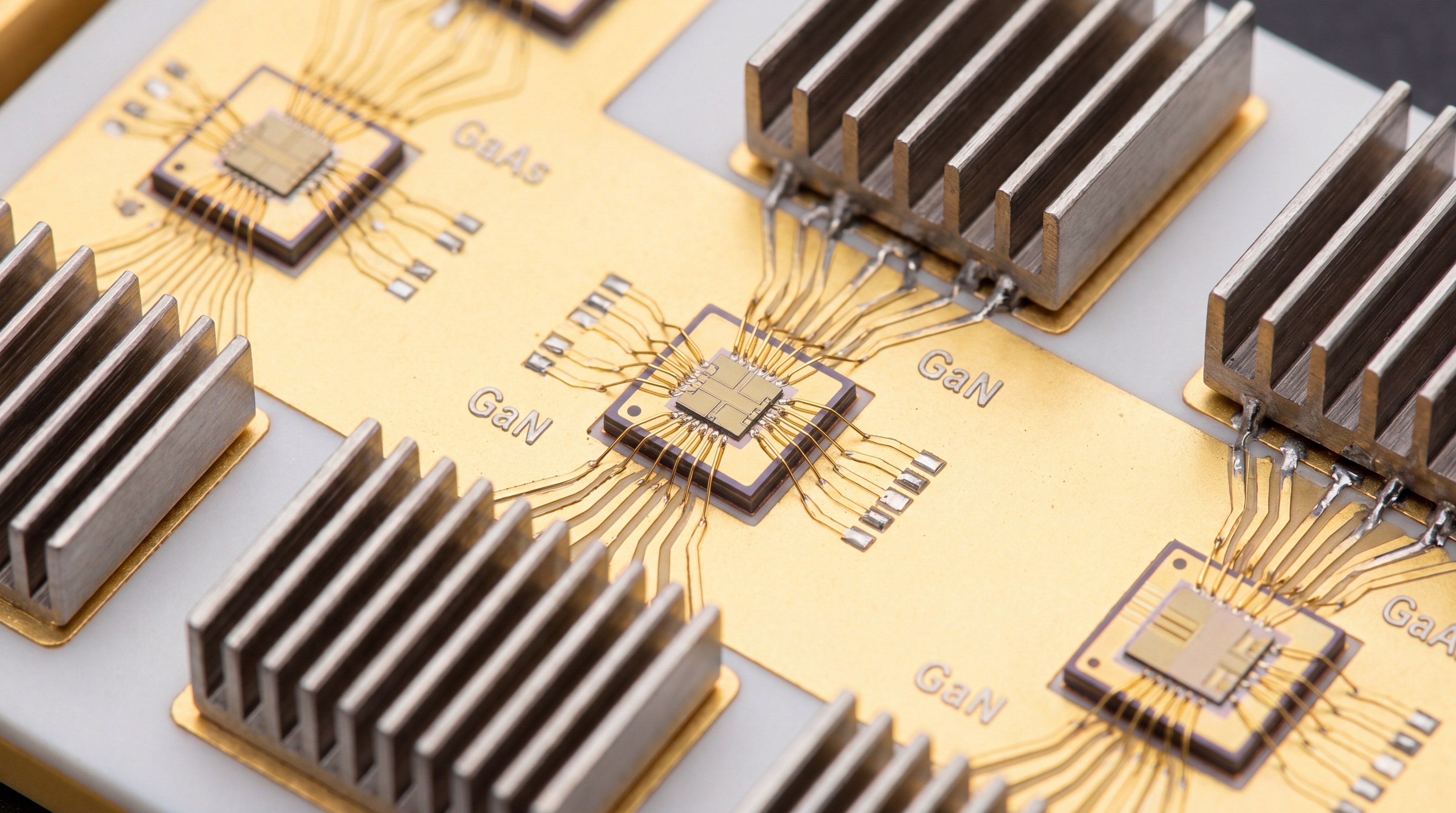
4. How Do GaN and GaAs Impact RF Power Amplifier Design?
The choice between GaN and GaAs semiconductors for your RF Power Amplifier determines the frequency range, power density, and thermal efficiency you can achieve. GaAs is often the standard for lower GHz frequencies where cost-efficiency and high linearity are the main priorities for your design. However, as your requirements move into the higher microwave and millimeter-wave bands, the material properties of the semiconductor become the limiting factor.
When is GaAs the right choice for FM?
The reality is: GaAs devices provide excellent performance for sensitive communication signals that do not require multi-kilowatt power levels. If you are working on short-range consumer devices or standard LTE bands, GaAs offers a mature and reliable technology path.
- It provides high linearity for complex modulation schemes.
- Lower manufacturing costs make it ideal for high-volume production.
- Superior noise performance at lower power levels benefits signal reception.
Why is GaN dominating the high-frequency market?
But wait, there’s more: Gallium Nitride (GaN) can handle significantly higher power densities and operating voltages than traditional materials. This makes it the undisputed leader for defense applications and high-frequency satellite communications where every watt of power is critical.
- GaN supports much higher junction temperatures without failure.
- It enables the creation of smaller, more powerful amplifier modules.
- Superior performance at 18 GHz and above is standard for GaN.
Key Takeaway: Your choice of semiconductor material should be driven by the specific balance of frequency, power, and thermal constraints in your system.
| Material | Best Frequency Range | Power Capability |
|---|---|---|
| GaAs | < 6 GHz | Moderate |
| GaN | 6 GHz to 100+ GHz | High |
GaN is the go-to solution for high-power, high-frequency requirements, while GaAs remains a cost-effective choice for lower-power bands.
5. Are Radar and Cellular Requirements the Same?
Radar and cellular systems have vastly different operational goals, yet they both rely on an RF Power Amplifier to maintain signal purity across wide bandwidths. While radar systems use massive frequency sweeps to detect speed and distance, cellular networks use complex modulation to maximize data throughput. You will find that both applications demand high linearity, but the way they utilize the spectrum varies significantly.
How does chirped radar differ from 5G?
It comes down to this: radar “chirps” are essentially long-duration frequency ramps that require the amplifier to stay linear over a very wide instantaneous range. In contrast, 5G signals occupy fixed channels but use complex modulation like QAM which requires high spectral efficiency.
- Radar focuses on distance resolution and target velocity detection.
- 5G focuses on capacity, latency, and multi-user connectivity.
- Both systems benefit from amplifiers with a high 1dB compression point.
Do both require high linearity?
Interestingly enough: yes, though for different reasons. For radar, linearity ensures that the frequency ramp is perfectly straight, while for 5G, it prevents signal leakage into adjacent channels.
- High linearity prevents “spectral regrowth” in communication bands.
- It ensures that radar sweeps do not produce false target artifacts.
- Thermal stability is required for both to avoid signal drift.
Key Takeaway: While the waveforms and end goals are different, both industries require wideband performance and robust thermal management.
| System Type | Waveform Characteristic | Amplification Goal |
|---|---|---|
| FMCW Radar | Continuous Sweep | Precise Frequency Response |
| 5G Cellular | Complex Modulation | High Throughput / Low Noise |
Understanding these differences helps you select hardware that is optimized for your specific operational environment.
6. Can an RF Power Amplifier Handle Heat Without Drift?
Managing thermal energy in an RF Power Amplifier is essential because heat directly changes the electrical properties of the semiconductor junctions. If your system gets too hot, you will experience gain drift, where the output power fluctuates by several decibels. This is particularly dangerous for FM signals where consistent power is needed to maintain the link budget in long-range transmissions.
Why does temperature cause output deviation?
Let’s face it: as the internal components heat up, their ability to move electrons efficiently decreases, leading to a drop in gain. You might notice that your signal becomes weaker or more distorted after the system has been running at full power for several minutes.
- Heat alters the bias points of the internal transistors.
- High-power operation can lead to permanent component degradation if unmanaged.
- Temperature shifts can cause phase errors in sensitive modulation schemes.
How do we stabilize high-power modules?
The solution? Integrated thermal compensation circuits and advanced cooling methods like liquid heat-sinking are standard for multi-kilowatt systems. These features ensure that the output remains stable regardless of the environmental temperature or the duration of operation.
- Liquid cooling is necessary for high-power systems above 1 kW.
- Integrated sensors can automatically adjust gain to compensate for heat.
- High-quality enclosures act as effective heat sinks for smaller modules.
Key Takeaway: Effective thermal management is just as important as electrical design for maintaining a consistent signal in field operations.
| Cooling Method | Power Range | Typical Application |
|---|---|---|
| Air Cooled | 20W – 500W | Laboratory / UAV Comms |
| Liquid Cooled | 1kW+ | High-Power Defense Radar |
Proper cooling ensures that your system maintains peak performance during long-term deployments.
7. What Role Does the 3rd Order Intercept Point Play?
The 3rd Order Intercept Point (OIP3) is a theoretical metric that defines the usable input range of your RF Power Amplifier before distortion becomes unmanageable. It measures the amplifier’s ability to handle intermodulation, which is critical when multiple frequencies are being processed simultaneously. A higher OIP3 value indicates that you can run higher input power levels while keeping your output signal clean and free of interference.
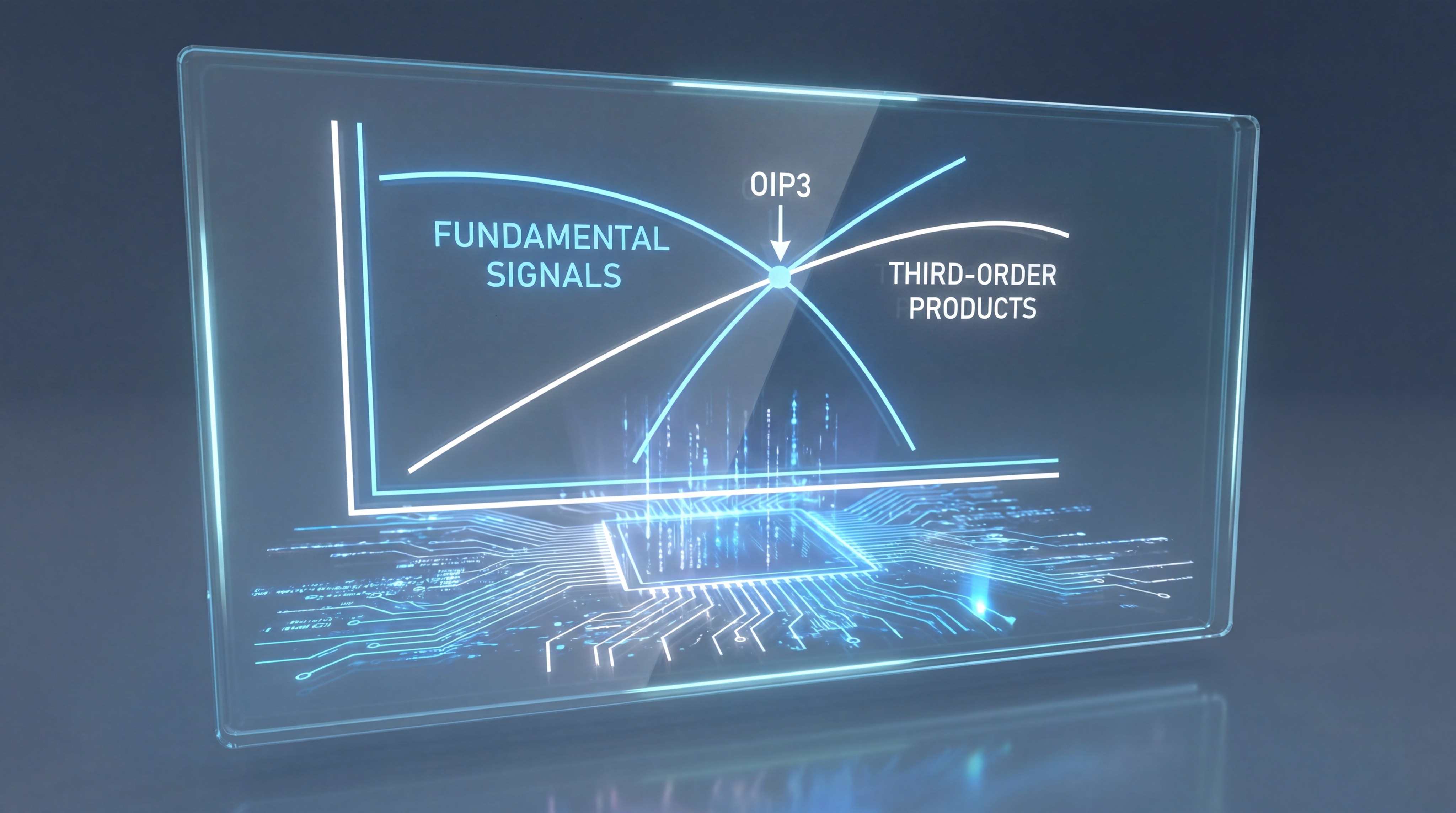
Does OIP3 define your usable input range?
Here’s the deal: OIP3 tells you exactly where the distortion products will eventually equal the strength of your desired signal. By keeping your operating power well below this point, you ensure that your FM signal remains pure and free of parasitic noise.
- A higher OIP3 allows for a wider dynamic range in your receiver.
- It prevents signal masking where distortion hides the actual data.
- High OIP3 is essential for multi-carrier communication environments.
Why avoid third-order products in FM?
Simply put: intermodulation products are problematic because they often land directly on or near your desired frequency band. Unlike other types of noise, these products cannot be easily filtered out once they are created within the amplifier.
- Third-order products can interfere with neighboring communication channels.
- They increase the total noise floor of your electronic system.
- Distortion products degrade the clarity of radar target detection.
Key Takeaway: A high OIP3 ensures that your amplifier remains linear even when handling complex, multi-tone signals in crowded spectrums.
| Parameter | Impact on FM Signal |
|---|---|
| High OIP3 | Cleaner spectrum and less interference |
| Low OIP3 | Increased noise floor and signal masking |
Choosing hardware with a high OIP3 is the best way to future-proof your system against interference.
8. How Do You Match an RF Power Amplifier to Satcom?
Matching an RF Power Amplifier to satellite communication (Satcom) requires a deep understanding of the specific frequency bands, such as Ku or Ka, and the power required to reach orbit. You must balance the need for raw output power with the stringent requirements for phase noise and linearity. If your amplifier is not perfectly matched to the antenna and the waveform, you will experience significant signal loss before it even leaves the ground station.
Which bands are standard for satellite FM?
You might wonder: why are some bands more popular than others for frequency modulation in space? The S, X, Ku, and Ka bands are the workhorses of the industry because they offer the best balance between atmospheric penetration and data capacity.
- S-Band is commonly used for weather monitoring and basic telemetry.
- Ka-Band is the standard for modern high-speed satellite internet data.
- Each band requires specialized hardware to handle its unique frequencies.
Is saturation power the most important stat?
Not necessarily: while saturation power (Psat) tells you the maximum possible output, FM systems often need to run at the 1dB compression point (P1dB) to maintain linearity. Operating too close to saturation can cause phase distortion that ruins the data link over long distances.
- Running at P1dB provides a safety margin against signal distortion.
- Phase stability is often more critical than raw wattage in Satcom.
- Saturation should only be used in systems where phase is not the primary carrier.
Key Takeaway: Satcom amplifiers must prioritize phase stability and linearity to ensure reliable data transmission across thousands of miles.
| Satellite Band | Frequency Range | Primary Use Case |
|---|---|---|
| S-Band | 2.0 – 4.0 GHz | Telemetry / Weather |
| Ka-Band | 26.5 – 40.0 GHz | High-Speed Broadband |
Selecting the right band and power level is the first step in building a successful satellite link.
9. Is Linear Range the Ultimate Performance Metric?
The linear range of an RF Power Amplifier is perhaps the most important metric for modern 5G and radar systems because it determines how much “clean” headroom you have for signal spikes. You need a vast linear range to handle signals with high peak-to-average power ratios (PAPR) without clipping the waveforms. If your linear window is too narrow, you will experience immediate data errors as the signal peaks are compressed by the hardware.
Why is a vast linear range necessary for 5G?
To be honest: 5G signals are incredibly complex and feature rapid spikes in power that can easily overwhelm a standard amplifier. Without a wide linear range, these peaks are “clipped,” causing the receiver to lose bits of data and reducing the overall speed of the network.
- A wide linear range supports higher-order modulation like 256-QAM.
- It reduces the need for aggressive digital pre-distortion (DPD).
- Consistent linearity ensures that the signal stays within its assigned band.
Can you sacrifice linearity for cost?
That’s a risky move: low-cost amplifiers often have very narrow linear windows that may work for simple FM radio but fail completely for modern data-heavy systems. You will likely spend more money in the long run trying to fix the resulting signal errors and hardware failures.
- Narrow linear windows lead to frequent signal drops and packet loss.
- Inexpensive hardware often lacks the thermal protection needed for stability.
- High-quality linear amplifiers provide a much longer operational lifespan.
Key Takeaway: Linear range is the ultimate metric for ensuring that your signal remains “clean” even during maximum power peaks.
| Metric | High Linear Range | Low Linear Range |
|---|---|---|
| Signal Quality | Excellent / High Fidelity | Poor / Frequently Clipped |
| Cost-Effectiveness | High (Long-term stability) | Low (Constant errors) |
Investing in a high linear range is essential for any project that requires high data throughput.
10. Why Should You Choose Factory-Direct RF Power Amplifiers?
Choosing a factory-direct RF Power Amplifier manufacturer gives you a significant advantage in terms of technical support, customization, and lead times. When you bypass distributors, you gain direct access to the engineers who actually designed the hardware, allowing for faster troubleshooting and more precise project matching. You also receive verified unit-level test data, which is rarely provided by third-party resellers.
Does buying direct reduce your lead time?
The short answer? Yes, because you are not waiting for a middleman to process your order or wait for stock to arrive from a remote warehouse. Factory-direct sourcing puts you at the front of the manufacturing queue, which is critical for time-sensitive defense or infrastructure projects.
- Direct communication speeds up the procurement and shipping process.
- You get real-time updates on the production status of your hardware.
- It eliminates the markup and delays associated with distributors.
Are custom modifications easier with the manufacturer?
Absolutely: since the factory controls the entire design and assembly process, you can request specific modifications to the connectors, gain levels, or enclosure types. This level of flexibility is impossible to find when buying standardized catalog items from a distributor.
- Custom mechanical integration is available for OEM projects.
- Engineers can tune standard platforms to your specific frequency range.
- You receive individual test data for every unit you purchase.
Key Takeaway: Sourcing directly from the manufacturer ensures the highest level of quality control and the fastest path to system integration.
| Sourcing Method | Engineering Access | Test Data Reliability |
|---|---|---|
| Factory-Direct | Direct Review with Engineers | Verified Individual Unit Data |
| Distributor | Limited or None | Generic Sample Datasheets |
Direct sourcing is the smartest choice for engineering teams who need reliable, high-performance hardware.
FAQ
- Can I use a narrowband amplifier for chirped radar?
No, you cannot use a narrowband amplifier because the rapid frequency sweeps of a radar chirp will be clipped, leading to a loss of target resolution. - What’s the best semiconductor for high-frequency FM?
GaN is generally the best choice for frequencies above 6 GHz because it offers superior power density and thermal stability. - How do I know if my RF Power Amplifier is overheating?
You will typically see a sudden drop in gain or a significant increase in signal distortion as the internal junctions reach their thermal limits. - What is the best way to ensure gain flatness?
The best way is to select an amplifier with integrated leveling circuits or to use high-quality internal matching that is factory-verified. - Can I customize an amplifier for specific 5G bands?
Yes, factory-direct manufacturers like CorelixRF can tune their standard platforms to optimize performance for your specific 5G frequency range.
Conclusion
Successfully deploying frequency-modulated signals requires more than just a standard amplifier; it requires a precision instrument designed for wideband stability and high linearity. At CorelixRF, our vision is to bridge the gap between complex RF theory and practical, factory-backed hardware that technical buyers can trust. We don’t just supply components; we provide a verified engineering path from initial requirement review to validated system delivery. Whether you are building a high-resolution radar system or a high-capacity satellite link, our team is ready to provide the expertise and hardware needed to ensure your success. Contact us today to discuss your project and receive a professional engineering review within 48 hours.