
Desert operations often present mysterious hardware failures. A sudden output drop leaves remote operators completely blind. We address mechanical mounting faults causing thermal warping today. You will learn diagnostic methods utilizing physical evidence. Here’s the deal, correct fastening prevents catastrophic field breakdowns permanently.
1. Why Do Unmanned Desert Stations Experience Sudden RF Power Drops?
Operators face severe challenges operating communication hardware within arid environments. Ambient heat pushes internal components near operational limits during midday sunlight. An unexpected forward-power alarm suddenly triggers within your remote management dashboard. Network analyzer sweeps show no antenna mismatch whatsoever. Reflected energy remains exceptionally low. Forward output simply vanishes into thin air. You might be wondering, what causes this phantom failure? A typical technician assumes semiconductor death immediately. They swap out faulty modules blindly without thinking. Such actions ignore underlying mechanical realities entirely. An investigation requires physical site visits utilizing proper tools. Bringing thermal imagers helps isolate heat anomalies effectively. We must examine physical hardware mounting carefully. That baseplate surface holds critical clues revealing past mistakes. Neglecting mechanical installation protocols guarantees repeated failures constantly. Let us examine physical evidence left behind by careless assembly procedures. Desert sandstorms exacerbate these thermal problems daily. Blocked external radiators reduce overall system cooling capacity significantly. When external cooling drops, internal thermal pathways become incredibly critical. A poorly mounted device fails instantly under such extreme environmental stress.
High Ambient Temperatures
Scorching desert air removes all thermal safety margins.
Dust and Sand Accumulation
Abrasive particles clog external heat sinks rapidly.
Remote Monitoring Limitations
Software dashboards rarely show localized physical warping.
| Parameter | Typical Desert Condition | System Impact |
| Ambient Air | $+50^\circ C$ | Reduces cooling margin |
| Direct Solar | Extreme | Raises chassis baseline |
| Sand Ingress | High | Blocks heat sinks |
| Thermal Cycle | Wide variation | Causes mechanical stress |
2. How Does Improper Screw Torque Affect Thermal Conduction?
Mechanics understand torque distribution intimately through daily practice. RF engineers sometimes overlook basic mechanical assembly practices completely. Fastening a rectangular baseplate requires alternating diagonal tightening sequences. Securing one side completely before starting another creates microscopic warping. Aluminum chassis plates flex under uneven stress dynamically. This creates minute air gaps between your amplifier and its heatsink. Air constitutes an excellent thermal insulator naturally. Heat generated by power transistors cannot escape downward efficiently. This is where it gets interesting, because localized hot spots develop directly under high-dissipation components. Thermal paste cannot bridge massive structural gaps caused by bent metal. A warped $200\times158\times25~mm$ package traps energy internally. Device junctions overheat rapidly beyond safe limits. Transistor efficiency plummets alongside overall gain levels. Consequently, early degradation occurs without triggering immediate VSWR alarms. Our factory engineers witness this specific failure mode frequently. Clients return units claiming spontaneous power loss occurred. Laboratory teardowns reveal perfectly functional circuits ruined by structural bending. Proper torque wrench usage prevents these expensive field disasters completely.
The Physics of Bending
Uneven torque forces metal sheets out of flatness.
Thermal Paste Limitations
Grease fills microscopic voids, not macroscopic structural bends.
Heat Trapping Mechanisms
Trapped thermal energy reflects back into sensitive silicon junctions.
| Fastening Method | Air Gap Formation | Thermal Resistance | Degradation Speed |
| Circular Sequential | Moderate edge lift | Medium | Weeks |
| Single Side First | Severe center bow | Very High | Hours |
| Diagonal Alternating | None | Minimum | Normal Lifespan |
3. What Physical Evidence Reveals Poor Baseplate Contact?
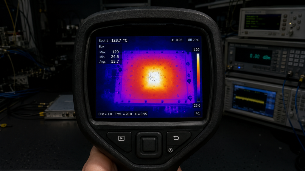
Field technicians arrive at remote desert sites seeking answers. A FLIR camera reveals immediate thermal signatures upon opening equipment enclosures. Normally, an RF module exhibits uniform heat distribution across its top surface. A poorly mounted unit displays intense glowing red centers surrounded by cold edges. What’s the real story? Unbolting that suspected module provides undeniable proof immediately. Examine residual thermal grease patterns on both mating surfaces carefully. A properly installed unit shows thin, even paste distribution everywhere. Warped installations leave thick, untouched paste areas near center regions. Metal-to-metal contact only occurs near overtightened corners. These dry spots indicate zero thermal transfer occurred during operation. Gallium Nitride devices operating at 150 W demand flawless conductive pathways. Without proper cooling, semiconductor materials degrade rapidly under high current loads. We train our field support teams identifying these grease patterns immediately. A quick visual inspection saves hours diagnosing nonexistent electrical faults. Always document grease distribution photographically before cleaning suspected failed hardware.
FLIR Camera Diagnostics
Infrared imaging spots uneven temperature gradients instantly.
Thermal Grease Analysis
Leftover paste patterns map physical contact zones perfectly.
Post-Mortem Verification
Measuring baseplate flatness confirms mechanical distortion hypotheses.
| Diagnostic Tool | Field Observation | Probable Cause |
| Thermal Imager | Center hotspot, cool edges | Center air gap |
| Power Meter | Gradual output decay | Thermal gain roll-off |
| Visual Inspection | Uneven thermal compound | Warped baseplate |
4. How Do Electrical Parameters React to Thermal Warping?
Heat destroys radio frequency performance methodically over time. As internal temperatures rise beyond normal limits, carrier mobility within semiconductor channels decreases. This physical phenomenon causes immediate current draw increases. Our standard specifications indicate current consumption remaining $\le22$ A under optimal conditions. An overheating transistor demands more current attempting constant output delivery. Supply voltage remains steady at 28 VDC, pushing total power dissipation higher. Ready for the good part? This cascading failure accelerates rapid self-destruction. Rated output power of 150 W drops sharply as thermal protection engages or junctions melt. You might measure a 52 dB typical gain initially. Thirty minutes later, that figure collapses by several decibels. Monitoring telemetry data closely reveals this slow decay pattern. Smart monitoring software detects creeping current consumption easily. Setting early warning thresholds saves expensive hardware from total destruction. Engineers must correlate rising current draws against ambient temperature readings continuously.
Current Draw Spikes
Lost efficiency forces power supplies harder.
Gain Compression Anomalies
Hot transistors lose amplification linearity quickly.
Total Output Collapse
Eventually, protective circuits trigger system shutdowns.
| Parameter | Normal Operation | Overheating State |
| Current Consumption | $\le22$ A | Spiking above limits |
| Output Power | 150 W | Rapidly dropping |
| Typical Gain | 52 dB | Collapsing steadily |
| Baseplate Temp | Cool | Extremely hot |
5. Why Does the CRF-PA-300M1700M-150W Survive Extreme Conditions?
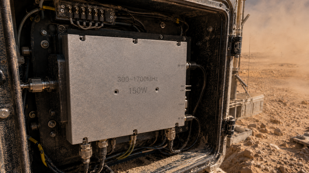
CorelixRF designs rugged hardware specifically targeting harsh operational environments. We engineer our modules acknowledging field technicians face brutal desert challenges daily. The CRF-PA-300M1700M-150W operates across a 300-1,700 MHz frequency range. This wideband capability requires superior structural integrity alongside electrical excellence. But here’s the kicker, our mechanical chassis utilizes stress-relieved aerospace aluminum. Weighing $\le1.4$ kg, this block resists deformation during improper mounting attempts. Thick baseplate construction minimizes bowing risks even if a technician rushes installation. Furthermore, its specified operating temperature spans from -40 to $+85^\circ C$. This provides massive thermal headroom above typical desert ambient levels. Solid mechanical foundations guarantee long-term electrical reliability perfectly. We machine our baseplates achieving exceptional flatness tolerances consistently. Flawless surface finishing maximizes thermal paste effectiveness automatically. Investing into superior metalwork prevents mysterious field failures saving massive maintenance costs eventually.
Aerospace Aluminum Construction
Rigid metal blocks resist bending forces.
Extreme Temperature Ratings
Built specifically handling hostile climates confidently.
Precision Machined Surfaces
Flatness guarantees flawless mating against system heatsinks.
| Feature | Specification | User Benefit |
| Frequency Range | 300-1,700 MHz | Wideband utility |
| Rated Output Power | 150 W | High impact jamming |
| Operating Temp | -40 to $+85^\circ C$ | Desert survival |
| Weight | $\le1.4$ kg | Lightweight ruggedness |
6. What Are The Specific Mechanical Dimensions Assisting Integration?
System integrators demand precise mechanical outlines planning remote equipment enclosures. Fitting high-power amplifiers into compact pods requires strict dimensional control. Our detailed datasheet provides comprehensive mechanical drawings supporting accurate CAD modeling. The entire package size measures $200\times158\times25~mm$. This low-profile geometry allows integration within tight spaces while leaving room for auxiliary cooling fans. Let’s look closer, physical interfaces feature robust industrial connectors. An SMA-Female handles incoming signals. Output power routes through a heavy-duty N-Female connector. Standard DB9 interfaces manage control and monitoring telemetry. These secure connections withstand high-frequency vibrations associated with transport across rough desert terrain. Placing connectors strategically along one edge simplifies cable routing significantly. Neat wiring layouts reduce physical strain acting upon sensitive RF joints. A well-designed pod layout improves overall system survivability dramatically.
Compact Form Factor
Low height fits inside restricted aerodynamic pods.
Robust Connectors
Heavy duty threads prevent accidental uncoupling.
Simplified Cable Management
Unidirectional interfaces streamline internal pod wiring.
| Dimension | Measurement | Function |
| Package Size | $200\times158\times25~mm$ | Spatial planning |
| RF Input | SMA-Female | Signal entry |
| RF Output | N-Female | Power exit |
| Control Port | DB9 | Telemetry access |
7. How Do We Guarantee Performance Before Deployment?
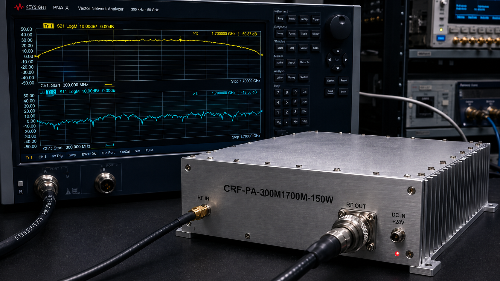
Verification remains mandatory before deploying assets into isolated regions. CorelixRF maintains strict quality frameworks guaranteeing every unit performs perfectly upon arrival. Our engineering team conducts rigorous laboratory evaluations utilizing calibrated network analyzers. We document actual swept measurements showing S21 gain and S11 input match. A typical performance curve demonstrates exceptional stability across wide frequency bands. This is the core truth, visual proof eliminates guesswork entirely. Gain flatness remains strictly $\le1.8$ dB. Input VSWR stays tightly controlled under $\le1.8$:1. Such precise laboratory verification prevents deploying defective equipment into expensive field operations. We provide these comprehensive test records upon client request. Examining these charts confirms our amplifiers meet advertised specifications perfectly. Our strict testing protocols identify hidden manufacturing defects long before shipping. Clients receive dependable hardware ready for immediate desert deployment.
Network Analyzer Sweeps
Visual graphs prove operational stability conclusively.
Flatness Verification
Consistent gain prevents unpredictable system behavior.
VSWR Quality Control
Matching protects internal circuits against reflected energy.
| Metric | Specification | Verification Method |
| Gain Flatness | $\le1.8$ dB | Swept S21 |
| Input VSWR | $\le1.8$:1 | Swept S11 |
| Output VSWR | $\le2.0$:1 | Swept S22 |
| Spurious | $\le-60$ dBc | Spectrum Analyzer |
8. What Makes Air Cooling Viable In Arid Climates?
Liquid cooling systems introduce unacceptable maintenance liabilities at remote sites. Leaks or pump failures doom unmanned desert stations immediately. Therefore, our design relies purely upon forced air cooling. Implementing reliable air dissipation requires highly optimized heatsink fin geometries matching our amplifier baseplate. A flat $200\times158\times25~mm$ surface transfers thermal loads into external radiators efficiently. Think about this, reducing mechanical complexity increases overall system survival rates. Operating at 28 VDC , our amplifier drives 150 W continuous wave energy. High electrical efficiency reduces total waste heat generation significantly. Fans merely push ambient desert air across external fins without contacting sensitive internal electronics directly. Keeping blowing sand outside sealed RF enclosures prevents catastrophic short circuits. This isolated cooling methodology extends equipment lifespans across hostile environments tremendously.
Passive Thermal Transfer
Heavy baseplates soak up sudden heat transients smoothly.
Fan Assisted Dissipation
External forced air removes steady state loads reliably.
Sealed Enclosure Architecture
Sensitive electronics remain protected against blowing sand.
| Cooling Aspect | Mechanism | Reliability Benefit |
| Cooling Method | Air Cooling | Zero liquid leaks |
| Voltage | 28 VDC | Standard industrial power |
| Output Type | CW/Saturated | Consistent heat profile |
| Harmonics | $\le-10$ dBc | Less wasted out-of-band energy |
9. How Does CorelixRF Support Custom Integration Projects?
Every radar or communication project presents unique environmental constraints demanding tailored solutions. Standard off-the-shelf items rarely fit perfectly within specialized military or industrial architectures. We offer deep customization addressing specific application requirements directly. Our engineering team reviews feasibility regarding custom frequency bands within 48 hours. Here’s the bottom line, we adapt our technology fitting your exact mechanical envelope. Options include alternative connectors or specialized control interfaces. Modifying integration details guarantees seamless compatibility alongside existing legacy hardware. By partnering with genuine manufacturing facilities, integrators bypass generic distribution limitations entirely. Direct communication lines between factory engineers and field technicians accelerate problem resolution. We understand your unique system architecture quickly. Rapid prototyping capabilities allow testing modified designs under actual field conditions fast.
Rapid Feasibility Studies
Engineering teams evaluate new requirements swiftly.
Interface Customization
Tailoring control pins matches proprietary client systems.
Factory Direct Collaboration
Cutting out middlemen accelerates technical problem solving.
| Customization Type | Availability | Turnaround Target |
| Feasibility Review | Within 48 hours | Extremely Fast |
| Custom Frequency Bands | Available | Project Dependent |
| Connector Changes | Available | Standard Lead Time |
| Integration Details | Fully Supported | Collaborative |
10. Why Does Strict Compliance Guarantee Long-Term Reliability?
Industrial hardware must survive decades operating autonomously under unforgiving skies. Meeting basic power output numbers represents merely one step toward true engineering excellence. We adhere rigorously strictly toward established global quality frameworks continuously. Every CRF-PA-300M1700M-150W model complies fully alongside CE and FCC regulations. Furthermore, our manufacturing processes follow ISO 9001 standards meticulously. Now pay attention, military-grade reliability requires specialized documentation sets. We provide GJB 9001C compliance data supporting advanced defense procurement programs. Mean Time Between Failure statistics remain available upon request. Such transparent reliability validation gives system architects profound confidence approving our designs. Thorough environmental validation data removes operational risks during project planning phases. CorelixRF delivers uncompromising quality backing every shipped unit unconditionally.
Regulatory Approvals
Meeting CE/FCC standards proves clean spectrum emissions.
Manufacturing Consistency
ISO 9001 certification guarantees repeatable unit construction.
Defense Grade Validation
GJB 9001C compliance qualifies hardware for advanced applications.
| Quality Standard | Certification Status | Implication |
| RoHS | Compliant | Environmentally safe |
| CE/FCC | Compliant | Regulatory passing |
| ISO 9001 | Certified | Quality management |
| GJB 9001C | Compliant | Defense readiness |
Conclusion
Improper baseplate mounting destroys high-power amplifiers rapidly through severe thermal isolation. Deploying robust hardware like our CRF-PA-300M1700M-150W alongside correct diagonal tightening procedures guarantees desert station survival. Contact CorelixRF engineers acquiring detailed MTBF statistics resolving your thermal management challenges permanently.
Frequently Asked Questions
Q1: What is the primary cause of early RF power degradation in desert stations?
Uneven baseplate tightening creates microscopic air gaps beneath power transistors. This prevents efficient heat transfer into external radiators. Semiconductor junction temperatures spike uncontrollably causing rapid gain collapse.
Q2: How does the CRF-PA-300M1700M-150W handle extreme ambient temperatures? This model utilizes a robust aluminum chassis rated for operating temperatures reaching $+85^\circ C$. Its thick baseplate resists mechanical warping guaranteeing maximum thermal transfer into your heat sink.
Q3: Why do technicians mistakenly blame semiconductor failure instead of mounting errors?
Thermal warping degrades output power silently without triggering immediate antenna VSWR alarms. Field operators observe vanishing forward power assuming internal component death while ignoring physical assembly flaws entirely.
Q4: What specific frequency range does this wideband amplifier cover? Our recommended hardware operates continuously across a wide 300-1,700 MHz spectrum. This broad coverage supports diverse testing and integration applications efficiently.
Q5: How can I verify baseplate contact quality during field maintenance?
Remove your amplifier module inspecting residual thermal grease patterns beneath it. Proper installations leave thin even coats everywhere. Warped units show thick untouched paste areas indicating zero contact occurred.
Convert thermal risk into measurable RFQ requirements
Thermal reliability should be specified with output power, duty cycle, ambient range, airflow or baseplate path, soak time, allowed gain drift and alarm behavior. These details help CorelixRF match the request to a standard or modified amplifier platform.
Recommended next step: send the operating band, output power target, duty cycle, load condition, control interface, protection or thermal limits and required FAT documents. CorelixRF can review this How to Execute Proper RF Amplifier Baseplate Mounting for Desert Pods? requirement against standard RF amplifier platforms, RF front-end options and controlled customization paths.