
1. What Are The Early Warning Signs Of Signal Anomalies In Compact Pods?
Identifying Telemetry Drops At 15,000 Feet
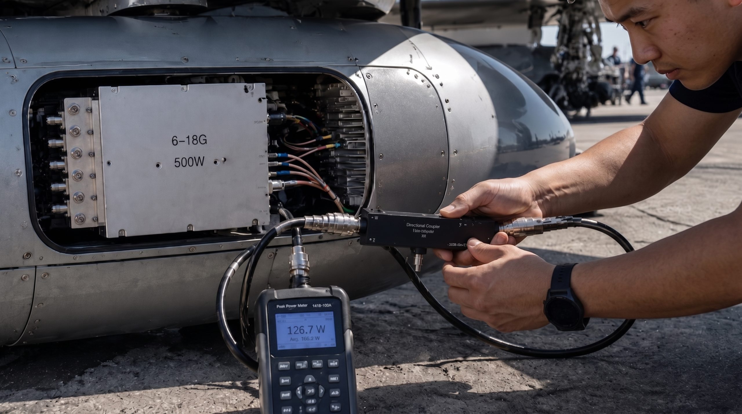
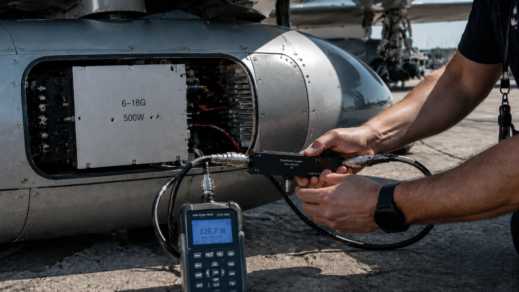
Airborne EW pods face severe operational stresses during flight tests. Technicians often encounter sudden telemetry drops at 15,000 feet. Ground stations display severe spectral regrowth alongside abnormal noise floors. Transmitted power drops abruptly across upper frequency bands. We pull our compact assembly onto a tarmac for immediate inspection. You connect one inline directional coupler plus a peak power meter. Five minutes of continuous wave transmission causes massive output sagging. Output drops rapidly from 500W down toward 250W. System management buses flag internal thermal alarms immediately. Ambient temperatures remain completely normal during this entire testing phase. Most field engineers suspect degraded GaN transistors or burned matching capacitors. They pull faulty modules out quickly for factory returns. This wastes two weeks of critical project time unnecessarily. Stop replacing hardware before checking baseplate mounting screws properly. Nine times out of ten failures involve simple mechanical mistakes. Technicians tighten mounting screws sequentially rather than applying strict diagonal patterns. Uneven clamping forces create microscopic deformations across copper bases. What’s the real story? We must trace physical realities behind these alarming system level failures.
Use high-VSWR thermal test findings to shortlist RF hardware
High-VSWR thermal testing should feed back into amplifier protection, heat sinking, antenna matching, RF front-end layout and acceptance criteria. CorelixRF can review these requirements before quote stage.
Using Inline Directional Couplers For Diagnosis
Field troubleshooting requires objective measurement tools rather than blind guessing. You must place an inline directional coupler between our amplifier output and antenna load. This setup captures both forward and reflected waves accurately. We connect an oscilloscope alongside our spectrum analyzer for deep analysis. We observe anomalous standing waves appearing suddenly under high power states. Reflected signals trigger repeated VSWR alarms on our system displays. Screen warnings flash red indicating mandatory power reduction protocols. Operators watch helpless as mission critical jamming capabilities vanish instantly. This failure mode only happens inside highly constrained pod structures. Generic laboratory testing rarely exposes such specific mechanical design flaws. We recreate these identical conditions using high vibration tables. Our tests reveal shocking details about thermal interface behaviors. Here’s the deal. Standard aluminum cold plates flex slightly under uneven torque stress. Microscopic gaps form directly beneath highest heat generating components. These invisible voids cause immediate catastrophic thermal runaway events. We will analyze exact thermodynamic principles behind such catastrophic breakdowns next.
| Failure Mode | Symptom | Immediate Action |
| Telemetry Drop | Signal loss | Pull pod for tarmac inspection |
| Power Sagging | Output halves after 5 mins | Connect inline directional coupler |
| VSWR Alarms | High reflected waves | Check thermal interface mechanics |
| Spectral Regrowth | Abnormal noise floor | Analyze baseplate deformation |
2. How Does Uneven Torque Cause Micro-Gaps And Thermal Impedance?
The Fulcrum Effect On Baseplate Deformation
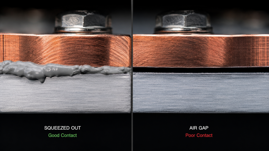
Rigid RF power modules rely exclusively upon conduction cooling techniques. Heat transfers directly from device packages into surrounding metal cold plates. Fastening rigid assemblies demands precise mechanical sequencing during field installations. Technicians who torque screws using circular patterns cause immediate structural bending. Screwing down corner one then two establishes an improper anchor line. Applying force upon corner three acts like pushing a lever arm. This action lifts opposite corners creating severe mechanical fulcrum effects. The baseplate undergoes microscopic bending forces exceeding specified material tolerances. We measure these deformations using high precision laser topography scanners. Deflections measuring only fifty microns destroy carefully calculated thermal budgets completely. . You might be wondering. Why does such tiny deflection matter inside rugged military hardware? High power density demands perfectly flat mating surfaces for heat transfer. Air holds notoriously poor thermal conductivity compared against standard metallic conductors. Any trapped atmosphere blocks energy flow moving away from sensitive dies. Next we examine how thermal interface materials degrade under these specific conditions.
TIM Pump-Out And Air Gap Insulation
Thermal interface materials fill microscopic imperfections between mating metal surfaces. Uneven clamping forces pinch these delicate compounds completely out from one side. This aggressive squeezing action leaves bare metal grinding against bare metal. Simultaneously a microscopic air gap forms across the opposite lifted section. Thermal conductivity of air measures roughly 0.026 watts per meter Kelvin. Standard silicone pads provide between three and five watts per meter Kelvin. This massive discrepancy turns trapped air into an absolute thermal insulator. Heat backs up rapidly behind this invisible barrier within seconds. We observe localized heat fluxes exceeding 100 watts per square centimeter. Junction temperatures skyrocket far beyond safe operational margins very quickly. Traditional junction temperature calculations break down entirely under these abnormal scenarios. The assumed thermal resistance value reaches near infinity across vacuum pockets. This is where it gets interesting… Our engineering team simulated this exact failure mode inside vacuum chambers. The resulting thermal map showed catastrophic hot spots directly above loose screws. Gallium Nitride devices simply cannot survive such extreme concentrated thermal abuse.
| Material | Thermal Conductivity (W/m·K) | Heat Transfer Capability |
| Trapped Air | 0.026 | Insulator |
| Standard TIM | 3.0 – 5.0 | Acceptable |
| CRF Precision Base | > 300 | Superior |
3. Why Do VNA Curves Collapse Under Junction Temperature Runaway?
Electron Mobility Plummets In GaN Channels
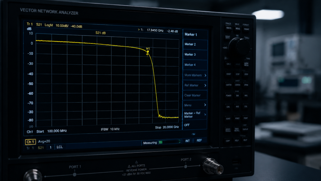
Junction temperatures rising past 200 degrees Celsius trigger severe semiconductor physics changes. Electron mobility inside Gallium Nitride channels plummets at extreme heat levels. This physical reality manifests outwardly as severe gain compression rapidly. Engineers notice S21 magnitude sagging heavily on their network analyzers. Target output power levels fail dropping well below specified 500W thresholds. The amplifier begins drawing excessive direct current attempting compensation futilely. Increased current draw generates even more heat accelerating this deadly cycle. . We call this phenomenon thermal runaway within microwave engineering circles. The active device structure degrades physically leading toward permanent catastrophic failure. Ready for the good part? Understanding these physical mechanisms allows us to design better protective circuits. We must prevent internal dies from reaching these destructive temperature limits. Most competitor designs lack adequate localized sensing mechanisms near final stage transistors. They rely upon generic external chassis sensors arriving too late. CorelixRF measures temperature directly adjacent beside individual high power semiconductor components. This tight proximity guarantees nanosecond reaction times when localized overheating occurs.
Dielectric Constant Shifts In High-Frequency Substrates
Extreme localized heating damages more than just active semiconductor elements. High frequency printed circuit boards utilize specialized materials like Rogers substrates. These advanced composite structures possess highly sensitive temperature coefficients naturally. Intense heat causes physical expansion altering their fundamental dielectric constants significantly. Changing dielectric constants detunes carefully crafted high frequency matching networks immediately. This physical alteration explains why VNA curves collapse abruptly at upper bands. Signals operating near 18,000 MHz experience massive impedance mismatches suddenly. Power reflects backward toward driver stages rather than propagating outward. Intermodulation distortion worsens visibly across connected spectrum analyzer screens. System level performance drops below acceptable military specifications rendering jamming useless. But here’s the kicker Once temperatures return normal these substrates might not recover fully. Repeated thermal cycling causes permanent delamination within multi-layer board structures. Field repairs become impossible requiring complete module replacements at huge costs. We solve this by engineering robust mechanical structures preventing initial uneven heating entirely.
| Component | Heat Impact | RF Symptom |
| GaN Transistor | Electron mobility drops | S21 gain compression |
| PCB Substrate | Dielectric constant shifts | VNA curve high-frequency collapse |
| Matching Network | Impedance mismatch | VSWR alarms trigger |
4. How Do High-Frequency Vibrations Exacerbate Thermal Failures?
Micro-Arcing And Floating RF Grounds
Airborne compact pods endure intense high frequency vibrations during operational flights. These violent mechanical forces shake every internal component mercilessly. An unevenly clamped baseplate chatters aggressively against its mounting cold plate. This rapid separation creates dangerous micro arcing across mating metal surfaces. Poor physical contact leads directly toward floating radio frequency ground planes. Unstable ground references inject massive wideband noise into output signals. Our engineers measure this noise using high end phase noise analyzers. The resulting spectrum shows elevated noise floors obscuring target radar signatures. What’s the catch? Standard laboratory testing often misses these dynamic operational factors entirely. Engineers testing on static benches see perfect signal clarity misleadingly. You must simulate actual flight vibration profiles while operating amplifiers fully. This reveals hidden mechanical weaknesses within low cost commercial module designs. CorelixRF conducts extensive MIL-STD vibration testing ensuring absolute mechanical integrity under stress. A perfectly flat rigidly mounted baseplate prevents all high frequency chattering.
Wideband Noise Injection Into Spectrum Analyzers
Vibration induced grounding issues create cascading failures across entire radar systems. Receivers connected nearby pick up massive wideband noise injections easily. This interference destroys receiver sensitivity blinding sensitive target tracking algorithms. System integrators spend weeks debugging software believing their algorithms failed. They rarely suspect mechanical baseplate chattering causing such complex electromagnetic interference. We provide specialized training helping field engineers identify these specific mechanical signatures. Using fast fourier transform techniques reveals distinct vibration frequency peaks clearly. Matching these electrical peaks against known mechanical resonance frequencies confirms our diagnosis. Let us explore further. Fixing this requires replacing faulty modules and applying correct installation procedures. Technicians must clean all mating surfaces removing debris before applying fresh paste. Following exact torque specifications using calibrated tools prevents recurring failures permanently. We engineered our products anticipating these precise frontline maintenance challenges.
| Profile | Condition | Expected Result |
| Random Vibration | 20-2000 Hz | Zero structural chatter |
| Shock Testing | 30G peak | No micro-arcing |
| Thermal Cycling | -40 to +85 Celsius | Maintained ground integrity |
5. What Is The CorelixRF Solution For Mechanical Failures?
Introducing The CRF-PA-6000M18000M-500W
We engineer solutions targeting root physical causes behind system failures directly. CorelixRF designed the CRF-PA-6000M18000M-500W specifically for severe pod integrations. This model delivers 500W rated output power across wideband frequency ranges. It operates flawlessly between 6,000 and 18,000 MHz without compromise. We maintain strict engineering truth rejecting flashy marketing claims entirely. You get exactly what our data sheets promise under actual field conditions. Our hardware utilizes advanced Gallium Nitride technology maximizing efficiency and durability. The AC 380V power supply handles immense current requirements stably. Here is the truth. We observed too many integrators failing due to poor mechanical practices. Providing great electrical specifications means nothing if mechanical installations ruin performance. Our Full Power Series addresses these exact structural vulnerabilities proactively. Every module ships with built in physical defenses against technician errors. This rugged design saves massive troubleshooting time during complex system deployments.
Precision CNC-Machined Baseplate Topography
Most commercial amplifiers utilize cheap stamped or extruded aluminum baseplates. These low cost manufacturing methods leave microscopic waves across mating surfaces. CorelixRF strictly forbids using such inferior materials inside our high power modules. We CNC machine every baseplate directly from solid oxygen free copper blocks. Our precision milling processes maintain absolute flatness tolerances below 0.02 millimeters. This extreme rigidity resists deformation even if technicians apply uneven torque momentarily. The thick metal mass acts as an exceptional thermal spreader instantly. Localized hot spots dissipate horizontally before reaching dangerous junction temperature thresholds. You cannot ignore this. Achieving a 57 dB gain requires massive internal heat generation constantly. Only perfect physical contact against cold plates removes this thermal energy safely. We inspect every finished baseplate using optical interferometry verifying absolute flatness. Our meticulous quality control ensures maximum heat transfer capability out of the box. Integrators trust our hardware when building mission critical electronic warfare pods.
6. How Does The CRF-PA-6000M18000M-500W Prevent Thermal Damage?
Hardware-Level Over-Temperature Protection
Mechanical perfection offers primary defense but we demand secondary electronic safeguards. If air gaps occur our module must protect itself before permanent degradation. The CRF-PA-6000M18000M-500W incorporates advanced built in protection circuits automatically. These systems monitor baseplate temperatures via highly calibrated internal thermistors continuously. We place these sensors immediately adjacent beside final stage Gallium Nitride transistors. When junction temperatures breach safe thresholds our control board reacts instantly. The module enacts nanosecond level current foldback capping maximum power draw. Power throttles down gracefully rather than burning delicate internal components violently. This changes everything. Field technicians receive visual alarms via LAN or RS485 control interfaces. They can halt testing safely before expensive RF hardware suffers permanent damage. The system recovers fully once operators correct external cooling faults properly. We provide complete fault logs helping engineers analyze failure timelines accurately. This transparency builds massive trust between our engineering team and system integrators.
VSWR Survival And Current Foldback Mechanisms
Uneven heating detunes matching networks causing massive internal standing wave ratios. Power reflects back directly into fragile final stage transistor drains aggressively. Standard amplifiers explode under such extreme mismatched load conditions very quickly. Our Full Power Series survives total mismatch scenarios without sustaining any damage. The CRF-PA-6000M18000M-500W handles severe VSWR conditions using advanced isolator designs. Our input VSWR remains strictly below 1.5:1 under all operating states. Reverse power detectors measure reflected energy triggering protection protocols within microseconds. The current foldback mechanism limits DC power preventing dangerous voltage spiking. Why does this matter? Antennas mounted upon compact pods often suffer physical battle damage. A broken antenna creates an infinite standing wave ratio instantly. Our amplifier survives this event maintaining readiness until technicians replace damaged antennas. This resilience defines true military grade engineering truth over commercial approximations. CorelixRF builds hardware designed for actual chaotic battlefield realities always.
| Protection Type | Trigger Condition | System Response |
| Over-Temperature | Baseplate > Safe Limit | Current foldback / Power down |
| VSWR Mismatch | High reflected power | Fast shutdown |
| Over-Drive | Input > Threshold | Gain compression |
| Over-Voltage | Supply spike | Power supply isolation |
7. Why Are Specific Torque Yields Critical For RF Amplifiers?
Eliminating Human Error On The Tarmac
We must eliminate human error completely during high pressure tarmac maintenance. Technicians rushing under harsh weather conditions make simple installation mistakes frequently. Memorizing complex torque sequences for dozen different modules remains highly impractical. We studied numerous field failure reports documenting improper screw tightening procedures. The data clearly showed sequential tightening causing most mechanical baseplate failures. Applying uneven forces ruins carefully applied thermal interface material layers instantly. We needed a foolproof method guaranteeing correct installation without requiring thick manuals. Here is the secret. We embed mandatory mechanical instructions directly onto our product hardware. You cannot install our amplifiers without seeing proper tightening sequences prominently displayed. This visual guidance forces technicians toward correct diagonal cross pattern techniques naturally. We specify exact torque yield values preventing both under and over tightening. Proper clamping force ensures ideal thermal paste thickness across entire mating surfaces.
Laser-Etched Mechanical Instructions
Our manufacturing process includes laser etching mechanical instructions directly upon housings. The diagonal torque sequence numbers appear visibly beside every mounting hole. We clearly engrave exact torque specifications alongside these prominent directional arrows. A technician simply follows etched numbers matching one towards three then two towards four. This permanent marking survives harsh chemical washes and intense physical abrasions. We eliminated paper stickers which peel away rapidly during harsh operational deployments. Want to know the best part? This simple mechanical innovation reduces field thermal failures almost entirely. System integrators report massive drops regarding false hardware failure returns post adoption. Less returned hardware means lower lifetime support costs across major defense programs. We believe true engineering truth encompasses both advanced electronics and idiot proof mechanics. CorelixRF continuously improves these small details maximizing overall system reliability drastically. We protect your investment through thoughtful ruggedized physical design choices always.
8. How To Verify Proper Heat Dissipation With Peak Power Meters?
Continuous Wave Transmission Testing
Engineers must verify proper thermal dissipation immediately after installing new modules. You cannot rely upon short burst pulse testing for thermal validation. Pulse testing hides severe cooling issues due to low average power. We mandate continuous wave transmission testing using inline peak power meters. Connect a calibrated N-Female cable directly into our amplifier input port. Drive the system using a high quality laboratory signal generator securely. Monitor output via the WRD650 waveguide interface connecting high power attenuators. Engage continuous wave mode holding 500W output for thirty minutes minimum. Are you paying attention? This sustained test forces thermal equilibrium across entire mechanical assemblies. Any hidden air gaps will manifest quickly as rapidly rising baseplate temperatures. Watch your monitoring software closely for any sudden automated protection triggers. A properly installed CorelixRF module handles this extreme test effortlessly without alarms.
Monitoring Output Power Sag
Peak power meters provide precise visibility into hidden thermodynamic system failures. You must observe output power readings meticulously during continuous wave tests. A perfectly cooled GaN amplifier maintains steady output power indefinitely. If baseplate screws remain loose thermal resistance increases driving temperatures upward. Rising junction temperatures cause electron mobility drops creating visible power sagging. You might watch 500W output slowly drop toward 480W then 450W steadily. This slow degradation confirms poor thermal interface contact definitively without guessing. Here is the reality. Never accept power sagging as normal behavior inside professional RF systems. True engineering truth dictates absolute stability under specified operational temperature ranges. If power sags you must pull the module and check mounting screws. Clean off old thermal paste thoroughly before applying fresh precise layers. Retorque following our laser etched diagonal instructions exactly using calibrated wrenches. Retest continuously until output power remains absolutely flat across extended timeframes.
9. What Are The Key Electrical Characteristics Of The Full Power Series?
Analyzing The 6,000 – 18,000 MHz Frequency Range
The CRF-PA-6000M18000M-500W covers immense bandwidth targeting sophisticated electronic warfare applications. Operating between 6,000 and 18,000 MHz requires extraordinary microwave engineering skill. Maintaining flat gain across this massive spectrum challenges traditional amplifier designs. Our engineers achieved a remarkable gain flatness of plus or minus 6 dB. This wideband capability allows single pods to jam multiple enemy radar bands simultaneously. We utilized advanced spatial combining techniques minimizing internal insertion losses greatly. Superior matching networks maintain excellent input standing wave ratios across all frequencies. A strict 1.5:1 VSWR ensures maximum power transfer from upstream driver stages. What does this mean for you? You replace multiple narrowband amplifiers using one single highly reliable module. This reduces total pod weight saving precious airborne payload capacity significantly. Simplifying system architecture inherently improves overall mean time between failures. CorelixRF delivers uncompromising performance backed by rigorous physical test data always.
Evaluating The 500W Rated Output Power
Generating 500 watts of continuous radio frequency energy requires serious hardware. Our module achieves this output while maintaining exceptionally clean spectral purity. We specify harmonics strictly between minus 15 and minus 8 dBc. The noise floor remains suppressed below minus 25 dBm per MHz consistently. Spurious emissions stay firmly below minus 60 dBc preventing unwanted system interference. Achieving these numbers requires massive amounts of clean DC electrical current. Our AC 380V power supply feeds internal switching regulators highly efficiently. High efficiency reduces total thermal loads manageable by built in air cooling. This is the bottom line. Real 500W performance demands perfect harmony between electrical and mechanical engineering. A poorly cooled GaN transistor cannot sustain such extreme power levels safely. We guarantee our specifications because we solved fundamental physical cooling challenges first. Our rigorous engineering truth approach produces hardware you can trust absolutely.
10. How Can Integrators Optimize System Level Thermal Dissipation?
Conducting Comprehensive Thermal-Mechanical Reviews
System integrators face daunting challenges packing high power electronics into tight spaces. You cannot simply bolt modules down hoping internal fans provide enough cooling. Airflow inside compact pods behaves unpredictably requiring advanced computational fluid dynamics analysis. CorelixRF offers comprehensive thermal mechanical review services supporting your engineering teams directly. We analyze your specific cold plate designs recommending optimal mounting strategies confidently. Our application engineers share decades of frontline troubleshooting experience freely with clients. We help identify potential vibration nodes preventing destructive mechanical resonance frequencies. Let me be clear. Partnering early during design phases prevents catastrophic failures during late stage testing. We review your thermal interface material selections ensuring adequate heat transfer capabilities. Our team verifies your fastener choices recommending specific aerospace grade hardware options. This collaborative approach guarantees maximum performance from our Full Power Series amplifiers.
Requesting Engineering Data Sheets
Stop losing high value modules due toward simple mechanical mounting errors today. Understanding physical realities separates successful deployments from costly engineering disasters completely. We document every technical parameter meticulously within our official product documentation. CorelixRF provides extensive test data and pattern files for detailed project reviews. Our hardware meets strict CE FCC ISO 9001 and GJB 9001C compliances. You deserve complete transparency when selecting military grade radio frequency power components. Your next step is simple. Contact our technical marketing department requesting complete CRF-PA-6000M18000M-500W data sheets immediately. Evaluate our mechanical outlines confirming easy integration into your existing pod architectures. Discuss optional forward reverse power monitoring features with our sales engineers today. Demand genuine engineering truth over empty commercial marketing promises from your suppliers. We build RF hardware designed surviving the harshest physical realities imaginable continuously.
Conclusion
Mechanical installation errors ruin superior radio frequency hardware performance instantly. Proper diagonal screw torqueing prevents disastrous thermal runaway inside compact pods. We engineered the CRF-PA-6000M18000M-500W Full Power Series mitigating these physical risks entirely through precision machining. Choose CorelixRF for absolute engineering truth regarding your high power microwave system integrations today.
FAQ
Q1: What is thermal runaway in GaN power amplifiers?
Thermal runaway occurs when high temperatures reduce electron mobility causing massive heat generation. This rapidly destroys internal components without built-in over-temperature protection.
Q2: How does uneven screw torqueing cause signal anomalies?
Uneven torque bends the amplifier baseplate creating microscopic air gaps. These gaps act as insulators causing localized overheating and severe RF gain compression.
Q3: Why do VNA curves collapse at high frequencies during overheating?
Extreme heat alters the dielectric constant of specialized high-frequency PCB substrates. This immediately detunes matching networks causing massive impedance mismatches and curve collapse.
Q4: How does the CRF-PA-6000M18000M-500W prevent thermal damage? It uses precision CNC-machined copper baseplates resisting mechanical deformation. Built-in thermistors trigger nanosecond current foldback protection if junction temperatures breach safe operational limits.
Q5: What are the consequences of high-frequency vibration on loose baseplates?
Vibration causes loose baseplates to chatter against cold plates creating micro-arcing. This produces floating RF grounds injecting massive wideband noise into the transmitted spectrum.