
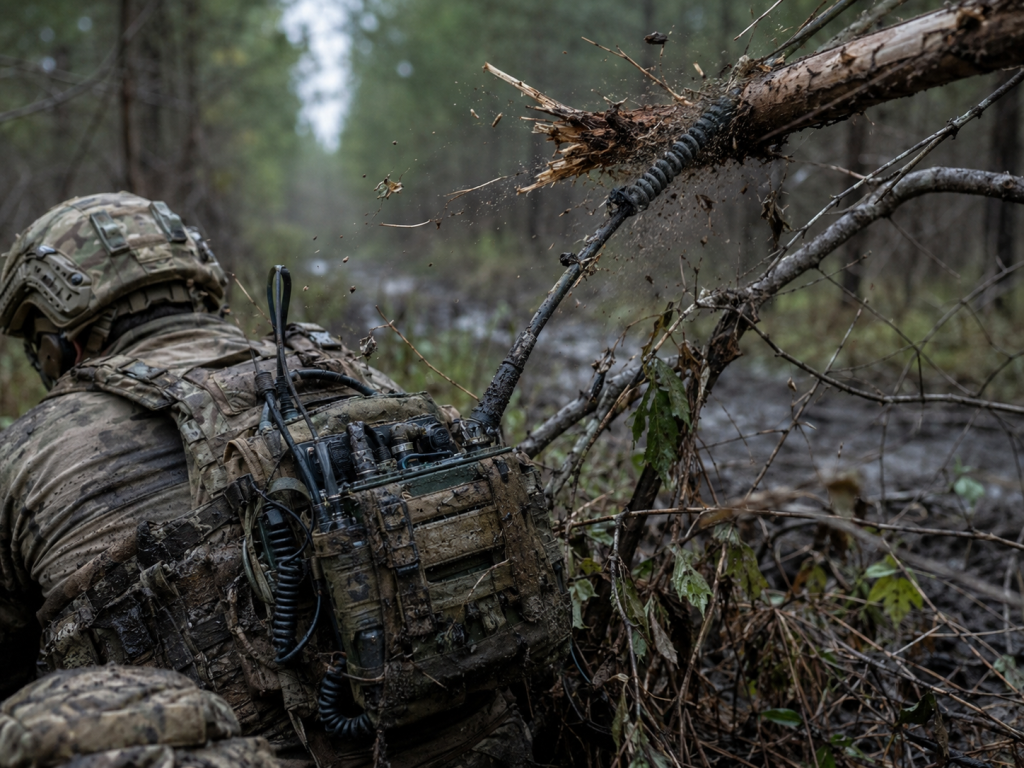
Frontline communications demand absolute reliability under extremely harsh tactical conditions. Operators frequently report sudden system alarms indicating severe output power degradation mid-mission. Such failures usually stem from accidental antenna snapping during infantry movements through dense foliage. Broken antennas cause massive mismatched impedance. Mismatched loads force standing waves back down coaxial transmission lines. Reflected microwave energy hits final-stage transistors directly. Those gallium nitride transistors absorb enormous unnatural thermal spikes immediately. Component destruction follows rapidly without robust VSWR protection mechanisms. CorelixRF engineered a specific 100W module addressing these exact mechanical vulnerabilities comprehensively. Our extensive troubleshooting background spanning two decades informs every architectural decision inside these robust wideband modules. We routinely analyze returned field hardware exhibiting catastrophic die burn-out. Replacing fragile commercial amplifiers with our CRF-PA-30M512M-100W eliminates typical operational dread. Rely on genuine engineering truth for resilient tactical deployments.
1. Why Do Infantry Radios Experience Sudden Power Degradation?
Tactical environment realities
Physical impact consequences
Hidden signal reflections
You might be wondering why ruggedized military transceivers suddenly drop transmission range completely during active firefights. Infantrymen crawl through muddy trenches carrying heavy manpack radios daily. Antennas violently strike rocks alongside armored vehicle hatchways continuously. These aggressive physical impacts frequently break internal matching coils hidden inside flexible whip antennas. Undetected micro-fractures sever internal connections entirely. This open circuit creates an infinite standing wave ratio instantly. Forward transmitting power reaching that fracture bounces backwards towards your source stage. A 100W output signal travelling backward acts like one microwave weapon focused directly upon internal amplifier die structures. Traditional silicon LDMOS devices cannot dissipate such extreme localized heating quickly enough. Fast thermal gradients crack delicate semiconductor junctions permanently. We see these exact failure signatures using high-resolution infrared microscopy across many generic returned units. Routine diagnostic routines miss these subtle faults completely because static bench tests rarely simulate violent battlefield shocks.
Typical Infantry Radio Antenna Damage Modes
| Damage Type | Physical Cause | Electrical Consequence | Field Diagnostic Symptom |
| Base Coil Snap | Vehicle hatch impact | Infinite VSWR (Open) | Immediate range drop |
| Element Micro-fracture | Heavy foliage snagging | Intermittent impedance shift | Spurious noise bursts |
| Connector Shearing | Rifle stock collision | Short circuit | Overcurrent alarm |
2. How Does Antenna Damage Trigger Reflected Energy Backflow?
Impedance mismatch mechanics
Transmission line theory
Standing wave formation
Let us dig a little deeper into specific electromagnetic mechanisms governing reflection coefficients within damaged radio front-ends. Any 50-ohm transmission system requires perfect load matching for optimal energy transfer. Snapping an antenna element instantly changes terminal impedance from fifty ohms towards several thousand ohms. Microwave energy traveling outward hits this boundary abruptly. Physics dictates that unabsorbed energy must reverse direction immediately. High-power waves collide against forward-moving signals creating massive voltage standing waves. Peak voltage nodes multiply normal operating potentials by enormous factors. These elevated voltages exceed transistor breakdown thresholds instantly. Arc-overs vaporize delicate gold wire bonds connecting internal die segments. We utilize network analyzers routinely measuring severely degraded return loss profiles on damaged gear. Observing S11 parameter charts reveals catastrophic shifting away from center chart regions entirely. Technicians measuring these return paths notice severe Smith chart looping across multiple MHz bands.
3. What Causes Thermal Runaway During Tactical Maneuvers?
Continuous wave transmission
Reflected power dissipation
Semiconductor heating curves

But wait, here lies the kicker regarding invisible destructive forces targeting active semiconductor junctions during extended deployment cycles. Forward operators often key their handsets continuously calling artillery support under heavy suppression fire. Prolonged continuous wave transmission generates substantial baseline heat requiring efficient dissipation. Adding severe reflected power atop this thermal baseline pushes junction temperatures past safe operating limits quickly. Gallium Nitride devices possess negative temperature coefficients concerning carrier mobility. As channels heat uncontrollably, internal resistance rises sharply. Rising resistance generates additional localized heating creating one vicious cycle. This phenomenon constitutes classic thermal runaway leading directly toward spontaneous device destruction. Analyzing damaged circuitry reveals melted solder joints beneath main power transistors. Poor thermal interfacing accelerates this breakdown cascade significantly. Field conditions rarely allow adequate cooling airflow around sealed manpack chassis structures. Ambient desert temperatures further erode available thermal margins drastically. System integrators must assume worst-case environmental heating continuously.
Junction Temperature Impact on Transistor Lifespan
| Baseplate Temp (°C) | Internal Junction Temp (°C) | Estimated MTBF (Hours) | Failure Mode Probability |
| 65 | 115 | >1,000,000 | Nominal wear |
| 85 | 145 | 250,000 | Accelerated aging |
| 105 | 185 | <1,000 | Rapid thermal decay |
4. Why Does Uneven Baseplate Tightening Lead Toward Early Device Failure?
Mechanical torque specifications
Thermal interface gaps
Heat transfer efficiency
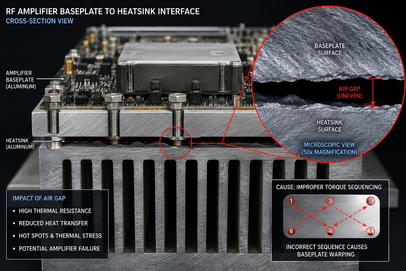
Now, pay close attention regarding proper mechanical assembly techniques governing amplifier installation within host chassis enclosures. Junior technicians occasionally rush equipment assembly under severe time constraints. Fastening mounting screws sequentially clockwise rather than utilizing one strict diagonal torque pattern warps that entire module baseplate. Such microscopic bowing creates invisible air gaps between your amplifier floor and its corresponding heat sink surface. Air acts like an excellent thermal insulator blocking conductive heat transfer completely. Model CRF-PA-30M512M-100W generates intense concentrated heat requiring absolute physical flatness against its mating surface. Even tiny voids measuring fractions of a millimeter disrupt continuous thermal flow paths. High-power sections positioned above these voids experience accelerated localized heating immediately. This specific assembly error causes premature power degradation indistinguishable from pure electrical overstress failures. Adhering toward fundamental mechanical discipline prevents countless unexplained field malfunctions permanently. Applying thermal compound haphazardly exacerbates poor mechanical mating further.
5. How Do We Use VSWR Meters For Frontline Diagnostics?
Directional coupler functionality
Forward power measurement
Reflected power calculation
Here lies an interesting facet concerning practical frontline troubleshooting protocols during active deployments. Forward operating bases require rugged test equipment capable of measuring complex impedance characteristics quickly. Inline VSWR meters provide immediate visibility regarding antenna health status. Inserting one directional coupler between radio output ports and antenna feeds reveals forward alongside reflected wattages. High reflected readings indicate catastrophic transmission line compromises immediately. We frequently train soldiers regarding proper interpretation of these analogue meter sweeps. Seeing 100 watts going forward paired against 50 watts reflecting backward demands immediate transmission cessation. Using portable oscilloscopes paired alongside RF detectors visualizes transient voltage spikes destroying final output stages. These practical measurement skills separate seasoned engineers from novice operators struggling with recurring equipment failures. Identifying damaged coaxial cables takes minutes using basic reflectometry principles properly applied.
Field VSWR Troubleshooting Matrix
| Measured VSWR | Reflected Power % | Diagnostic Conclusion | Recommended Action |
| 1.0:1 | 0.0% | Perfect Match | Continue normal operations |
| 1.5:1 | 4.0% | Acceptable Load | Monitor periodically |
| 3.0:1 | 25.0% | Serious Degradation | Inspect antenna connections |
| >10:1 | >80.0% | Open/Short Circuit | Cease transmission instantly |
6. What Hardware Safeguards Prevent These Catastrophic Scenarios?
Isolator integration limits
Fast-acting VSWR detection
Automatic power rollback
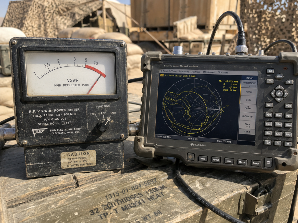
You might be wondering exactly what specific internal hardware modifications protect expensive amplifier modules from such harsh treatment. Traditional narrowband communication systems often employ heavy magnetic ferrite isolators absorbing reflected energy safely. However, designing true wideband isolators covering 30-512 MHz frequencies proves physically impossible due toward fundamental magnetic material limitations. Modern broadband architecture demands active closed-loop electronic protection mechanisms instead. Sophisticated micro-directional couplers sample outgoing waveforms continuously sensing reverse voltage thresholds instantly. Fast analog comparator circuits trigger deep gain attenuation sequences within microseconds following severe mismatch detection. Pulling bias voltage away from final transistors throttles current consumption immediately preventing thermal runaway completely. Designing these ultra-fast protection loops requires mastering parasitic inductance management across complex multilayer printed circuit boards. CorelixRF engineers spent years perfecting these exact hardware tripwires ensuring maximum survivability. Only specialized high-speed sensing circuits react quickly enough preserving delicate semiconductor junctions.
7. How Does CRF-PA-30M512M-100W Handle High VSWR Conditions?
Datasheet anchoring
Current consumption limits
Ruggedized architecture
Here lies our reality concerning our flagship CRF-PA-30M512M-100W module specifically designed for hostile tactical environments. According toward official CorelixRF specification sheets, this unit delivers 100W saturated output power requiring 28 VDC nominal supply voltage. We strictly mandate maximum current consumption remaining below 18 Amperes under worst-case operational modes. When infantry antennas break unexpectedly, internal active protection engages clamping drain currents tightly. This module tolerates severe output VSWR conditions reaching 2.0:1 continuously without suffering any parametric degradation whatsoever. Furthermore, robust SMA-Female input alongside N-Female output connectors guarantee superior mechanical rigidity during violent vehicle maneuvers. Maintaining input drive levels near 0 dBm yields an impressive 50 dB nominal gain profile flawlessly. Every unit undergoes rigorous thermal cycling spanning -40°C through +85°C ensuring military-grade reliability. Field proven ruggedness defines our engineering philosophy completely.
CRF-PA-30M512M-100W Critical Engineering Parameters
| Parameter | Min | Typ | Max | Units |
| Frequency Range | – | 30-512 | – | MHz |
| Output Power | 100 | 100 | – | W |
| Gain | 49 | 50 | 51 | dB |
| Current Consumption | – | – | $\le18$ | A |
| Output VSWR Tolerance | 1.5 | – | $\le2.0$ | :1 |
8. Why Does Wideband Matching Matter Between 30-512 MHz?
Multi-octave challenges
Harmonic suppression
Gain flatness
Ready for one fantastic revelation? Designing matching networks covering multiple octaves across 30-512 MHz presents extreme mathematical challenges. Infantry radios utilize frequency hopping protocols necessitating instantaneous impedance matching across vast spectrum widths. Traditional single-stage matching fails entirely attempting broad bandwidth coverage. We utilize advanced spatial combining architectures leveraging specialized planar transformers built directly into high-frequency circuit boards. This approach guarantees remarkable gain flatness strictly remaining below $\le1.8$ dB across all frequencies. Maintaining strict input VSWR parameters around 1.3:1 typical ensures perfectly transparent interfacing with pre-driver stages. Without precise multi-octave matching, severe power slumps occur during specific frequency hops creating dead zones geographically. Our engineering team meticulously tunes every production unit mitigating spurious emissions strictly below $\le-60$ dBc consistently. Harmonics remain tightly controlled meeting $\le-10$ dBc specification minimums effortlessly. Such uncompromising electrical purity prevents fratricide interference among collocated friendly communication nodes perfectly.
9. How Should Field Technicians Properly Install High-Power RF Modules?
Mechanical torque sequencing
Package size considerations
Heat dissipation strategy
What lies behind preventing mechanical failures during field integration procedures? Technicians must handle heavy metal packages measuring precisely 200\times158\times25~mm deliberately. Weighing approximately \le1.4 kg, these modules require robust mounting frameworks accommodating severe shock loading. We strictly advise applying high-quality thermal interface materials evenly across entire baseplate surfaces using specialized spreading tools. Personnel must tighten all mounting screws following alternating diagonal sequences preventing microscopic structural bowing completely. Utilizing calibrated torque wrenches guarantees uniform compression avoiding localized stress concentrations entirely. Never overtighten connectors attaching heavy coaxial cables onto delicate SMA or N-type chassis mounts. Installing massive heatsinks equipped with high-velocity forced air cooling fans remains an absolute necessity. Operating naked modules without adequate airflow destroys expensive components within minutes regardless regarding built-in electronic protections. Proper mechanical discipline saves immense logistical replacement costs downrange.
Mechanical Installation Best Practices
| Action Item | Method/Tool | Target Specification | Reason |
| Baseplate Mating | Diagonal Torque Pattern | Zero Air Gaps | Prevents thermal decay |
| Fastener Tightening | Calibrated Torque Wrench | 1.5 Nm | Avoids casing warpage |
| Weight Support | Shock Mount Dampeners | Support $\le1.4$ kg | Reduces vibrational stress |
| Clearance | Chassis Design | Fit 200\times158\times25~mm | Guarantees proper airflow |
10. What Are Immediate Action Steps Following System Alarms?
Diagnosis workflow
Power isolation
System resetting
Everything boils down toward this regarding swift response protocols whenever high VSWR alarms sound mid-operation. Operators must immediately cease transmitting avoiding further thermal accumulation inside stressed amplifier stages. Disconnecting main 28 VDC power supplies prevents accidental rekeying while troubleshooting ongoing hardware faults. Technicians should systematically inspect entire antenna feedlines checking physical integrity concerning every connector junction. Replacing suspected damaged whip antennas prior toward resuming transmission eliminates major fault sources instantly. Measuring return loss using portable network analyzers verifies repaired transmission line impedance conclusively. Once verified perfectly matched, engineers may reapply primary power monitoring quiescent current draw carefully. Any abnormal baseline current exceeding a few amperes indicates permanent internal component degradation requiring module replacement. CorelixRF designs resilient systems surviving multiple abuse cycles however physical laws dictate eventual limits. Rigorous training ensures frontline personnel manage these technological boundaries effectively.
Understanding frontline thermal dynamics alongside reflected energy mechanisms allows integrators creating indestructible tactical communications. Proper diagonal baseplate mounting paired alongside continuous VSWR monitoring prevents catastrophic battlefield failures entirely. Contact our CorelixRF engineering team today reviewing comprehensive CRF-PA-30M512M-100W documentation ensuring your next radio deployment survives absolute worst-case combat scenarios flawlessly.
FAQ Section
Q1: What is thermal runaway inside RF amplifiers?
Thermal runaway occurs whenever excessive heat increases internal semiconductor resistance rapidly. Rising resistance generates additional heat creating one unstoppable destructive cycle melting internal wire bonds.
Q2: How does an open circuit cause amplifier damage?
Broken antennas create infinite standing wave ratios instantly reflecting forward energy backwards. This reflected power multiplies internal voltages exceeding transistor breakdown limits causing permanent destruction.
Q3: Why must technicians use diagonal torque patterns?
Sequential tightening warps aluminum baseplates creating microscopic air gaps. Air blocks heat transfer causing localized high-power transistor overheating leading toward premature optical decay.
Q4: What specific frequency range does Model CRF-PA-30M512M-100W cover? Our rugged module covers broadband frequencies spanning 30-512 MHz continuously. Delivering steady 100W output requires no internal switching mechanisms during fast tactical frequency hops.
Q5: How do isolators differ from active electronic protection loops?
Traditional magnetic isolators absorb reflected waves safely however they cannot cover multi-octave bandwidths physically. Active protection circuits monitor reverse voltages throttling supply currents instantaneously.
Turn VSWR behavior into factory acceptance evidence
High VSWR protection should be defined with mismatch scenario, foldback or shutdown threshold, recovery logic, alarm output, thermal limit and FAT evidence. This makes protection claims measurable for procurement.
Recommended next step: send the operating band, output power target, duty cycle, load condition, control interface, protection or thermal limits and required FAT documents. CorelixRF can review this How to Prevent Thermal Runaway: RF Amplifier High VSWR Troubleshooting? requirement against standard RF amplifier platforms, RF front-end options and controlled customization paths.