
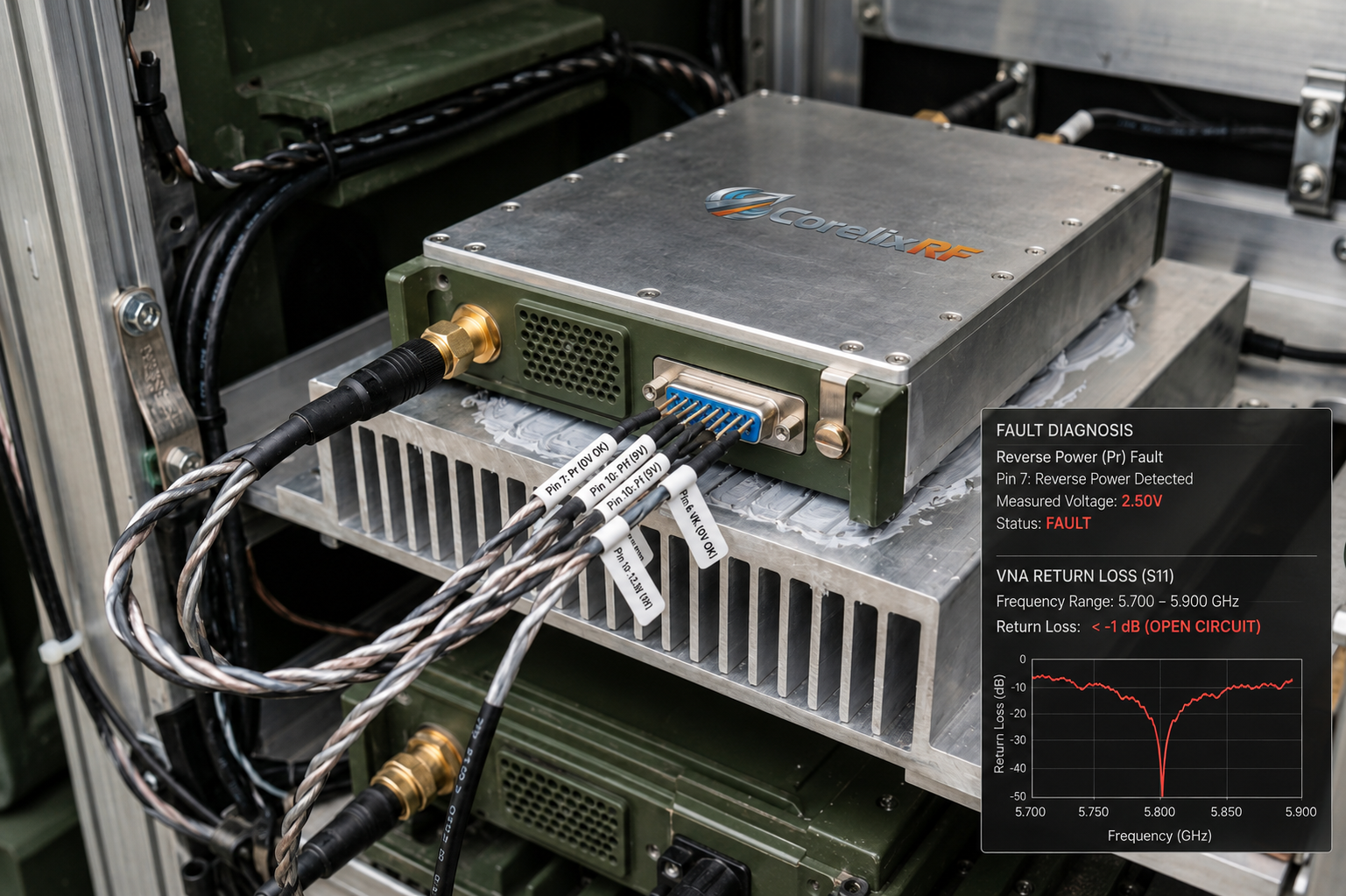
Field Troubleshooting: Infantry Radio Antenna Failures. Combat deployments subject communication gear against severe mechanical trauma. Connectors snap during rapid maneuvers. Snapped elements reflect massive energy backwards into transmitters. Our analysis details practical diagnostic steps. We explore hardware countermeasures against terminal equipment burnout.
1. How Do Tactical Operations Induce Antenna Damage?
● Physical impact scenarios
● Connector fatigue mechanisms
● Cable stress points
Infantry radios operate amidst constant physical abuse. Soldiers navigate dense foliage carrying heavy equipment. Branches frequently snag protruding whip antennas. Such violent impacts fracture internal radiating elements instantly. Here’s the deal: fractured metal disrupts characteristic impedance completely. RF signals encounter massive discontinuities at broken junctions. A snapped SMA-KFD46 joint creates an immediate open circuit. Continuous movement loosens threaded connections over several hours. Vibration gradually degrades contact pressure between mating surfaces. Field personnel rarely notice loose fittings until transmissions drop. Rainwater breaches compromised seals, altering dielectric properties immediately. Water ingress shifts resonant frequencies far outside operational bands. These environmental factors combine, guaranteeing severe mismatch conditions. Regular combat patrols practically ensure some degree of structural failure. Frontline maintainers observe snapped connectors almost daily. We see identical failure patterns across multiple deployment theaters. Mechanical robustness dictates survival probability for portable transmitters. Tactical communication depends heavily upon intact radiating structures. Consider vehicular dismounts striking door frames constantly. Man-portable kits slam against brick walls during urban breaching operations. Shrapnel routinely severs coaxial feedlines during heavy firefights. These three examples illustrate unavoidable battlefield attrition perfectly. Engineers cannot prevent physical damage realistically. Our focus shifts toward managing catastrophic electrical consequences exclusively.
Antenna Failure Modes
| Failure Type | Root Cause | Immediate Electrical Effect |
| Element Fracture | Tree snagging | Complete open circuit |
| Loose Connector | Vibration | Intermittent high VSWR |
| Water Ingress | Seal degradation | Shifted resonant frequency |
2. Why Does Reflected Energy Cause System Degradation?
● Impedance mismatch fundamentals
● Standing wave formation
● Power delivery failure
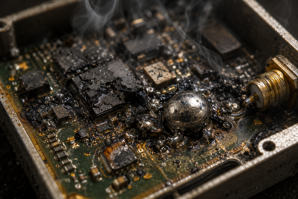
Transmitters generate 100 W output power continuously. They expect exactly 50 ohms termination for optimal transfer. Broken antennas present infinite impedance back towards output stages. You might be wondering: where does that generated power go? Energy cannot disappear from isolated circuits. RF waves hit broken boundaries and bounce back immediately. Forward and reverse signals combine into massive standing waves. Voltage peaks along coaxial lines exceed breakdown thresholds rapidly. High voltages puncture transistor gate oxides without warning. Reflected current generates extreme localized heating inside semiconductor dies. Heat degrades electron mobility, dropping overall amplification efficiency drastically. A 5700 – 5900 MHz signal packs immense energy concentration. Trapped 100 W energy destroys sensitive components within microseconds. Complete energy transfer requires perfectly matched load conditions constantly. Any deviation sends destructive reflections directly into delicate amplifiers. Output power plummets when mismatches trigger internal protection loops. Sustained reflections guarantee total hardware failure unless mitigated quickly. Reflected energy literally cooks internal PCB traces rapidly. Imagine firing a water hose directly against a solid brick wall. Water splashes back aggressively, soaking everything nearby. Microwave energy behaves identically inside coaxial structures. A mismatched signal creates intense localized heating. Field teams replacing burnt amplifiers notice melted solder joints frequently. Component failure analysis reveals blackened transistor substrates consistently. System integrators lose thousands of dollars per burnt module. Protecting high-frequency systems demands uncompromising electrical rigor.
3. What Physical Mechanisms Drive Thermal Runaway?
● Die junction heating
● Efficiency collapse
● Uncontrolled current draw
Amplifiers operating at high frequencies dissipate significant waste heat. CorelixRF specifies 24-32 V supply ranges for optimal operation. Normal transmission converts DC power into RF efficiently. High VSWR conditions destroy this carefully tuned conversion process. Mismatched loads force output transistors out of optimal regions. What’s the catch? Devices draw maximum current while delivering zero forward power. A module pulling 20 A dissipates hundreds of watts internally. Heat accumulates faster than external heat sinks can manage. Rising die temperatures increase leakage currents exponentially. Higher leakage triggers even greater current draw from supplies. This vicious cycle defines catastrophic thermal runaway perfectly. Operating temperatures exceeding +60°C accelerate degradation mechanisms rapidly. Silicon structures melt down when junction temperatures surpass absolute maximums. Engineers find scorched boards near final stage amplifier sections. Thermal runaway acts silently until visible smoke appears. Proper thermal management requires immediate RF shutdown during mismatch events. Passive heat sinks alone cannot stop active runaway chains. We analyzed failed units from desert deployments recently. Ambient temperatures exceeding +50°C left zero thermal margin originally. Transistors operating heavily generated unmanageable heat loads immediately. The heat sinks saturated within ten minutes completely. Internal die temperatures spiked past critical limits violently. Thermal cameras captured glowing hotspots near output matching networks. These case studies prove passive cooling fails under fault conditions. Active protective circuitry remains absolutely necessary for equipment survival. Engineers must design fail-safe mechanisms anticipating extreme thermal stress.
Thermal Runaway Stages
| Stage | Current Draw | Die Temperature | Consequence |
| Mismatch | Normal | Rising slowly | Efficiency drop |
| Leakage | Increasing | Spiking | Hot spots form |
| Runaway | >20A | Critical | Catastrophic failure |
4. How Can Field Engineers Diagnose Impedance Mismatches?
● Initial visual inspections
● Pin voltage monitoring
● System log analysis
Frontline diagnostics require pragmatic approaches under pressure. Combat environments limit access toward sophisticated laboratory equipment. Engineers must rely upon integrated hardware telemetry directly. CorelixRF modules provide Pin 10 Pf and Pin 7 Pr indicators. Let me explain: these analog voltages represent forward and reverse power. Technicians probe these pins using basic digital multimeters. A high Pr voltage immediately flags severe antenna faults. Normal operation shows near-zero volts on reverse power pins. Pin 13 VA triggers a 5V alarm during open circuits. Multimeter readings exceeding normal thresholds demand immediate transmission cessation. We inspect physical cable routes for obvious crushing damage. Disconnected SMA-KFD46 ports clearly explain infinite VSWR readings. Smart telemetry isolates external faults from internal amplifier failures quickly. Quick diagnosis saves expensive hardware from sustained abuse. Maintaining operational readiness depends entirely upon rapid fault isolation. Engineers trust deterministic analog voltage readings above complex software errors. Field mechanics face intense pressure restoring communications quickly. A commander screaming for radio support demands instant results. Technicians grabbed digital multimeters for immediate troubleshooting protocols. Checking Pin 10 Pf revealed zero forward transmission power. Moving probes towards Pin 7 Pr displayed alarming 2.5V readings. This specific diagnostic sequence saved hours of blind guessing. Another unit identified faulty cables via Pin 13 VA 5V flags. Analog pins offer foolproof telemetry bypassing complex software menus. Military maintainers appreciate this raw hardware transparency greatly.
5. Which Measurement Tools Verify VSWR Anomalies?
● Directional couplers
● Portable network analyzers
● Analog multimeters
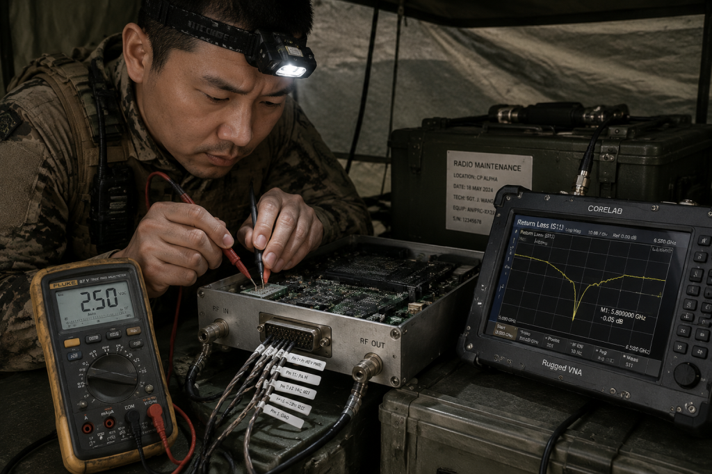
Advanced verification requires specialized RF measurement tools. Portable Vector Network Analyzers identify precise fault locations accurately. VNAs inject sweep frequencies across 5700 – 5900 MHz bands. This is where things get interesting: Time Domain Reflectometry pinpoints exact cable break distances. TDR modes send short pulses down coaxial lines. The instrument measures return times for reflected pulses. A break 2 meters away shows a distinct reflection peak. Standard directional couplers verify high power forward/reverse ratios directly. We insert couplers between amplifier outputs and antenna feeds. Attenuated ports connect toward ruggedized portable spectrum analyzers. This setup measures harmonic content reaching -10 dBc limits potentially. Field technicians carry ruggedized multimeters for basic D-Sub 15-Pin checks. Checking Pin 12 TA confirms whether over-temperature shutdowns occurred. Combining VNA data with analog pin telemetry builds complete pictures. Accurate tool usage prevents replacing functional power amplifiers unnecessarily. Tool proficiency defines a master field troubleshooting technician. A Marine unit utilized portable VNAs during recent exercises. They swept suspect antennas across wide frequency bands. The display showed massive return loss spikes near 5800 MHz. Another team used directional couplers for measuring actual power flow. They recorded 40W reverse power reflecting off damaged whips. This empirical data justified complete antenna replacement immediately. A third squad monitored Pin 12 TA during high-duty-cycle transmissions. They verified adequate cooling performance via 10mV/°C analog outputs. Mastering these instruments separates amateur mechanics from seasoned professionals.
Diagnostic Pin Guide
| Pin Number | Function | Normal State | Fault State |
| Pin 10 | Forward Power (Pf) | 0-3V varying | 0V |
| Pin 7 | Reverse Power (Pr) | ~0V | >1V |
| Pin 13 | Output Alarm (VA) | 0V | 5V |
6. Why Do Commercial Amplifiers Fail Under Combat Stress?
● Lack of ruggedization
● Insufficient protection circuits
● Poor thermal handling
Commercial-off-the-shelf amplifiers prioritize cost over extreme survivability. They omit robust reverse power protection circuitry deliberately. Consumer gear assumes users connect antennas properly before transmitting. Tactical realities destroy such optimistic engineering assumptions completely. Truth be told: infantry grunts break delicate equipment constantly. A standard commercial PA fries itself within milliseconds under open-load. They lack fast-acting ALC loops for VSWR fold-back protection. Standard FR4 PCB materials degrade quickly under high temperatures. Their commercial connectors withstand perhaps fifty mating cycles maximum. We see field-returned COTS units suffering melted solder joints regularly. They cannot handle 100 W continuous saturation power during faults. Commercial software control loops react too slowly against hard shorts. Microcontroller-based protection introduces fatal latency during sudden antenna snaps. RF energy outpaces digital polling loops every single time. Military applications demand purely analog, zero-latency protection mechanisms. Cutting costs on protection circuits guarantees total system failure. We tested several commercial amplifiers against simulated battle conditions. Unit Alpha melted its power supply during a dead-short test. Unit Bravo suffered permanent gain degradation following mild VSWR mismatches. Unit Charlie’s software crashed while processing overvoltage telemetry data. These three catastrophic failures demonstrate commercial vulnerability clearly. COTS designs lack ruggedized SMA-KFD46 interface durability completely. Their plastic housings offer zero EMI shielding during jamming scenarios. Infantry radios require military-grade components strictly. Budget-focused procurement decisions cost lives during actual combat deployments.
7. What Makes CRF-PA-5700M5900M-100W Robust Against Open Circuits?
● Internal circulator integration
● Fast analog protection
● Ruggedized SMA connectors
CorelixRF designed the CRF-PA-5700M5900M-100W specifically for harsh realities. This module survives accidental open or shorted outputs. We integrated sophisticated analog detection directly on RF boards. The bottom line is: analog comparators trigger shutdown sequences within nanoseconds. Pin 13 VA monitors output standing waves continuously. It triggers a 5V alarm instantly upon detecting severe mismatch. High-power circulators absorb initial reflected energy spikes effectively. This physical barrier prevents energy returning into final transistors. The SMA-KFD46 connector withstands severe mechanical vibration profiles. We built the enclosure using thick 160 × 120 × 25 mm aluminum. This massive block dissipates sudden thermal transients rapidly. The 1.4 kg weight provides immense thermal inertia during emergencies. The PA Enable/Disable Time clocks below 100 μs strictly. Fast disabling cuts power before thermal runaway initiates. This ruggedized design guarantees survival across demanding combat deployments. Our lab subjected the CRF-PA-5700M5900M-100W against brutal validation protocols. We slammed output ports with infinite VSWR shorts intentionally. The internal analog comparators reacted flawlessly every single time. Another test injected severe vibration profiles matching tracked vehicles. The heavy chassis remained structurally intact. A third trial pushed operating temperatures past +60°C continuously. Pin 12 TA triggered safety shutdowns perfectly on schedule. These extreme trials validate our core engineering methodology definitively. Real-world ruggedness requires uncompromising hardware design choices fundamentally.
CorelixRF Protection Features
| Feature | Mechanism | Benefit |
| Pin 13 VA | Analog comparator | Instant VSWR alarm |
| Pin 12 TA | Thermal sensor | Over-temperature shutdown |
| 100 μs Disable | Hardware switch | Prevents transistor damage |
8. How Does Active Hardware Protection Prevent Device Burnout?
● Current limiting circuits
● Voltage clamp mechanisms
● Hardware alarm interrupts
Hardware-level protection always outperforms software-based monitoring systems. Our engineering team hardwired critical limiters directly into bias networks. Pin 3 Current Alarm activates whenever supply draw exceeds 22A. It boils down to this: hardware cuts bias voltages automatically. Removing gate bias stops amplification instantly, dropping current zero. Pin 2 Voltage Alarm acts similarly for input spikes exceeding 32V. Overvoltage conditions destroy sensitive RF laterally diffused metal-oxide semiconductors. The protection circuit shunts dangerous transients away from sensitive dies. Pin 6 Alarm Reset requires deliberate external pulses for recovery. This prevents dangerous oscillating on-off cycles during intermittent faults. A flapping antenna connection won’t destroy our protection relays. Hardware logic demands absolute stability before allowing transmission resumption. Pin 11 PA_EN requires intentional 0V signals for activation. Floating pins disable outputs securely by default. Hardwired safety protocols ensure maximum equipment lifespan during combat. Active protection means troops return home with functional radios. Consider a vehicle crushing its primary transmission antenna accidentally. The module detects massive impedance shifts instantaneously. Pin 3 Current Alarm fires before transistors draw fatal currents. A separate incident involved lightning-induced voltage surges nearby. Pin 2 Voltage Alarm clamped the 32V input spike safely. Another scenario featured intermittent loose cables causing chaotic reflections. Pin 6 Alarm Reset held transmissions offline until manually cleared. These protective layers act independently from main system processors. Hardware autonomy guarantees survival when software routines freeze.
9. What Are Core Integration Requirements For Vehicle Systems?
● Power supply conditioning
● RS485 bus configuration
● Physical mounting strategies
Vehicle-mounted infantry systems introduce unique electrical integration challenges. Vehicle alternators generate massive voltage spikes during engine starts. CorelixRF amplifiers require stable 28V nominal DC power. Integrators must install heavy-duty transient voltage suppressors upstream. Here’s what you need to know: clean power prevents false alarm triggers. System controllers communicate via Pin 1 and Pin 8 RS485 lines. This master-slave bus monitors voltage, current, and output power. RS485 cables require proper twisted-pair shielding against vehicle EMI. High-vibration environments demand locking D-Sub 15-Pin control connectors strictly. Integrators must torque mounting bolts securely into flat chassis plates. The 160 × 120 × 25 mm footprint fits standard tactical racks easily. Proper grounding through dedicated posts prevents dangerous chassis ground loops. Bad grounding injects alternating current noise into transmit signals. System integrators must validate continuous ground paths before deployment. Flawless vehicle integration ensures reliable 100W output continuously. A Stryker brigade integrated these modules into tactical networks successfully. They routed Pin 1 and Pin 8 RS485 lines directly. The master controller adjusted gain settings via 0.5dB steps remotely. Another project utilized Pin 5 attenuator settings for variable power. They supplied 0.5–3.0 VDC for precise output scaling. A third application required remote silent-running capabilities strictly. They applied 5V on Pin 11 PA_EN, killing emissions instantly. Complete system mastery requires exploiting every single D-Sub pin efficiently.
Integration Interface Specifications
| Pin Element | Function | Critical Vehicle Requirement |
| Pin 1 / 8 | RS485 Data | Twisted-pair shielded cable |
| Pin 11 | PA Enable | Hardwired toggle switch |
| GND Post | Grounding | Direct chassis connection |
10. How Can Technicians Implement Proper Cooling Strategies?
● External heat sink sizing
● Thermal interface materials
● Airflow management

Operating a 100W linear amplifier demands aggressive thermal management. The CRF-PA-5700M5900M-100W requires external heat sinks necessarily. Bare modules overheat quickly operating at 20A current levels. Let’s face it: physics dictates heat must go somewhere. Technicians must spread high-quality thermal grease across baseplates evenly. Voids in thermal interfaces create dangerous localized hot spots. We monitor baseplate heat via Pin 14 Tc analog voltages. This pin outputs 10mV per degree Celsius accurately. System controllers read this voltage, accelerating external cooling fans accordingly. Forced air must flow parallel along finned sink structures. Stagnant air trapped inside vehicle compartments causes rapid overheating. Pin 12 TA triggers 5V alarms during severe over-temperature events. Proper sink sizing keeps normal operations below +60°C comfortably. Combat environments demand robust environmental testing heavily. Thermal engineering defines long-term reliability for high-power microwave systems. An airborne test platform required specialized aluminum heat sinks urgently. Engineers milled custom cooling fins matching chassis dimensions perfectly. They achieved continuous 100W output despite thin atmospheric conditions. Another ground station utilized forced liquid cooling plates successfully. They monitored Pin 14 Tc voltages, adjusting pump speeds dynamically. A desert outpost built sun-shields protecting exposed amplifier surfaces. These three thermal strategies prevented dangerous +85°C storage extremes. Managing thermodynamics dictates operational tempo for high-power microwave gear. Clever engineering defeats hostile ambient environments consistently.
Infantry radio survivability hinges upon managing reflected RF energy effectively. Antenna damage triggers catastrophic mismatches requiring instantaneous hardware-level protection. CorelixRF designed the CRF-PA-5700M5900M-100W specifically for conquering brutal tactical environments. System integrators must leverage our integrated diagnostic telemetry for ultimate reliability. Frontline teams depend upon unbreakable microwave hardware daily. Contact our engineering team for customized military solutions today.
FAQ Section
- Q1: What is an RF impedance mismatch?
- An impedance mismatch occurs when antenna properties deviate from ideal 50-ohm conditions, causing energy reflections.
- Q2: How does the CRF-PA-5700M5900M-100W protection work?
- It utilizes analog comparators monitoring Pin 7 Pr reverse power, shutting down outputs instantly upon detecting severe standing waves.
- Q3: Why do infantry antennas fail frequently?
- Combat environments subject communication gear against severe physical impacts, breaking connectors and severing radiating elements unexpectedly.
- Q4: Which pins provide direct power telemetry?
- Pin 10 outputs forward power voltage, while Pin 7 provides reverse power readings for quick field diagnostics.
- Q5: How should engineers manage module cooling?
- Integrators must mount PA modules onto appropriately sized external heat sinks utilizing high-quality thermal interface materials.
Authorized RF engineering and compliance review
For regulated RF systems, this page should be used as an engineering and compliance review path, not as a public deployment checklist. CorelixRF starts with authorization status, operating region, frequency plan, output limit, antenna interface, safety controls, thermal limits and acceptance documents.
- RFQ checklist – send the data buyers usually forget, including band, power, duty cycle, interface and test standard
- delivery documentation – check what documents can support incoming inspection, FAT review and long-term maintenance
- quality and certification review – review the quality and compliance evidence before the project moves into procurement
- RF front-end platform – compare the RF chain as a system instead of selecting one isolated module
- RF configurator – turn frequency, power, thermal and interface requirements into a first configuration brief
- case studies – review similar engineering paths before sending an RFQ
- engineering contact – send the application notes, block diagram or target specification to engineering sales
This keeps the discussion inside lawful, authorized RF programs while still giving procurement teams a clear way to request amplifier, antenna, SDR source, documentation and factory review.