
1. Why do accidental antenna damages cause catastrophic failures in infantry radio design?
● Broken whips
● Open circuits
● Voltage peaks
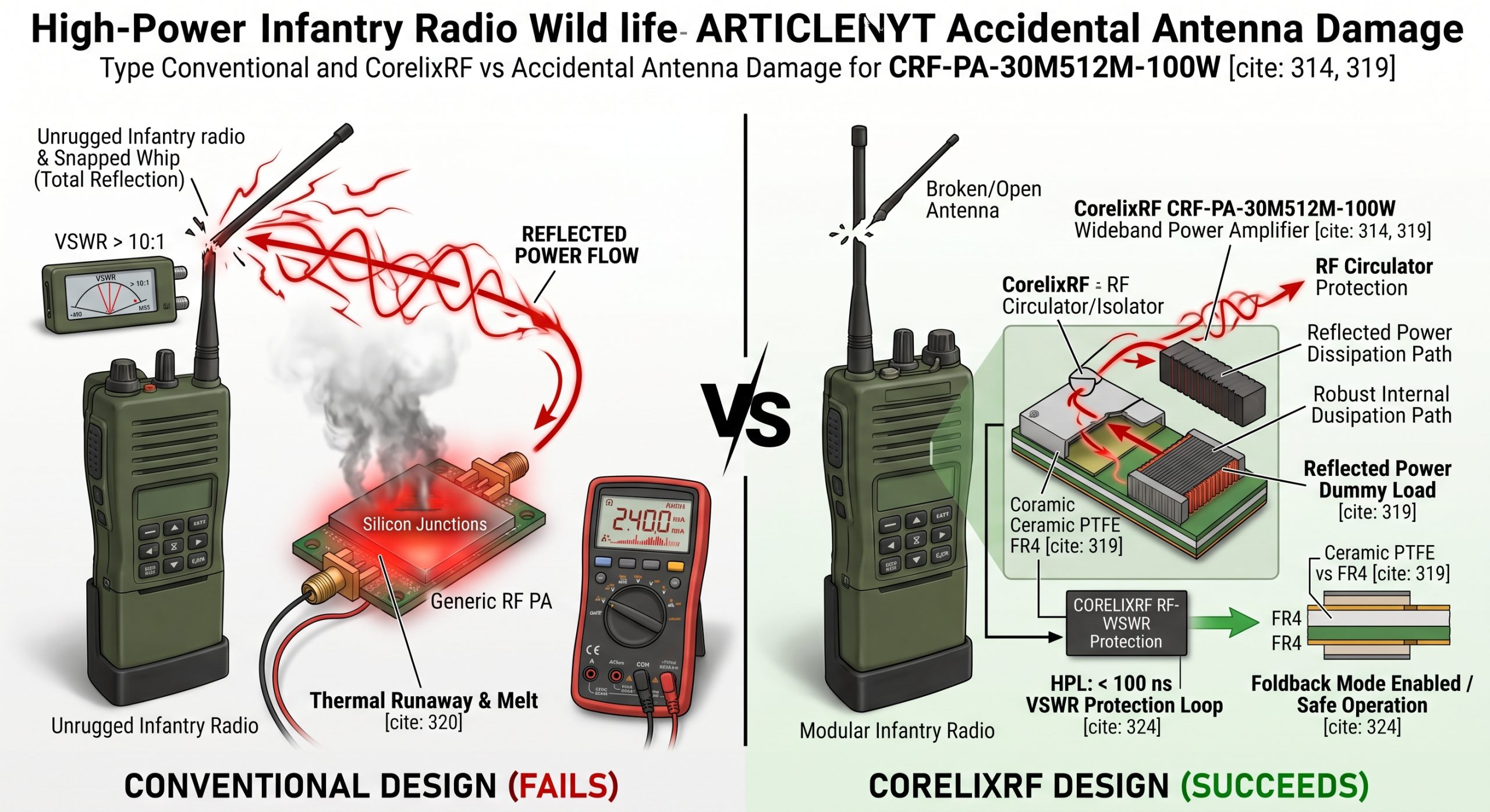
When soldiers crawl through dense foliage, whip antennas snap. This sudden break creates an open circuit. Here is the deal: radio transmission continues regardless of structural integrity. Energy heading outward hits that boundary point and violently reflects backwards. We see total reflection generating massive standing waves inside coaxial cables. This massive voltage peak stresses internal components beyond their rated limits. Infantry radio design requires accounting for these unpredictable physical impacts. Without proper ruggedization, final stage transistors face instantaneous overvoltage conditions. You might be wondering: how fast does destruction occur? Microseconds are all it takes for silicon junctions melting down. Your system experiences sudden silence right during critical mission phases. A snapped element means 100 watts of power have nowhere safe. We must build architectures capable of surviving extreme impedance mismatches. Field engineers constantly observe melted matching networks after such events. High-frequency energy bouncing back creates nodes possessing double normal voltages. Standard commercial gear immediately perishes under such hostile electrical conditions. You cannot expect pristine lab environments during heavy mechanized deployments. Every design choice must prioritize survival above maximum theoretical efficiency. Only robust physics-based engineering guarantees continuous communication when equipment breaks.
Common Infantry Radio Antenna Faults
| Fault Type | Physical Cause | RF Consequence |
| Snapped Whip | Foliage impact | Infinite impedance |
| Cut Coax | Shrapnel damage | Total reflection |
| Loose Connector | High vibration | Erratic mismatch |
2. How does reflected energy reverse flow initiate thermal runaway?
● Wave superposition
● Heat accumulation
● Cooling limits
Reflected power traveling back hits your final amplifier stage. What is the real story? That returning signal combines constructively with forward waves. This superposition creates massive localized voltage nodes. Components turn that trapped microwave energy into pure heat. Junction temperatures inside active devices spike rapidly. A standard cooling mechanism cannot dissipate such concentrated thermal bursts. Infantry radio design must address this rapid heat accumulation. As silicon heats up, its current draw increases uncontrollably. This cycle accelerates until physical breakdown happens. The CRF-PA-30M512M-100W uses air cooling for managing its 100 W output. However, excessive returning power overwhelms standard dissipation limits. You need specific architectural safeguards against this runaway loop. Otherwise, field units literally burn from inside out. But here is the kicker: typical lab tests rarely simulate actual combat-level mismatch duration. Lab technicians usually apply mismatches for only brief testing intervals. Real scenarios involve broken antennas transmitting continuously across long patrols. Heat sinks saturate quickly under continuous mismatched wave conditions. Baseplate temperatures soar past operating thresholds almost immediately. We engineer thermal paths accounting for sustained high-VSWR states.
3. What are common BOM selection traps for matching networks?
● Commercial capacitors
● Ferrite limitations
● Component detuning
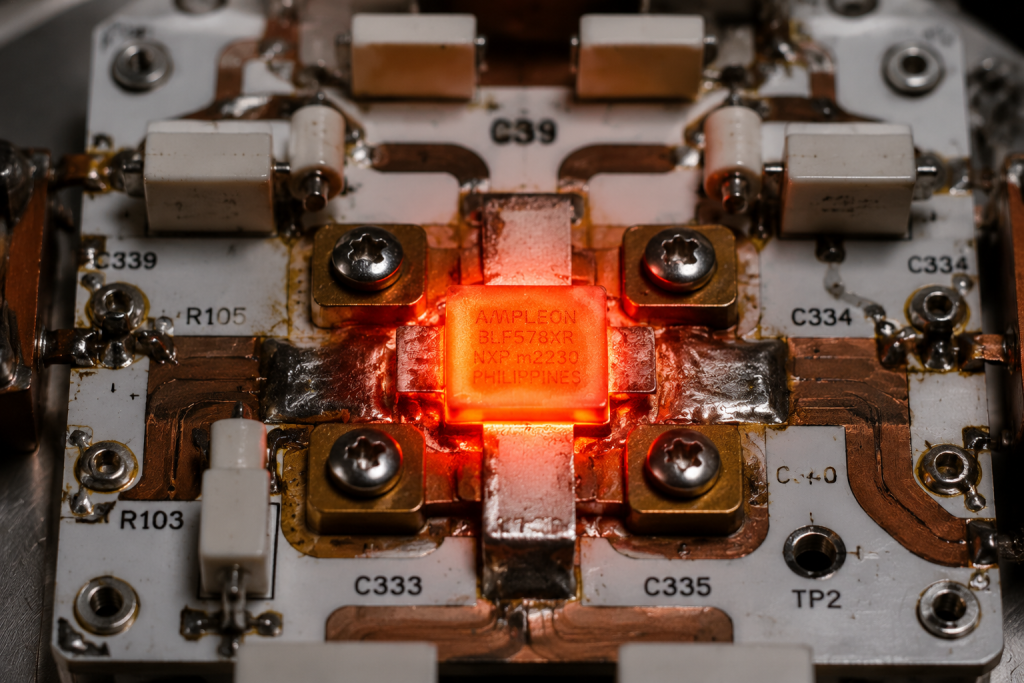
Engineers often select commercial-grade capacitors for front-end matching. This is where it gets interesting… Those components specify adequate power handling at 50 ohms. An open antenna shifts that impedance wildly. Voltage across those cheap capacitors quadruples instantly. Dielectric breakdown follows shortly after. Another trap involves using ferrite beads with low Curie temperatures. High standing waves cause those ferrites overheating rapidly. They lose their magnetic properties entirely. Your matching network completely detunes itself. A detuned network worsens that original mismatch exponentially. Infantry radio design demands components rated for worst-case voltage standing wave ratios. Think about it: saving pennies on capacitors costs thousands in replaced field units. We mandate utilizing high-voltage porcelain capacitors for military applications. These specific choices prevent cascade failures during unpredictable field deployments. High-Q air core inductors replace easily saturated magnetic cores. Brass SMA connectors degrade rapidly under harsh mechanical vibrations. Stainless steel bodies provide superior torque resistance under field stress. Every component must survive both electrical spikes and physical abuse.
BOM Selection Matrix for Matching Networks
| Component Type | Commercial Grade | Military Grade |
| Capacitors | Standard MLCC | High-Voltage Porcelain |
| Inductors | Ferrite Core | Air Core |
| Connectors | Brass SMA | Stainless Steel |
4. Why do generic low-cost amplifiers fail under high VSWR conditions?
● Delicate LDMOS
● Slow protection
● Hardware beats software
Generic modules prioritize high efficiency over ruggedness. Ready for the good part? They use delicate LDMOS dies optimized strictly for perfect 50-ohm loads. When field conditions degrade, these dies lack sufficient breakdown voltage margins. An open circuit creates reflections exceeding their structural tolerances. The device simply shorts out. Furthermore, cheap designs lack robust protection circuitry. They rely on slow firmware algorithms sensing trouble. RF energy moves much faster than software polling rates. Microseconds pass before any protective attenuation kicks in. By then, that transistor junction has already vaporized. Infantry radio design necessitates hardware-level protection mechanisms. The CRF-PA-30M512M-100W operates safely across 30-512 MHz. Its architecture inherently withstands poor loads without relying on sluggish software. Make no mistake: hardware ruggedness always beats software mitigation. A rugged architecture survives dead shorts indefinitely without degrading performance. We utilize older but tougher silicon structures favoring high survivability. Modern telecom chips cannot handle infantry-level physical punishment reliably.
5. How can we calculate budget margins for a 30-512 MHz system?
● Real-world losses
● Saturated power
● Conservative planning
Calculating budget margins requires understanding real-world losses. Listen closely: textbook equations assume pristine cables. Combat environments involve dirty connectors. We must factor in elevated insertion loss from physical degradation. The CRF-PA-30M512M-100W delivers 100 W saturated output power. We allocate at least 3 dB for unpredicted mismatch losses. Another 2 dB accounts for thermal derating under direct sunlight. This conservative approach guarantees reliable transmission. Infantry radio design cannot rely on best-case scenarios. A rugged system maintains connectivity despite severely degraded antenna efficiency. We calculate margins assuming worst possible standing wave ratios. Truth be told: planning for failure guarantees mission success. Your link budget must accommodate sudden impedance shifts without dropping communication entirely. Desert deployments experience massive temperature swings ruining cable impedance matching. You must oversize your final amplifier stages compensating for these losses. Bare minimum specifications inevitably lead toward dropped tactical links. Over-engineering your RF budget saves lives during chaotic engagements.
Link Budget Allocation Factors
| Parameter | Value | Justification |
| Output Power | 100 W | Saturated requirement |
| Mismatch Loss | 3 dB | Accounts for dirty connectors |
| Thermal Derating | 2 dB | Direct sunlight compensation |
6. What role does the CRF-PA-30M512M-100W play in resolving VSWR faults?
● Resilient stage
● Isolation benefits
● Controlled current
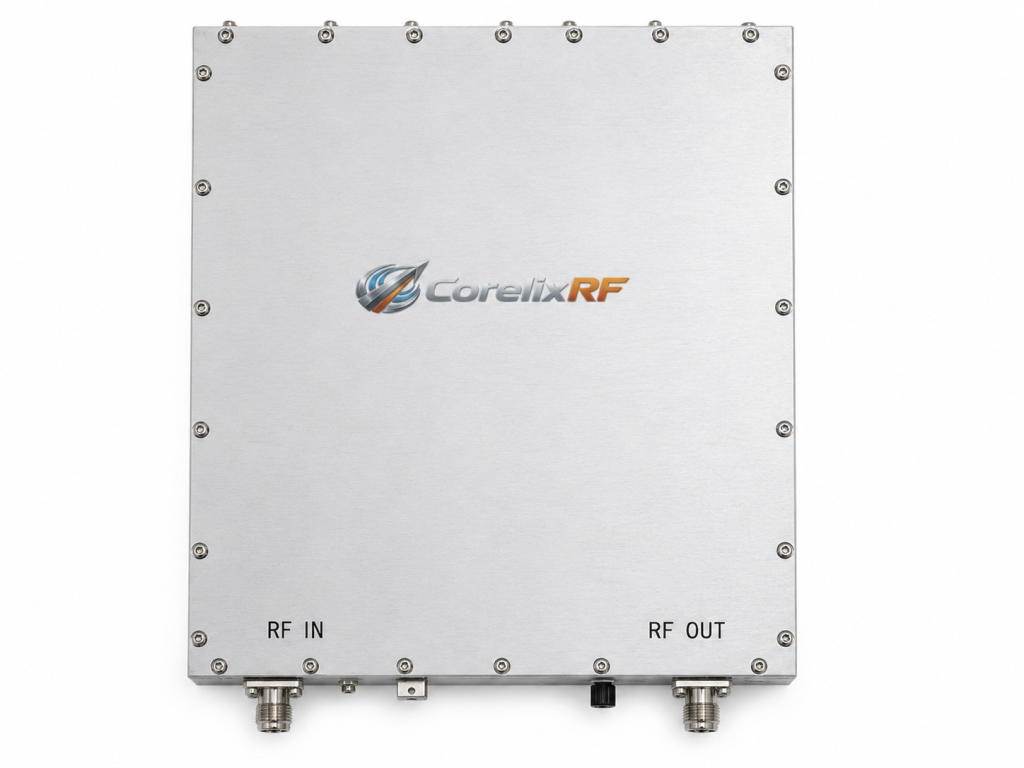
This specific module features an inherently resilient output stage. Here is the secret: it utilizes specialized semiconductor processes. These dies boast massive breakdown voltage ratings. Even under total reflection, voltage peaks remain below critical thresholds. The CRF-PA-30M512M-100W limits output VSWR $\le2.0$:1. This prevents returning energy cascading backwards into driver stages. Infantry radio design benefits massively from this isolation. Supply voltage requires 28 VDC. Current consumption remains $\le18$ A. A controlled current limit prevents thermal runaway naturally. You do not need complex external sensing loops. The amplifier absorbs that reflected punishment directly. It gets better: this integrated toughness reduces total system complexity significantly. We provide stability across broad frequency ranges. Engineers can deploy this unit across multiple vehicle platforms easily. Consistent gain across wide bands simplifies matching network designs tremendously. Our architecture removes delicate failure points from your signal chain.
7. How does hardware circuit design prevent reverse power dissipation?
● Fast comparators
● Bias cutoff
● Rugged circulators
Effective architectures employ directional couplers combined with fast analog comparators. Pay attention here: software cannot react fast enough. We route reflected signals directly into an analog shutdown loop. This loop pinches off bias voltage within nanoseconds. The amplifier safely powers down before junction temperatures rise. Another method involves employing rugged circulators where bandwidth allows. A circulator shunts returning energy into a dedicated dummy load. This completely isolates our fragile active devices. The CRF-PA-30M512M-100W operates reliably from -40 °C up through +85 °C. It manages heat efficiently through robust mechanical coupling. Infantry radio design relies heavily upon these instantaneous hardware protections. You see: physics cannot be outsmarted by mere code. Solid electrical engineering remains your best defense against extreme mismatch events. Hardware limits kick in before smoke ever leaves your chassis. An analog loop resets itself instantly once fault conditions clear. This automatic recovery keeps operators focused on combat entirely.
Hardware Protection Mechanisms
| Technique | Response Time | Component Handled |
| Analog Bias Cut | Nanoseconds | Voltage Spikes |
| RF Circulator | Continuous | Reflected Power |
| Thermal Pad | Minutes | Baseplate Heat |
8. What high-frequency materials survive combat-level thermal stress?
● Ceramic PTFE
● Thermal mass
● Specialized alloys
Standard FR4 PCB materials carbonize under high microwave power. Here is a harsh reality: carbonized boards become conductive. That ruins any isolation between RF traces. We utilize specialized ceramic-filled PTFE substrates. These materials maintain stable dielectric constants during extreme heating. Furthermore, they conduct heat laterally away from active components. The CRF-PA-30M512M-100W utilizes a $200\times158\times25~mm$ chassis for maximum thermal mass. We attach those PTFE boards using highly conductive silver epoxy. This eliminates air voids causing localized hotspots. Infantry radio design requires packaging surviving both vibration and heat. Generic solder cracks under constant mechanized transport stress. We employ specialized alloys resisting both thermal cycling fatigue and high-frequency shaking. This matters because: mechanical failure inevitably leads directly toward electrical failure. A cracked solder joint creates microscopic arcing destroying adjacent traces. Heavy copper plating helps spread thermal loads across wider surface areas. This material synergy creates virtually indestructible RF front ends.
9. How do we diagnose RF front-end issues using field instruments?
● VNA testing
● Wattmeter confirmation
● Robust test ports
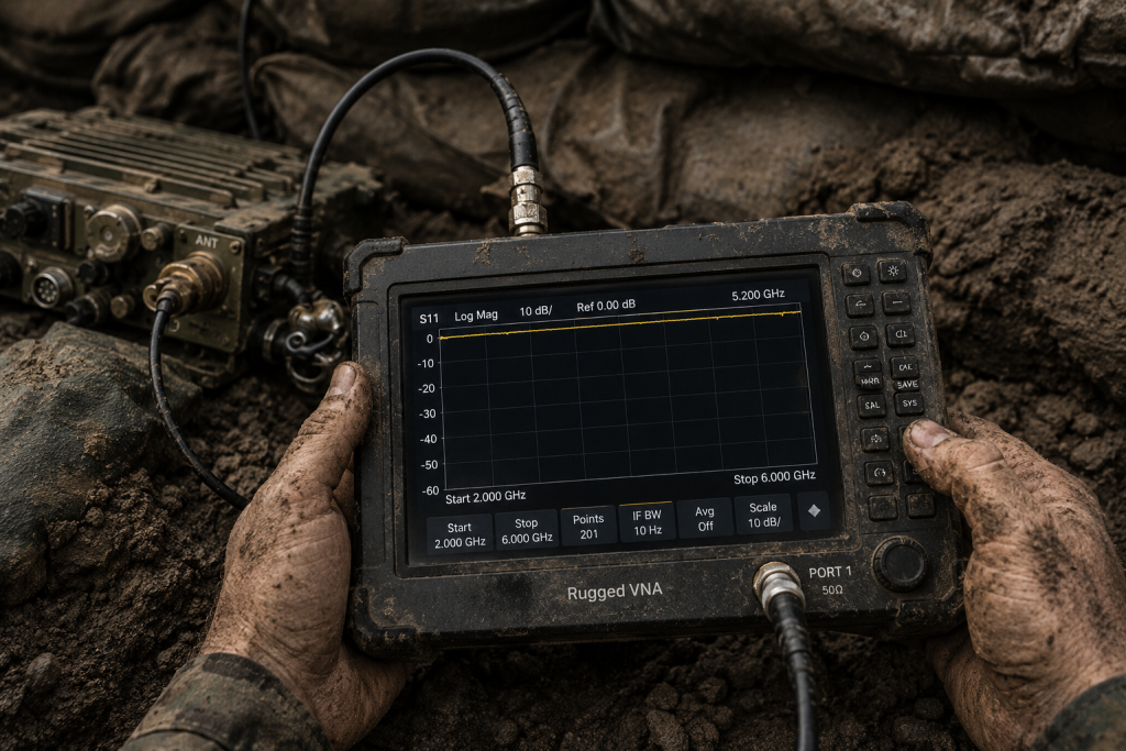
Field technicians face unique challenges diagnosing broken radios. Let me explain: you cannot bring full lab setups into a trench. We rely on ruggedized portable Network Analyzers. When testing, a collapsed S11 curve at high frequencies indicates severe trouble. A normal system shows a clean match. An open antenna creates a flat zero-return line. You hook up your directional wattmeter next. Forward power reads normal but reflected power pegs that needle hard. This confirms your antenna network has failed completely. Infantry radio design must include accessible test ports. The CRF-PA-30M512M-100W uses an SMA-Female input and N-Female output. These robust connectors survive repeated mating cycles during field diagnostics. Keep in mind: accurate diagnosis saves hours of pointless component swapping under fire. Broken cables often mimic amplifier failures during initial hasty inspections. Proper training with portable spectrum analyzers reveals hidden noise floor issues quickly. You must isolate each block before swapping expensive modules blindly.
Field Diagnostic Signatures
| Instrument | Reading | Fault Indication |
| VNA (S11) | Flat trace near 0 dB | Open or shorted antenna |
| Wattmeter | High reflected power | Poor impedance match |
| Spectrum Analyzer | Elevated noise floor | Active device degradation |
10. What engineering practices guarantee long-term reliability in harsh environments?
● Thermal shock
● Conformal coating
● Physical realities
Long-term survival demands brutal validation testing during development. The truth is: simulations lie constantly. We subject every prototype through aggressive thermal shock cycles. We purposely snap antennas while transmitting full power. If smoke appears, that design goes straight into a trash bin. The CRF-PA-30M512M-100W weighs $\le1.4$ kg. This weight balances ruggedness with portability perfectly. We conformal coat every board combatting salt fog. This prevents dendritic growth across high voltage traces. Infantry radio design means planning for operators abusing equipment daily. Cables will constantly be yanked during field deployments. Connectors will get packed with mud. Assuming worst-case conditions helps us engineer systems refusing catastrophic failure. Ultimately: true reliability comes from embracing physical realities rather than ignoring them. Your radio must fight just as hard as your soldiers do. We log thousands of hours blasting modules with severe vibrations. Only empirical testing validates these mission-critical RF architectures properly.
Proper infantry radio design demands respecting raw physical forces. The CRF-PA-30M512M-100W provides a heavily fortified foundation against catastrophic antenna failures. Field survivability relies entirely on strict hardware protection and superior materials. Contact our engineering team today for immediate integration support regarding your next critical project.
- Q1: What is infantry radio design?Infantry radio design involves engineering highly rugged communication systems specifically built for combat scenarios. These systems must survive extreme physical abuse while maintaining reliable RF transmission.
- Q2: How does reflected energy reverse flow work?When an antenna breaks, it creates an open circuit mismatch. Forward transmitting power hits this break and bounces backwards into your amplifier. This creates massive voltage standing waves leading directly toward thermal runaway.
- Q3: Why are specific BOM choices necessary?Commercial parts fail under high voltage standing waves. We must select military-grade capacitors and specialized substrates. These robust components survive massive voltage spikes without suffering catastrophic dielectric breakdown.
- Q4: How do we diagnose field failures accurately?Engineers use portable vector network analyzers analyzing S11 curves. A collapsed curve indicates a severe mismatch. Directional wattmeters confirm this by showing extremely high reflected power levels.
- Q5: What makes the CRF-PA-30M512M-100W ideal for this application? This module delivers a robust 100 W output across a wide 30-512 MHz band. Its rugged internal architecture handles high VSWR conditions safely without relying on slow software protection.
Authorized RF engineering and compliance review
For regulated RF systems, this page should be used as an engineering and compliance review path, not as a public deployment checklist. CorelixRF starts with authorization status, operating region, frequency plan, output limit, antenna interface, safety controls, thermal limits and acceptance documents.
- RFQ checklist – send the data buyers usually forget, including band, power, duty cycle, interface and test standard
- delivery documentation – check what documents can support incoming inspection, FAT review and long-term maintenance
- quality and certification review – review the quality and compliance evidence before the project moves into procurement
- RF front-end platform – compare the RF chain as a system instead of selecting one isolated module
- RF configurator – turn frequency, power, thermal and interface requirements into a first configuration brief
- case studies – review similar engineering paths before sending an RFQ
- engineering contact – send the application notes, block diagram or target specification to engineering sales
This keeps the discussion inside lawful, authorized RF programs while still giving procurement teams a clear way to request amplifier, antenna, SDR source, documentation and factory review.