
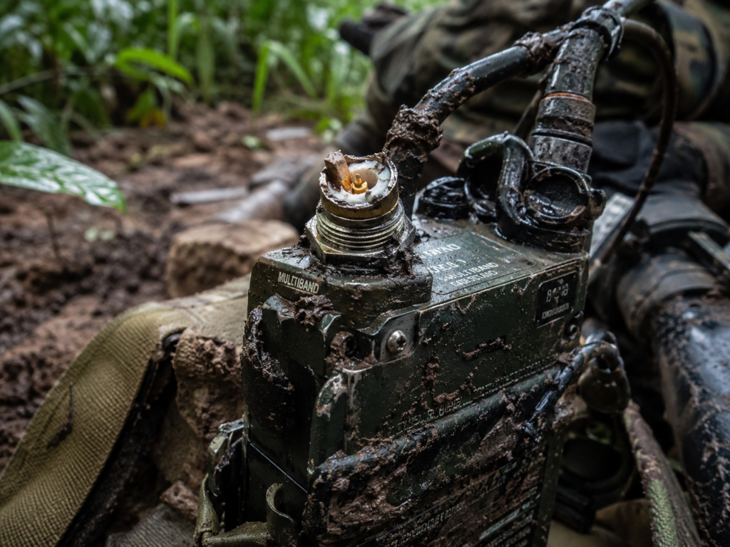
Physics of Antenna Failure in Tactical Operations Infantry radio RF front-end architectures face brutal mechanical realities on active battlefields. Operators crawl through thick foliage dragging communication gear against unyielding physical obstacles constantly. A rigid whip antenna catching on a concrete doorway frequently shears off completely right at its base connector. Such catastrophic mechanical failure severs a radiating element permanently. Your output port impedance instantly transforms from a matched 50-ohm system into a pure open circuit. Pressing a push-to-talk button under these specific circumstances unleashes full forward power directly into a mismatched void. Electromagnetic waves cannot radiate outward into empty space without a properly tuned resonant metallic structure. You might be wondering: where does all that generated RF energy actually go? Energy conservation physics dictates unradiated microwave power must travel backward along a coaxial transmission line toward its source origin. This high-amplitude standing wave slams hard into your final stage power amplifier transistors. Gallium Nitride semiconductor devices possess exceptionally high current density but they cannot absorb 100 watts of continuous reflected energy safely. Rapid internal heat generation expands semiconductor dies unevenly causing micro-cracking and total component destruction rapidly. The resultant smoke and sudden silence leave infantry units completely isolated during active fire engagements. Field engineers reporting from desert operations documented numerous cases involving crushed cables creating dead short circuits. A tank tread rolling over a deployed antenna feedline flattens dielectric separators bridging center conductors directly onto ground shields. This zero-ohm impedance condition generates a similar 100% total reflection returning back into a vulnerable module. Both open and shorted fault states cause identical catastrophic thermal failures inside unprotected transmission equipment. We measure mismatch severity using a Voltage Standing Wave Ratio meter observing spikes far exceeding safe operational thresholds. Your entire field communication link relies entirely upon maintaining that delicate 50-ohm balance continuously.
Infantry Radio Environment Stressors | Failure Mode | Impedance Shift | RF Consequence
— | — | — | —
Antenna snapping off at base connector | Physical Open Circuit | Infinity ohms | 100% Total Reflection
Cable crushed by heavy vehicle tracks | Coaxial Short Circuit | Zero ohms | 100% Total Reflection
Foliage covering radiating elements | Severe Detuning | Variable mismatch | High VSWR Return Loss
Saltwater immersion during beach landings | Dielectric Shorting | Near zero ohms | Heavy Power Dissipation
Architecture Design and Thermal Runaway Mechanisms Commercial off-the-shelf amplifiers completely lack robust architectural safeguards required for combat infantry radio RF front-end applications. Many junior designers assume a simple software-based VSWR polling loop provides adequate protection against load mismatches. That naive assumption represents a fatal physical flaw when dealing with fast-acting high-power microwave transients. Software control loops require millisecond-scale CPU processing time before commanding a physical power rollback. Reflected RF energy destroys unprotected transistor junctions within mere microseconds during a full 100W transmission event. The voltage standing wave ratio peaks create massive voltage swings exceeding device physical breakdown limits. Simultaneously high current nodes generate concentrated hot spots deep inside compact amplifier packaging. Thermal resistance between a semiconductor die and your external heat sink creates a dangerous conductive bottleneck. This is where it gets interesting: standard thermal mitigation cooling strategies fail because localized heat generation rates far outpace physical thermal mass dissipation capabilities. The CRF-PA-5700M5900M-100W operates specifically within a tight 5700 – 5900 MHz frequency range demanding precise microwave impedance matching continuously. A sudden mismatch at 5.8 GHz creates intense standing waves interacting destructively with internal ceramic matching networks. Your entire BOM component selection strategy must prioritize hardware-level autonomous protective analog circuits over slow digital software interventions. Without integrated ferrite isolators or ultra-fast analog cutoff switches an expensive amplifier merely becomes a disposable consumable component. We analyzed failed third-party units returning from rugged mountain testing environments finding identical melted internal copper traces. High frequency reflections strip foil straight off printed circuit boards due extreme localized current densities. Engineers attempting laboratory component repairs face charred craters where high-power matching capacitors previously resided. Designing military-grade hardware necessitates treating an antenna interface as a highly volatile hostile boundary.
VSWR Condition | Return Loss (dB) | Reflected Power (Watts) | Amplifier Status
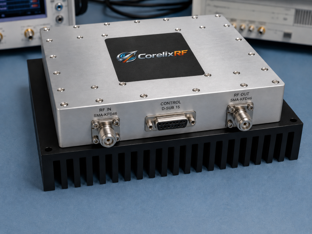
CRF-PA-5700M5900M-100W Hardware Implementation Solving these tactical deployment failures requires specialized RF modules designed deliberately for high-survivability combat scenarios. The CRF-PA-5700M5900M-100W delivers 100 W saturated output power across a critical 5700 – 5900 MHz operating band. We built this specific unit deliberately addressing those infantry radio RF front-end pain points discussed extensively earlier. Its internal architecture includes direct hardware-level detection directional coupler circuits reacting instantly upon severe impedance mismatch events. Pin 13 located on a D-Sub control interface provides a dedicated 5V analog Voltage Alarm signal. This specific VA pin activates immediately when an output RF port experiences a physical open or short circuit condition. System integrators route this analog signal directly into a PA_EN line forcing a hard physical shutdown sequence. What is the real story? This dedicated analog feedback loop bypasses slow digital microcontrollers entirely. Cutting drive bias power happens reliably in under 100 microseconds preventing thermal runaway before semiconductor die temperatures escalate dangerously. Furthermore a rugged sealed 160 × 120 × 25 mm package weighs just 1.4 kg making it highly suitable for tight manpack integration. We utilize heavy-duty SMA-KFD46 connectors rated strictly for high mating cycles and severe physical vibration environments. Engineers no longer need heavy external bulky isolators because our amplifier inherently manages mismatched loads safely internally. Our laboratory stress tests involved deliberately snapping active transmitting antennas while monitoring internal substrate temperatures via infrared cameras. A hardware protection circuit tripped fast enough keeping an amplifier well below its 85-degree Celsius storage limit. This built-in ruggedness fundamentally changes how system designers approach portable high-power microwave link budgets.
Parameter | Specification Limit | Trigger Condition | System Action
Thermal Dissipation and Power Management Tactical communication gear relies entirely upon portable lithium battery sources experiencing wild voltage discharge fluctuations constantly. The CRF-PA-5700M5900M-100W accommodates a wide DC supply voltage range spanning from 24 to 32V with a 28V nominal target. Supplying 100 watts of raw RF power necessitates pulling up to 20A operating current during peak transmission bursts. Managing this massive DC energy transfer requires meticulous mechanical thermal network planning across an entire chassis. Heat accumulation acts as a primary physical degradation vector for any high-power semiconductor device deployed outdoors. A snapped radio antenna causing total signal reflection multiplies internal heat generation exponentially inside a sealed enclosure. Our engineering design includes Pin 12 serving as a dedicated over-temperature analog shutdown alarm. Ready for the good part? This thermal protection operates fully autonomously shutting down RF drive bias if chassis temperatures exceed safe predefined limits. A core unit operates reliably across extreme environments from -40 up to +60 degrees Celsius ambient air temperature. Integrators must clamp a flat module base firmly onto an external heat sink optimized for passive convective cooling. Pin 14 continuously outputs a live analog voltage scaling precisely at 10mV per degree Celsius. Designers utilize this thermal telemetry feeding dynamic fan speed controllers or triggering early warning indicators on operator LCD screens. Every thermal interface material layer requires careful thickness calculation preventing heat pooling under main power amplification stages. We tested this configuration operating continuously inside a 50-degree Celsius environmental chamber verifying absolute stability.
Pin Number | Designation | Function Description | Integration Note
Front-End Matching Network and BOM Selection Building a resilient infantry radio RF front-end demands strict engineering scrutiny during your initial BOM selection phase. Engineers frequently select substandard coaxial cables or fragile commercial connectors trying desperately hitting aggressive budget targets. Those initial cost savings evaporate instantly when a single mechanical point of failure destroys your main power amplifier. Integrating a CRF-PA-5700M5900M-100W dictates utilizing high-grade SMA-KFD46 mating components strictly adhering military specifications. Mismatch reflection errors often originate directly at a connection interface before ever reaching an actual external antenna element. A poorly torqued coaxial connector introduces severe electrical phase shifts and intense localized contact heating. You must implement a fail-safe matching logic control block utilizing our provided RS485 communication bus architecture. Pins 1 and 8 handle bidirectional serial data allowing continuous monitoring tracking forward and reversed RF power indicators. But here is the kicker… true combat reliability comes directly from analog hardware redundancy. While a digital RS485 bus provides excellent telemetry data your primary physical defense remains our analog alarm pins. Tying Pin 13 directly into a fast hardware interrupt guarantees module survival during extreme combat damage scenarios. Designing an internal transmission line requires choosing low-loss PTFE dielectric materials maintaining tight 50-ohm impedance traces rigidly. Any minor physical layout deviation creates parasitic reflections compounding alongside external antenna damage. We mandate a maximum input VSWR limit held strictly below 1.5 preventing cascading mismatch instability across multiple cascaded stages.
Subsystem | Key Requirement | CRF-PA-5700M5900M-100W Feature | Engineering Benefit
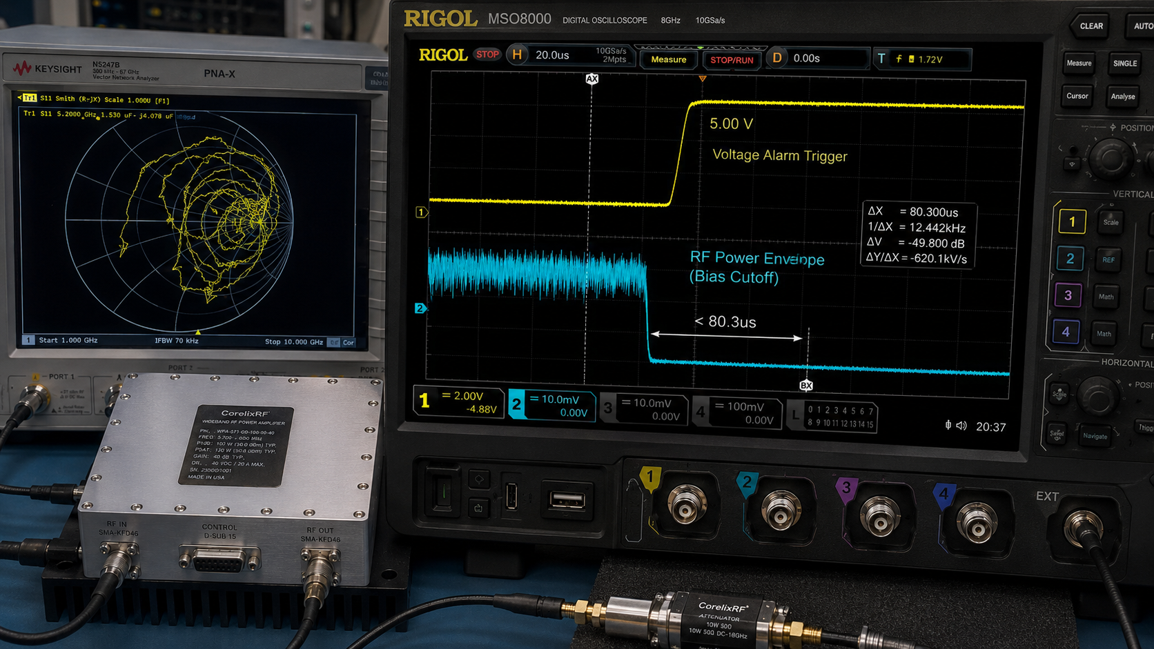
Laboratory Verification and VNA Diagnostics Verifying physical system robustness demands rigorous testing procedures using precision Vector Network Analyzers during early prototyping phases. Engineers simulating infantry radio RF front-end faults frequently observe strange high-frequency degradation on standard commercial test equipment. A sudden short circuit condition causes a VNA Smith chart trace spinning wildly indicating massive phase instability. Injecting small signal sweeps across a 5700 – 5900 MHz band reveals how weak matching networks collapse under stress. The CRF-PA-5700M5900M-100W maintains strict structural integrity shielding internal circuits from external load variations effectively. We utilize Pin 10 providing a 0-3V analog forward power indicator correlating perfectly with laboratory spectrum analyzer measurements. Connecting Pin 7 allows simultaneous monitoring tracking reversed RF power returning from a damaged load simulator. Here is the deal: observing these twin analog signals using a high-speed oscilloscope paints a clear temporal picture. When an artificial open circuit triggers reflection voltage spikes sharply hitting an internal coupler. Pin 13 alarm goes high shutting off bias gate current precisely within 100 microseconds. An oscilloscope trace drops flat proving hardware protection activates fast enough preventing permanent GaN transistor damage. This level of verifiable diagnostic transparency gives system integrators absolute confidence deploying hardware into hostile operational theaters. You eliminate guesswork knowing physical protection mechanisms trigger autonomously independent from main CPU software status.
Final Engineering Assessment Designing a tactical infantry radio RF front-end requires acknowledging harsh physical realities dominating battlefield deployments. Relying on slow software polling loops attempting mitigating instantaneous reflected power from a snapped antenna guarantees hardware destruction. The CRF-PA-5700M5900M-100W integrates pure analog hardware VSWR protection shutting down microwave transmission before catastrophic thermal runaway occurs. You must stop replacing burnt amplifiers caused by inevitable physical antenna damage. Contact the CorelixRF engineering team today requesting our complete technical integration documentation.
Frequently Asked Questions
Q1: What is an infantry radio RF front-end mismatch?
An impedance mismatch occurs when a physical antenna breaks or disconnects completely. A transmission line sees an open circuit causing all forward RF power reflecting backward toward an amplifier.
Q2: How does a CRF-PA-5700M5900M-100W VSWR protection work? Our amplifier features an internal directional coupler detecting severe reflected energy spikes instantly. It triggers a 5V logic high signal on Pin 13 allowing engineers disabling drive current immediately.
Q3: Why do standard commercial amplifiers fail during open circuit events? Standard commercial amplifiers lack fast analog cutoff switches completely. Reflected 100W energy creates extreme voltage peaks causing massive localized heating destroying internal GaN transistor junctions within microseconds.
Q4: What voltage is required for a CRF-PA-5700M5900M-100W? A module operates safely between 24V and 32V DC continuously. A nominal 28V supply handles peak operating currents reaching up to 20A during full 100W saturated output.
Q5: How fast is a hardware shutdown mechanism? Using a dedicated PA_EN pin driven by our hardware voltage alarm allows complete system shutdown in under 100 microseconds preventing any permanent thermal damage.
Define open-circuit protection before field deployment
For open-circuit and antenna-break conditions, specify foldback behavior, shutdown threshold, recovery logic, alarm output, timing and test evidence. This helps avoid vague VSWR protection claims.
Recommended next step: send the operating band, target output power, duty cycle, thermal or load condition, control interface, protection behavior and required FAT documents. CorelixRF can review this RF amplifier VSWR protection for open circuits requirement against standard amplifier platforms, RF front-end options and custom engineering constraints.