
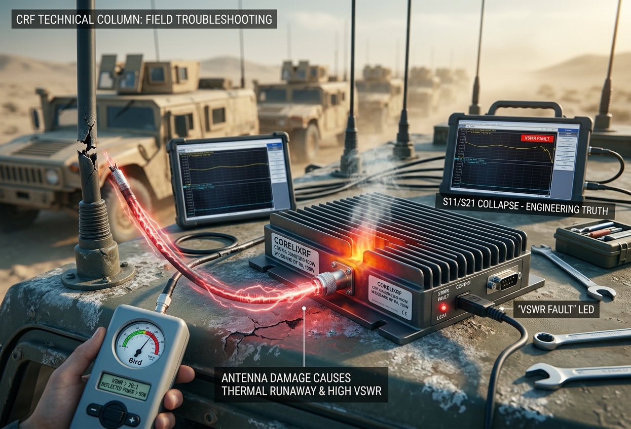
Tactical convoy operators constantly encounter catastrophic hardware failures when maneuvering tactical vehicles across hostile terrain. Sudden physical impacts snap roof-mounted antennas immediately causing total signal reflection destroying standard electronics. CorelixRF engineers eliminate these deadly thermal runaway events utilizing purpose-built wideband amplifiers. [Field Troubleshooting] Hidden Failures in Convoy Jammer Environments: Reflected Energy Reversal and Thermal Runaway Triggered by Accidental Antenna Damage or Open Circuits exposes hard engineering truths. We deliver proven survival solutions.
Use high-VSWR thermal runaway diagnosis to reduce RF hardware risk
High-VSWR thermal runaway should trigger a review of amplifier protection, antenna matching, reflected-power handling, cooling margin and acceptance tests before procurement.
1. How do convoy jammer systems fail under severe vibration?
Physical Degradation Factors
● Mechanical stress on RF cables
● Intermittent connector contact
● Catastrophic antenna breakage
Here’s the deal. Tactical operations involve heavy armored vehicles traversing uneven terrain at high speeds causing extreme mechanical shock across all installed electronic payloads. Roof-mounted antennas constantly strike low-hanging tree branches or urban structures violently stressing coaxial feedlines over prolonged operational periods. Such mechanical abuse frequently results in cracked solder joints inside base connectors or complete physical shearing of radiating elements. When an antenna breaks physically mid-transmission an instantaneous open circuit appears at radio frequency output ports immediately. Forward power traveling along transmission lines suddenly finds no radiation path bouncing directly back toward source components instantly. This sudden impedance mismatch triggers immediate thermal alarms within vehicle cabins flashing high VSWR warnings across operator control panels. Field engineers analyzing these failures post-mission typically observe severe high-frequency collapse on network analyzer traces indicating internal component degradation. Standard commercial off-the-shelf equipment cannot survive such brutal operational realities requiring purpose-built hardware capable handling absolute worst-case conditions.
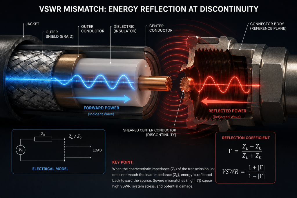
2. Why do open circuits cause extreme reflected energy reversal?
Transmission Line Dynamics
● Voltage standing wave ratio spikes
● Phase alignment wave interference
● Extreme voltage destroying transistors
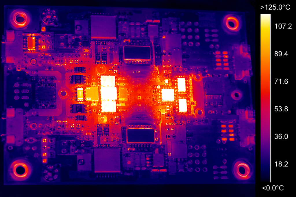
What’s the real story? Understanding transmission line theory remains absolutely critical for diagnosing catastrophic field failures involving high-power microwave transmitters. When load impedance perfectly matches source impedance maximum power transfer occurs without any energy bouncing backward along coaxial cables. However an open circuit creates an infinite mismatch driving reflection coefficient magnitude straight toward unity almost instantaneously. All forward power generated by amplifier stages reverses direction slamming back into output matching networks with devastating force. Depending upon physical cable length phase relationships between forward waves and reflected waves align constructively at specific nodes. This constructive interference generates massive transient voltage peaks far exceeding maximum drain breakdown ratings belonging power transistors. LDMOS or Gallium Nitride devices operating under continuous wave conditions face immediate physical destruction unless protective circuitry reacts within microseconds. Engineers troubleshooting these specific scenarios often find blown matching capacitors or completely charred printed circuit board traces inside broken units.
Reflected Power Dynamics Overview
| Mismatch Condition | Reflection Coefficient | Power Reflected | Component Stress Level |
| Perfect Match 50 ohms | 0.00 | 0% | Normal operation |
| Minor Damage | 0.33 | 11% | Moderate heating |
| Severe Damage | 0.80 | 64% | Critical thermal limits |
| Complete Open Circuit | 1.00 | 100% | Catastrophic failure risk |
3. What physical mechanisms drive thermal runaway during antenna damage?
Semiconductor Breakdown Sequence
● Inefficient power dissipation
● Junction temperature exponential rise
● Positive feedback loop generation
But here’s the kicker. Transistors transforming direct current into radio frequency power generate substantial waste heat even during perfectly matched nominal operation. Introducing massive reflected energy forces these delicate semiconductor junctions into highly inefficient operational regions causing immediate localized heating. Normal cooling systems designed handling matched loads suddenly face overwhelming thermal burdens unable extract heat fast enough. Silicon or GaN material structures possess specific thermal resistance properties dictating how rapidly die temperatures elevate under extreme stress. Elevated temperatures decrease carrier mobility increasing internal electrical resistance which ironically generates even more localized heat creating vicious positive feedback loops. This phenomenon known scientifically as thermal runaway permanently alters device characteristics degrading amplifier performance permanently without warning. Field technicians replacing burnt modules routinely observe severe discoloration around output matching networks confirming massive localized temperature excursions. Purpose-built military hardware must employ massive thermal margins preventing sudden destructive runaway events during critical tactical deployments.
4. How can field engineers diagnose VSWR anomalies accurately?
Rugged Measurement Techniques
● Utilizing precision directional couplers
● Analyzing digital oscilloscope envelopes
● Measuring reverse power precisely
You might be wondering. Isolating root causes behind tactical jamming vehicle failures requires rigorous diagnostic methodologies utilizing specialized measurement equipment reliably. Frontline technicians cannot rely blindly upon generic system fault lights demanding deeper quantitative analysis using ruggedized field instruments. Inserting high-power directional couplers between amplifier outputs and antenna feeds allows safe extraction detailing precise forward minus reverse power ratios. Connecting fast digital oscilloscopes directly monitoring coupler coupled ports reveals instantaneous transient voltage spikes occurring during vehicle movement. Cheap commercial standing wave meters lack sufficient bandwidth capturing brief intermittent connection losses occurring under heavy mechanical vibration. Advanced engineers prefer sweeping compromised transmission lines using portable vector network analyzers pinpointing exact distance fault locations visually. Detecting an open circuit exactly two meters away matches physical cable routing confirming antenna base connector shear points perfectly. True root cause analysis separates component manufacturing defects from actual environmentally induced physical damage saving thousands replacing wrong parts.
Field Diagnostic Tools Comparison
| Instrument Type | Bandwidth Capability | Transient Detection | Primary Use Case |
| Basic VSWR Meter | Narrowband limited | Extremely poor | Routine stationary checks |
| Directional Coupler | Ultra-wideband | Excellent | Real-time dynamic monitoring |
| Digital Oscilloscope | High frequency | Outstanding | Peak voltage capturing |
| Portable VNA | Full spectrum | Not applicable | Cable fault locating |
5. Why do standard commercial amplifiers fail during convoy operations?
Structural Design Weaknesses
● Insufficient internal thermal mass
● Weak printed circuit boards
● Lack protective logic circuits
This is where it gets interesting. Vendors selling inexpensive commercial radio equipment often specify performance using highly controlled laboratory conditions ignoring brutal field reality. Commercial modules utilize thin lightweight aluminum heatsinks incapable absorbing sudden massive thermal shocks generated by complete load disconnects. Their printed circuit boards use standard FR4 materials which literally melt or delaminate when subjected intense radio frequency hotspots. Furthermore standard designs prioritize maximum output efficiency neglecting crucial high-speed active protection circuits capable shutting down driving stages instantly. When an armored truck smashes through heavy foliage snapping its primary jamming mast cheap commercial boxes literally catch fire internally. Tactical electronic warfare missions require continuous operation demanding systems built specifically anticipating inevitable physical component destruction impacting external loads. Relying upon standard commercial grade components jeopardizes human lives rendering entire defensive jamming umbrellas completely useless mid-mission. True engineering demands acknowledging extreme operational variables anticipating worst-case hardware survival scenarios continuously.
6. What makes the CRF-PA-30M512M-100W withstand extreme mismatch?
CorelixRF Hardware Resilience
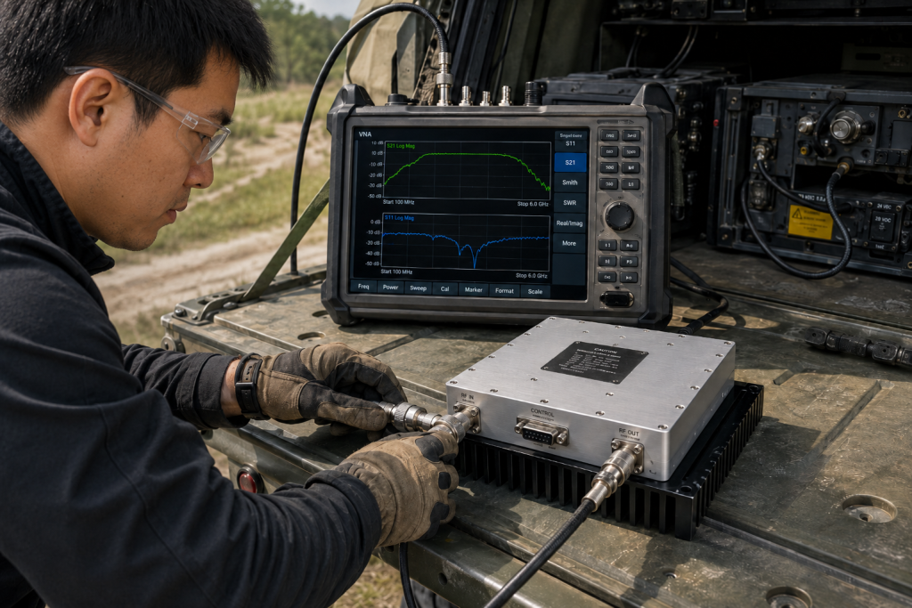
● Wideband operational frequency coverage ● High-reliability ruggedized metallic housing ● Guaranteed standing wave tolerances Ready for the good part? Addressing these precise catastrophic failure modes requires deploying hardened technology like CorelixRF wideband radio frequency power amplifiers. The specific CRF-PA-30M512M-100W module operates reliably across a massive 30-512 MHz frequency range ensuring continuous tactical spectrum dominance. This rugged unit delivers 100 W rated output power effortlessly driving heavy tactical antennas under severe operational conditions. Engineers specifically designed its internal architecture handling continuous wave and saturated output power types maintaining absolute output stability. Its robust matching networks guarantee survival even when facing output VSWR conditions reaching ≤2.0:1 without sustaining internal damage. Achieving an impressive 50 dB typical gain requires only minor input drive levels making system integration remarkably straightforward. Housed inside a heavy-duty 200x158x25 mm chassis this module dissipates heat highly efficiently utilizing specialized internal thermal pathways.
CRF-PA-30M512M-100W Core Specifications
| Parameter Description | Rated Value | Engineering Significance |
| Frequency Range | 30-512 MHz | Covers primary tactical communications |
| Output Power | 100 W CW | Delivers required jamming effectiveness |
| Typical Gain | 50 dB | Allows low power exciter usage |
| Output VSWR Tolerance | ≤2.0:1 | Survives severe antenna degradation |
7. How does active mismatch protection prevent hardware destruction?
Intelligent Monitoring Systems
● High-speed current draw monitoring ● Voltage breakdown avoidance logic ● Extreme ambient temperature resilience Let that sink in. True ruggedness demands intelligent internal monitoring systems reacting far faster than human operators ever could manually. The CRF-PA-30M512M-100W continuously monitors its 28 VDC supply voltage tracking power consumption during violent dynamic load changes. Current consumption remains strictly clamped below ≤18 A preventing catastrophic power supply collapses during extreme transmission line mismatches. Whenever reflected energy spikes abnormally internal protective logic scales back forward drive maintaining safe semiconductor junction operating parameters instantly. This proactive throttling mechanism prevents destructive voltage peaks from destroying expensive final stage Gallium Nitride devices unexpectedly during operations. Furthermore this precise module operates flawlessly across brutal ambient temperatures ranging from -40 up through +85 °C. Integrating such comprehensive autonomous protection ensures continuous mission availability protecting critical jamming assets during hostile kinetic engagements constantly.
8. What role do specific RF connectors play in system reliability?
Mechanical Interface Stability
● Securing physical electrical connections ● Preventing intermodulation distortion generation ● Handling massive continuous power Why does this matter? Mechanical interfaces represent prime failure points across any tactical vehicle deployed within high-vibration combat environments globally. Flimsy commercial plugs simply vibrate loose introducing intermittent impedances causing immediate massive reverse energy spikes internally degrading system performance. The CorelixRF solution addresses these vulnerabilities utilizing specialized high-reliability interfaces specifically implementing SMA-Female RF input connectors. For massive power delivery sections engineers chose rugged N-Female RF output connectors guaranteeing solid continuous electrical contact. These heavy-duty threaded interfaces withstand severe lateral mechanical shocks preventing center pin fretting corrosion ruining critical transmission lines permanently. Integrating a secure DB9 control connector ensures remote telemetry signals reach vehicle management computers without physical interruption. Proper torqueing procedures combined with robust connector selections drastically reduce unpredicted field failures saving invaluable troubleshooting time frontline.
Physical Interface Specifications
| Connection Port | Connector Type | Operational Advantage |
| RF Input Port | SMA-Female | Secure low-power locking |
| RF Output Port | N-Female | High-power vibration resistance |
| Telemetry Control | DB9 interface | Rugged data communication |
| Cooling Interface | Air Cooling chassis | Maintenance-free thermal management |
9. How do we verify module survival using rugged field instruments?
Empirical Validation Processes
● Sweeping amplifier gain flatness ● Measuring system harmonic distortion ● Confirming input matching stability Think about it. Verifying operational readiness following severe antenna strikes requires objective quantifiable data beyond simple green dashboard lights. Technicians connect precision analyzers capturing representative swept measurements verifying critical gain S21 parameters across full operational spectrums successfully. The CRF-PA-30M512M-100W demonstrates extraordinary stability maintaining strict gain flatness tight tolerances around ≤1.8 dB even post-trauma. Field teams analyze input match SWR S11 traces confirming values remain solidly near 1.3 typical avoiding unwanted reflections. Generating clean spectrums remains vital hence engineers strictly verify harmonics stay below extremely rigorous ≤-10 dBc thresholds securely. Furthermore pushing spurious emissions violently downward hitting ≤-60 dBc prevents unintended self-jamming degrading adjacent friendly communication networks. Uploaded instrument screenshots retain original validation data proving these hardware modules exceed demanding baseline electrical characteristics consistently.
10. Why should system integrators adopt ruggedized wideband amplifiers?
Strategic Integration Advantages
● Ensuring absolute mission success ● Reducing lifetime maintenance costs ● Streamlining vehicle payload integration Want to know the best part? Tactical electronic warfare systems demand uncompromised reliability demanding strictly qualified foundational building blocks fundamentally. CorelixRF delivers immense value through strict compliance respecting rigorous ISO 9001 and GJB 9001C quality frameworks entirely. System integrators benefit dramatically implementing a compact unit weighing merely ≤1.4 kg optimizing overall vehicle payload dynamics. Customization options allow tailoring specific custom frequency bands or specialized control interfaces meeting highly classified project requirements perfectly. Dedicated engineering teams provide detailed feasibility reviews within 48 hours accelerating rapid prototyping development cycles tremendously saving resources. Providing comprehensive MTBF reliability data alongside environmental validation data further supports complex military procurement review processes seamlessly. Adopting genuinely ruggedized hardware eliminates unpredictable field failures ensuring continuous overmatching capabilities protecting deployed personnel absolutely.
Quality and Integration Framework
| Qualification Type | Standard / Metric | System Integrator Benefit |
| Civilian Quality | ISO 9001 | Assured manufacturing consistency |
| Military Quality | GJB 9001C | Guaranteed combat-ready reliability |
| Safety/Emissions | CE/FCC compliant | Safe electromagnetic environment |
| Physical Weight | ≤1.4 kg | Excellent payload optimization |
[Field Troubleshooting] Hidden Failures in Convoy Jammer Environments: Reflected Energy Reversal and Thermal Runaway Triggered by Accidental Antenna Damage or Open Circuits conclusively proves true engineering resilience. Surviving extreme transmission line mismatch demands purpose-built ruggedized hardware avoiding catastrophic field failures. Protect frontline personnel replacing fragile commercial units utilizing proven CorelixRF components. Contact specialized engineering teams obtaining complete validation data supporting upcoming tactical vehicle integrations immediately.
FAQ Section
Q1: What is reflected energy reversal?
Reflected energy reversal occurs whenever broken transmission lines force forward traveling radio frequency waves backward causing massive destructive voltage standing wave ratio spikes inside transmitter stages.
Q2: How does thermal runaway work?
Thermal runaway happens when excessive localized heat degrades semiconductor performance increasing internal resistance which generates even more waste heat creating continuous destructive positive feedback loops.
Q3: Why fail commercial amplifiers during tactical operations?
Commercial amplifiers fail because vendors utilize cheap fragile printed circuit boards lacking adequate thermal mass preventing survival during severe dynamic mechanical shock impacting vehicle antennas.
Q4: How performs the CRF-PA-30M512M-100W under severe mismatch? This specialized rugged module sustains extreme load mismatches featuring output tolerances reaching ≤2.0:1 safely dissipating excess thermal loads preventing catastrophic component failure completely.
Q5: What connectors ensure stable vehicle integration? Engineers utilize threaded SMA-Female input ports alongside heavy-duty N-Female output connectors guaranteeing unbroken electrical contact preventing intermittent reflection spikes during violent high-speed maneuvers.
Turn VSWR behavior into factory acceptance evidence
High VSWR protection should be defined with mismatch scenario, foldback or shutdown threshold, recovery logic, alarm output, thermal limit and FAT evidence. This makes protection claims measurable for procurement.
Recommended next step: send the operating band, output power target, duty cycle, load condition, control interface, protection or thermal limits and required FAT documents. CorelixRF can review this How to Diagnose RF Amplifier Thermal Runaway from High VSWR? requirement against standard RF amplifier platforms, RF front-end options and controlled customization paths.