
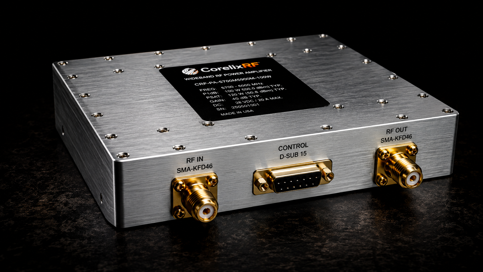
Field Troubleshooting: Convoy Jammer Signal Anomalies—Antenna Damage, Reflected Power, and Thermal Runaway. Jamming systems frequently suffer unexpected shutdowns during mobile operations. This leaves VIP vehicles defenseless against remote threats. We present an engineering-grade solution for protecting RF amplifiers. CorelixRF delivers battle-tested hardware resolving these catastrophic failures. Here’s the deal: proper diagnostic techniques save lives.
1. What Triggers Convoy Jammer Signal Failures?
Identifying initial dashboard alarms
System operators often observe sudden drop-offs in transmission capability. Control panels flash VSWR warnings immediately following physical impacts. Warning lights indicate severe faults happening along transmission lines. Operators working inside armored transports rely heavily on jamming curtains. Any momentary lapse allows hostile signals through. Equipment durability remains absolutely non-negotiable here. A single damaged component compromises an entire convoy mission. We mandate rigorous mechanical testing protocols.
Physical realities of vehicular environments
Tactical vehicles traverse extremely rough terrain daily. High-frequency vibrations loosen SMA connectors connecting power stages. Tree branches constantly strike external roof-mounted antennas. Mud packs tightly around exposed RF fittings causing shorts. Continuous shock waves travel through vehicle frames damaging internal boards. Military convoys operate far away from clean laboratory environments.
Operator reports regarding field performance
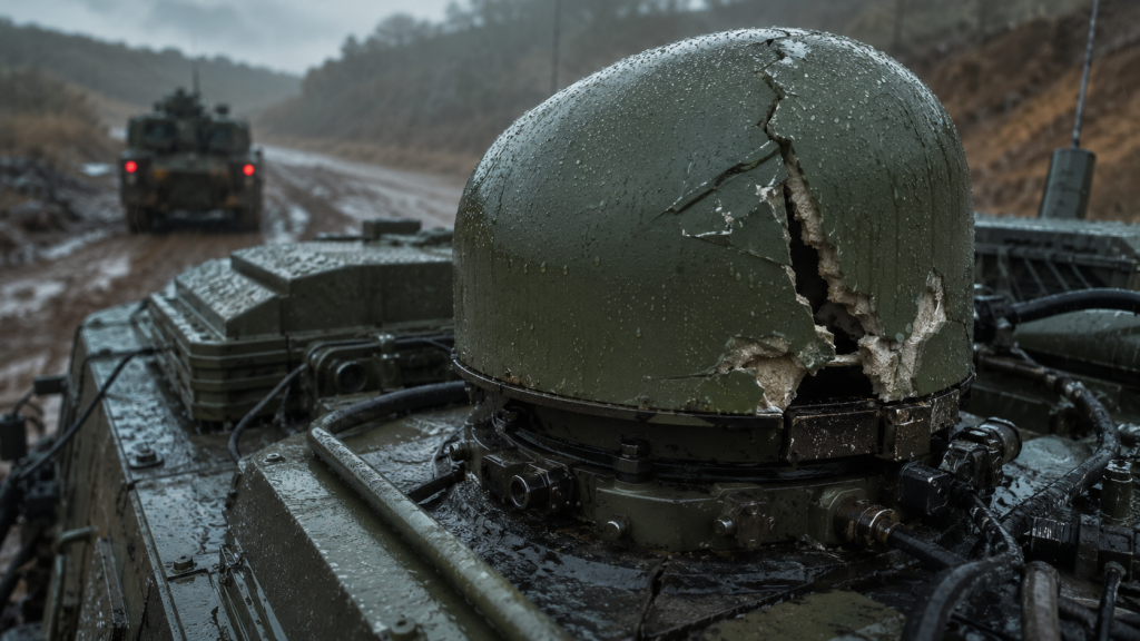
Field technicians document severe range reductions during deployments. You might be wondering: what physically breaks? Broken radomes expose internal radiating elements. Moisture ingresses into coaxial cables rapidly. A previously matched 50-ohm system becomes an open circuit. These mechanical failures create massive electrical problems. We must analyze this mismatch using proper instruments. Finding root causes requires understanding microwave propagation theory.
2. Why Does Antenna Damage Cause Reflected Power?
Impedance mismatch fundamentals
RF energy requires a continuous 50-ohm path. A damaged antenna alters this characteristic impedance drastically. Forward power hits this discontinuity barrier. The travelling wave cannot proceed outward into free space. Basic electromagnetic theory dictates energy conservation during transmission. That energy must find an alternative path quickly.
Reverse energy propagation paths
Energy cannot simply vanish into thin air. It bounces back toward your amplifier module. This reverse wave travels down coaxial feedlines. What’s the real story? The final stage transistors absorb this returning force. They were designed only for forward amplification tasks. Absorbing high power reverse waves stresses internal silicon junctions.
VNA measurements of damaged radomes
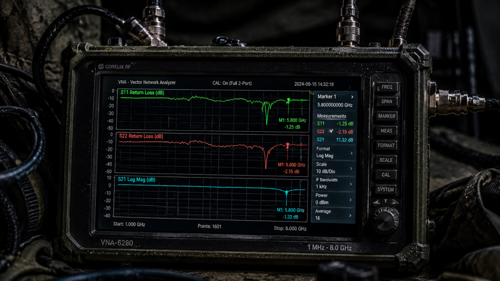
Connecting a Vector Network Analyzer reveals alarming truths. The return loss curve collapses entirely. We see 0 dB return loss at 5.8 GHz. A normal system shows better than -15 dB. This means 100% reflection occurs instantly. 100W of raw power returns home. Engineers utilizing time-domain reflectometry can pinpoint exact fault locations. Cable faults appear clearly on instrument displays. A sharp impedance spike indicates physical cable severing. Operators must replace damaged cables immediately upon detection. Allowing a faulty feedline destroys active electronics eventually. We strictly advise against bypassing system interlocks during operation.
3. How Does Reverse Energy Lead Toward Thermal Runaway?
Heat dissipation limits within amplifier modules
Gallium Nitride transistors generate significant heat normally. They convert DC power into RF energy. Reflected power forces them into acting as dummy loads. Heat sinks reach boiling temperatures rapidly. Internal thermal sensors trigger emergency shutdown protocols. A poorly designed thermal path guarantees component vaporization. Our engineers analyze thermal images identifying hot spots. Superior baseplate materials spread thermal loads efficiently.
Thermal cascading effects on transistor junctions
Junction temperatures spike within milliseconds. The cooling system cannot extract heat fast enough. Efficiency plummets while current draw skyrockets. This is where it gets interesting: system failure happens rapidly. High temperatures increase semiconductor resistance further. Increased resistance generates even more thermal energy. This runaway loop destroys power amplifiers permanently.
Real-world oscilloscope capture examples
Monitoring current with an oscilloscope shows massive transients. A normal 16A draw spikes past 25A. The chassis temperature climbs 10 degrees per second. Solder joints melt inside standard commercial amplifiers. Silicon physically degrades under these extreme conditions. Only robust protection circuits prevent permanent destruction. Field mechanics often ignore warning lights during active engagements. Operating compromised hardware accelerates catastrophic failure rates.
4. What Are The Specific Challenges For 5700-5900 MHz Bands?
Wavelength implications on connector strain The 5.8 GHz band features very short wavelengths. Even slight mechanical misalignments cause severe phase shifts. SMA-KFD46 connectors require precise torque specifications. Loose connectors create micro-gaps altering physical dimensions. These gaps reflect high frequency signals heavily. We specify calibrated torque wrenches during vehicle integration.
High-frequency material degradation
Low-quality Teflon insulators warp under continuous thermal stress. This warping alters capacitance values unpredictably. Ready for the good part? Proper material selection mitigates this risk entirely. CorelixRF utilizes advanced aerospace grade dielectrics. These materials maintain stable electrical properties across wide temperatures. Military vehicles lack climate controlled electronics bays. Ambient temperatures routinely exceed 60 degrees Celsius. Amplifiers must survive these brutal thermal environments. Dielectric constants change as temperatures rise. Mismatched dielectrics introduce additional standing waves.
Environmental factors impacting microwave links
Salt fog heavily corrodes exposed brass fittings. Corroded threads create micro-arcing during high power transmission. This arcing generates broad spectrum noise floors. A spectrum analyzer will display this elevated noise clearly. We use gold-plated contacts preventing surface oxidation. We rigorously screen every component facing environmental extremes. Our engineers utilize advanced electromagnetic simulation software. Simulating real world stress ensures reliable field operation.
5. How Can Engineers Diagnose Open Circuits In The Field?
Utilizing directional couplers effectively
Field technicians must insert inline directional couplers. These passive devices sample forward and reverse power accurately. Measuring these twin power levels reveals actual system health. A high reverse reading confirms immediate downstream faults. Maintenance crews carry portable power meters accessing coupler ports. Fast readings allow rapid tactical decisions under fire. We train personnel reading raw dBm values confidently.
Interpreting spectrum analyzer noise floors
Connect a portable spectrum analyzer observing broadband noise. Broken connectors often generate intermittent crackling interference. Now consider this: an unstable baseline indicates severe physical damage. Normal operation produces flat and stable spectral traces. Sweeping a frequency span uncovers hidden intermodulation products. Loose metal junctions act like crude diode mixers. They create false signals masking legitimate jamming frequencies.
Time-domain reflectometry techniques
Modern testing gear includes TDR capabilities. TDR sends short pulses down your coaxial cable. The instrument times returning echoes finding exact fault distances. Knowing exact failure locations speeds up battlefield repairs. Our training manuals detail these diagnostic procedures comprehensively. Fast troubleshooting minimizes operational downtime significantly. Ground crews swap specific cables rather than guessing blindly. Efficient diagnostics save vital resources during extended missions.
6. What Makes CRF-PA-5700M5900M-100W Suitable For Convoy Protection?
CorelixRF design philosophy implementation We designed the CRF-PA-5700M5900M-100W specifically targeting vehicular environments. It operates across 5700 through 5900 MHz reliably. This narrowband focus maximizes efficiency and output power. It delivers 100W rated output power consistently. Our engineers prioritize survival over mere benchmark specifications. We build hardware surviving actual battlefield conditions. The 160 by 120 millimeter chassis fits cramped racks perfectly.
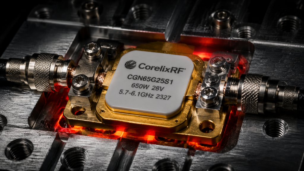
Analyzing forward and reverse power indicators Our hardware includes dedicated telemetry pins. Pin 10 outputs forward power analog voltages. Pin 7 provides reverse power readings directly. Here’s the kicker system controllers monitor these values instantly. Microcontrollers can execute safety algorithms based upon telemetry. Analog voltages ranging from 0 to 3 Volts represent power levels. External computers map these voltages translating them into Watts. This provides transparent visibility regarding RF output stages.
Examining Pin 13 VA Alarm functionality Pin 13 serves as an ultimate hardware failsafe. It throws a 5V alarm flag immediately. This flag triggers whenever outputs face open circuits. It also activates during complete short circuits. It acts faster than software-based polling loops. This instant reaction saves internal GaN devices. Hardwired logic gates process this fault under 100 microseconds. No operating system crash delays this critical protective action.
7. How Does The Internal Protection Circuitry Function?
VSWR monitoring mechanics
Internal directional couplers sample RF streams continuously. Analog comparators evaluate forward versus reflected voltages. High reflected energy crosses predefined safety thresholds. Precision resistor networks set these tripping points accurately. Factory calibration ensures consistent protection across varying temperatures. We test every unit driving intentional short circuits.
Automated shutdown sequences Once thresholds breach, internal logic gates activate. The amplifier disables bias voltages within 100 microseconds. RF output drops practically zero instantly. What’s the catch? You must reset it manually. Pin 6 handles external alarm resets. Sending a pulse clears locked alarm states. This prevents automatic restarting into a damaged antenna. Continuous restarting creates deadly thermal pumping effects. Operators must acknowledge faults before re-engaging jamming curtains.
Thermal sensor integration Pin 12 provides an over-temperature alarm signal. It goes active shutting down operations safely. Pin 14 outputs real-time chassis temperatures. It scales at 10 millivolts per degree Celsius. System integrators read this analog voltage dynamically. They adjust cooling fan speeds matching thermal demands. This prevents thermal limits from ever being breached. Intelligent cooling reduces acoustic signatures during covert operations. Fans run quietly until maximum RF power demands airflow.
8. Why Is Thermal Management Critical At 100W Output?
Baseplate temperature thresholds The CRF-PA-5700M5900M-100W requires strict thermal control. Baseplate temperatures must remain below 60 degrees Celsius. Operating currents reach 20 Amperes during saturation. Twenty amps at 28 Volts equals 560 Watts consumed. Generating 100 Watts RF leaves 460 Watts of pure heat. This massive thermal load demands serious engineering attention. Neglecting thermal budgets guarantees rapid field failures.
Continuous wave operation demands Jamming signals utilize continuous wave transmission formats. CW operation generates maximum possible thermal loads. The module dimensions are 160 by 120 millimeters. You see… this footprint spreads heat effectively. Thick aluminum baseplates transport heat away from active transistors. We machine heat spreaders perfectly flat ensuring maximum contact. Surface roughness degrades thermal transfer efficiency significantly.
Mechanical integration specifications Integrators must mount this unit onto massive heatsinks. Thermal paste application remains an absolute necessity. Uneven mounting surfaces trap microscopic air pockets. These pockets act as thermal insulators destroying components. We recommend utilizing high CFM forced air cooling. Liquid cooling plates offer even better thermal margins. Proper integration guarantees a 30-year operational lifespan. CorelixRF provides complete mechanical outlines aiding system designers.
9. How To Integrate The 15-Pin D-Sub Control Interface?
Real-time telemetry extraction Military systems require constant situational awareness. A standard D-Sub 15-Pin connector handles all signaling. It provides ruggedized connections surviving intense vibration. Gold plated pins prevent intermittent contact issues. Screwing the connector down locks telemetry lines securely. Reliable telemetry feeds battlefield management software accurately. Command centers monitor jammer health miles away.
RS485 communication protocols Pins 1 and 8 support RS485 serial buses. This master-slave architecture allows digital parameter adjustment. Controllers adjust gain across a 20 dB range. Listen to this: step sizes are 0.5 dB precisely. You can interrogate operational voltages remotely. Digital buses reduce heavy analog wiring harnesses. A single twisted pair controls multiple amplifier modules simultaneously. Addressable nodes make complex array integration much easier.
Voltage and current monitoring strategies Pin 2 generates alarms for over-voltage conditions. It activates above 32 Volts protecting internal regulators. Pin 3 flags over-current events exceeding 22 Amperes. These dedicated hardware interrupts prevent power supply failures. Integrators wire these directly into main system PLCs. Fast fault isolation keeps personnel safe during combat. We engineered these safeguards based on hard field lessons.
10. What Are The Long-Term System Reliability Impacts?
Reducing MTBF in combat zones Mean time between failures improves drastically. Using our hardware eliminates common catastrophic failures. Jamming systems remain active protecting troop movements. Defective hardware costs more than mere replacement value. A failed jammer risks entire vehicle convoys entirely. We test parameters against stringent GJB 9001C standards. Quality assurance prevents defective units reaching front lines.
Preventive maintenance schedules
Telemetry allows predictive maintenance instead of reactive repairs. Technicians swap antennas before complete transmission failures. Monitoring Pin 7 voltage trends shows degrading connectors. Truth be told: data driven maintenance saves money. Logistics officers order spare parts based on telemetry trends. Replacing a 50 dollar cable saves a 5000 dollar amplifier. Smart monitoring changes how militaries handle electronic warfare assets.
Upgrading legacy architectures Older jammers lack these sophisticated protection layers. Retrofitting the CRF-PA-5700M5900M-100W modernizes aging fleets. It drops right into existing 28V supply rails. It provides 48 dB typical gain boosting weak signals. We offer custom control interfaces meeting specific needs. Our engineering team reviews feasibility within 48 hours. Modernizing older vehicles improves defensive capabilities quickly. CorelixRF supports integrators through every upgrade phase.
| Compliance Protocol | Implementation Phase | Expected Outcome |
Robust hardware design mitigates antenna damage risks entirely. The CRF-PA-5700M5900M-100W prevents thermal runaway utilizing active telemetry. System integrators building convoy jammers demand this reliability. Contact CorelixRF engineering teams obtaining full technical datasheets. Upgrade your defensive platforms utilizing proven microwave engineering.
Q1: What triggers convoy jammer signal failures?
Antenna damage and loose connectors cause severe impedance mismatches in harsh vehicular environments.
Q2: Why does antenna damage cause reflected power?
Broken radomes create open circuits forcing RF energy backward toward your amplifier module.
Q3: How does reverse energy lead toward thermal runaway?
Reflected power forces final stage transistors absorbing heat beyond their dissipation limits.
Q4: What makes CRF-PA-5700M5900M-100W suitable for convoy protection?
It includes hardware-level VSWR alarms and reverse power telemetry surviving extreme field abuse.
Q5: Why is thermal management critical at 100W output?
Continuous wave jamming generates immense heat requiring proper heatsinks maintaining baseplates below 60 degrees.
Authorized RF engineering and compliance review
For regulated RF systems, this page should be used as an engineering and compliance review path, not as a public deployment checklist. CorelixRF starts with authorization status, operating region, frequency plan, output limit, antenna interface, safety controls, thermal limits and acceptance documents.
- RFQ checklist – send the data buyers usually forget, including band, power, duty cycle, interface and test standard
- delivery documentation – check what documents can support incoming inspection, FAT review and long-term maintenance
- quality and certification review – review the quality and compliance evidence before the project moves into procurement
- RF front-end platform – compare the RF chain as a system instead of selecting one isolated module
- RF configurator – turn frequency, power, thermal and interface requirements into a first configuration brief
- case studies – review similar engineering paths before sending an RFQ
- engineering contact – send the application notes, block diagram or target specification to engineering sales
This keeps the discussion inside lawful, authorized RF programs while still giving procurement teams a clear way to request amplifier, antenna, SDR source, documentation and factory review.