

Convoy Jamming PA Design: Defeating Antenna VSWR Faults. Hardware death happens instantly during vehicular electronic warfare operations. We will analyze how severe mismatch events destroy standard amplifiers. Our objective requires engineering absolute survivability against severe mechanical shock. We must understand exactly how RF energy behaves during catastrophic antenna failures. This article explains physical truths behind robust hardware design.
1. What drives convoy jamming PA design failures?
Subtopic: Mechanical Shock and Intermittent Connections
Hardware death happens instantly during vehicular electronic warfare operations. A sudden branch strike rips off a rooftop whip antenna. Output power immediately faces an infinite mismatch. Reflected energy violently returns backward into our final amplification stage. You get a catastrophic breakdown. System screens display high standing wave ratio alarms. Output power drops drastically right before smoke appears. Standard commercial modules completely melt down under these conditions. Here’s the deal: convoy jamming PA design requires absolute survivability. We cannot rely upon delicate commercial components. These environments involve constant high-frequency engine vibration. Constant shock loosens poorly torqued RF connectors. This creates intermittent open circuits during maximum transmission power. Engineers must build architectures capable of handling absolute worst-case scenarios. If a convoy loses its jamming umbrella, lives are instantly jeopardized. You must engineer for extreme physical abuse. Every component choice matters immensely. Relying on basic thermal limits causes immediate field failures. Let us examine exactly why this happens. Real engineering requires anticipating catastrophic hardware faults constantly. We design systems surviving brutal kinetic impacts. Your amplifier must handle total antenna destruction safely. This requires deep understanding regarding microwave transmission physics. We never trust commercial datasheets lacking military validation.
2. How do antenna open circuits trigger thermal runaway?
Subtopic: Reflected Power and Heat Conversion
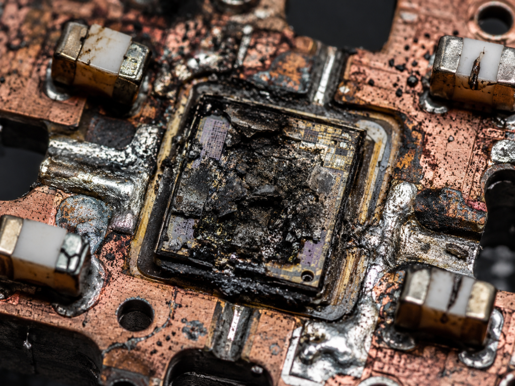
High-power RF transmitters require precision impedance matching. What’s the real story regarding these sudden thermal breakdowns? An active jamming system pushes massive current continuously. A disconnected load forces that energy nowhere useful. Voltage standing wave ratio spikes massively. This trapped RF energy converts directly into localized heat. Active device junctions exceed their maximum rated temperatures within milliseconds. Silicon laterally diffused metal oxide semiconductor transistors shatter. Gallium nitride high electron mobility transistors experience catastrophic gate degradation. Current consumption skyrockets beyond typical operational limits. Our datasheet specifically notes current consumption remains <= 20 A normally. However an infinite mismatch pulls massive uncontrolled amperage. Thermal resistance from device junctions toward copper baseplates degrades rapidly. Solder voids expand beneath active dies under extreme thermal cycling. Die attachment mechanisms fail completely under stress. Heat sinks become useless because thermal pathways sever entirely. You must implement robust protection circuitry immediately. . Without proper sensing loops, destruction occurs faster than software reacts. Hardware-level automatic level control loops save expensive final stage transistors. We build our modules expecting brutal operational mistakes. Thermal runaway melts aluminum housings during prolonged abuse. You must arrest power delivery within microseconds. Analog protection circuits outpace digital polling routines significantly. Your hardware base must possess inherent physical toughness.
Typical PA Performance Metrics
| Parameter | Min | Typ | Max | Units |
| Frequency Range | 30 | – | 512 | MHz |
| Output Power | 150 | 150 | – | W |
| Gain | 51 | 52 | 53 | dB |
3. Why do standard matching networks fail under high vibration?
Subtopic: Mechanical Integrity of RF Components
Commercial matching networks utilize brittle ceramic capacitors frequently. They snap under continuous vehicular chassis vibration. This is where it gets interesting regarding mechanical stress. Convoy jamming PA design demands extreme mechanical resilience. High-power matching requires large physical components handling intense voltages. These bulky components experience significant G-forces during off-road traversal. Solder joints crack over prolonged time periods. A cracked joint on a shunt capacitor detunes your entire network. This shifting impedance looks like a severed antenna. It causes internal reflection identical against external cable damage. We implement heavy-duty mechanical fixation for every critical RF component. The CRF-PA-30M512M-150W utilizes an optimized physical layout properly. Dimensions sit at 200 x 158 x 25 mm deliberately. This compact size minimizes PCB flexing under severe mechanical stress. We secure every heavy inductor using specialized epoxy compounds. Conformal coating prevents moisture ingress while adding solid structural rigidity. Our design ensures consistent performance across brutal outdoor terrain. You cannot fake ruggedness via simple software updates. True engineering truth lies within solid mechanical foundations. Broken ceramic components ruin excellent electrical designs. We eliminate these physical vulnerabilities during early prototype phases. You need hardware built like tank armor.
4. How does reflected energy backflow destroy output stages?
Subtopic: Voltage Breakdown and Transistor Death
Reflected power creates massive voltage peaks along transmission lines. These standing waves find weak points inside your output network. You might be wondering what physically breaks first inside. Drain-to-source breakdown voltage limits get exceeded instantaneously. Transistor dies physically burn creating microscopic craters. Sometimes isolation components fail before transistors melt completely. . Ferrite circulators crack under excessive reverse power heat. We engineer our CRF-PA-30M512M-150W handling massive high stress. It delivers a rated output power reaching 150 W. It operates continuously across a 30-512 MHz frequency range. Broad bandwidth means isolators cannot protect every specific frequency efficiently. Therefore we utilize highly robust GaN device architectures. GaN withstands significantly higher mismatch conditions compared against older technologies. It provides serious margin for unpredictable field emergencies. Our output VSWR specification remains <= 2.0:1 under normal loading. We design our circuitry surviving brief infinite mismatch events. This prevents total system failure during critical convoy movements. Proper design accounts for physics rather than perfect lab conditions. Engineers must understand transistor failure mechanisms deeply. We test bare dies pushing them past absolute limits. This data drives our final amplifier architecture.
Interface Specifications
| Port Type | Connector Reference |
| RF Input | SMA-Female |
| RF Output | N-Female |
| Control | DB9 |
| Output Power Type | CW/Saturated |
5. What role does VSWR tolerance play inside EW systems?
Subtopic: Dynamic Impedance and Continuous Operation
Electronic warfare applications demand continuous heavy transmission. A jammed spectrum prevents enemy communication reliably. But wait, there’s more regarding dynamic antenna loading. Antennas constantly detune near moving metallic vehicle structures. Moving turrets change local electromagnetic environments dynamically. This causes fluctuating impedance mismatches continuously during operation. Your convoy jamming PA design must tolerate these dynamic shifts. A brittle amplifier shuts down repeatedly under stress. Software resets leave convoys vulnerable for several seconds. We build amplifiers capable of operating through moderate mismatches seamlessly. The CRF-PA-30M512M-150W ensures incredibly stable amplification gain. Typical gain hits 52 dB across its operational band. Gain flatness stays tightly controlled at <= 1.8 dB. This consistency allows system integrators much needed breathing room. They lack complex dynamic matching network requirements. Our base hardware absorbs minor reflections seamlessly. It dissipates excess heat via its robust air cooling method. A reliable jammer never stops transmitting when things get messy. You want hardware fighting through intense physical adversity. We eliminate annoying false alarms triggering unwanted system reboots. Stable gain means predictable jamming coverage radiuses constantly.
6. How can engineers calculate link budgets for damaged antennas?
Subtopic: Graceful Degradation and Power Fold-Back
Calculating link budgets with damaged equipment seems counterintuitive. Yet combat engineering requires understanding degraded performance modes accurately. Now pay attention regarding these severe operational states. A sheared antenna might present an extreme 10:1 VSWR. Only a fraction of your 150 W reaches free space. Most transmitted energy bounces backward toward sensitive electronics. System designers must calculate effective radiated power under crippled states. Will a damaged system still jam nearby active threats? You must know your amplifier’s unique fold-back characteristics thoroughly. Many commercial units drop output completely during 3:1 VSWR events. Our architecture gracefully degrades power based strictly upon thermal limits. It keeps fighting while junction temperatures survive intact. The CRF-PA-30M512M-150W operates efficiently with an input drive near 0 dBm. You adjust drive levels based upon active feedback telemetry. Drop input drive slightly during severe reflection occurrences. This lowers overall thermal burden while maintaining a degraded jamming bubble. Link budgets must include these absolute worst-case scenarios. Never design solely expecting pristine laboratory equipment conditions. Combat destroys perfect hardware quickly. You must plan for fighting wounded. A weak jamming signal beats silence every single time.
Environmental Ratings
| Parameter | Min | Max | Units |
| Operating Temperature | -40 | +85 | °C |
| Storage Temperature | -40 | +85 | °C |
7. What makes the CRF-PA-30M512M-150W ideal for convoy applications?
Subtopic: Ruggedness and Military Compliance
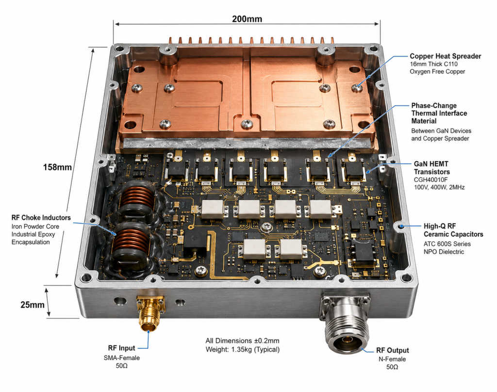
We designed this specific module addressing harsh battlefield realities. It requires a standard 28 VDC supply voltage strictly. Vehicles readily provide this reliable power bus architecture. Ready for the good part regarding its physical installation? It weighs merely <= 1.4 kg fully assembled. Integrators easily stack multiple modules inside tight equipment racks. Operating temperature spans from -40 °C up toward +85 °C safely. Extreme desert heat will not halt its continuous operation. Freezing high-altitude mountain passes pose zero operational threat. It utilizes a rugged SMA-Female RF input connector securely. An N-Female RF output connector handles massive continuous wave power. We provide comprehensive customization across various control interfaces. Our engineering team reviews feasibility requests within 48 hours. The unit complies strictly against ISO 9001 quality frameworks. It meets military GJB 9001C standards perfectly without compromise. We build serious RF muscle meant for harsh combat environments. Your convoy jamming PA design succeeds using proper foundation blocks. Choosing unverified hardware gambles human lives unnecessarily. We provide verified data guaranteeing peak performance under duress.
8. How does proper thermal dissipation prevent active component death?
Subtopic: Baseplate Interfaces and Thermodynamics
Heat acts as an ultimate enemy against semiconductor reliability. It silently destroys expensive transistors over prolonged time periods. Here’s the kicker about closed vehicle rack environments. Dense equipment racks restrict ambient airflow extremely severely. Our module relies heavily upon an integrated air cooling method. We machine our chassis directly from high-grade aerospace aluminum. Package size parameters at 200 x 158 x 25 mm maximize surface area heavily. Thermal paste alone fails under extreme high frequency vibration. We use advanced metallic phase change thermal interface materials. These maintain perfect contact between active dies and baseplates constantly. They withstand massive temperature swings without pumping out laterally. Storage temperature tolerances reach identical -40 °C toward +85 °C limits. A parked vehicle baking beneath direct sunlight remains fully functional. Active heat sinks require powerful external ventilation fans. Integrators must design shrouds directing air forcefully across our module. Poor system-level ventilation ruins excellent internal amplifier engineering. Always prioritize thermodynamics equally alongside advanced radio frequency engineering. Physics never forgives poor mechanical thermal management choices. Trapped heat melts solder joints rapidly. You must push thermal energy away from your active devices.
Mechanical Outline Characteristics
| Model | Dimensions | Weight |
| CRF-PA-30M512M-150W | 200 x 158 x 25 mm | <= 1.4 kg |
9. Why must R&D prioritize BOM selection against salt fog?
Subtopic: Corrosion Resistance and Material Science
Coastal operations introduce horrific rapid hardware corrosion problems. Salt fog destroys unprotected copper traces within mere weeks. Truth be told about many modern RF design engineers. Many ignore critical environmental sealing entirely during initial prototyping. They test systems inside air-conditioned laboratories almost exclusively. Field deployments reveal their massive oversight extremely quickly. A corroded ground plane shifts internal impedances totally unpredictably. This creates high VSWR internally before power reaches antennas. We build our CRF-PA-30M512M-150W using specialized anti-corrosion plating. . All internal components receive protective waterproof conformal barriers. We select hardware passing strict RoHS compliance checks. Non-compliant cheap fasteners cause galvanic corrosion against aluminum chassis. We eliminate mixed-metal contacts preventing this battery-like decay. RF output connectors receive specialized marine weatherproofing treatments. Moisture ingress via an N-Female connector ruins output networks instantly. Your entire convoy jamming PA design fails because of moisture. Pay extreme attention toward microscopic hardware details. Nature exploits every single physical shortcut you take. Saltwater acts as a highly conductive destructive force. We block environmental threats physically at every mechanical boundary.
10. How do integrators verify robust convoy jamming PA design?
Subtopic: Dynamic Testing and Validation
You cannot verify survivability using simple scalar network analyzers. Real testing requires dynamic stress under full operational power. Let me show you a proper ruggedness validation procedure. Connect your amplifier directly toward a high-power mismatch load. Sweep frequency range parameters from 30-512 MHz continuously. Monitor your spectrum analyzer for abnormal unstable spurious emissions. Our module guarantees spurious outputs remain <= -60 dBc. Harmonics stay suppressed firmly at <= -10 dBc levels. If your amplifier breaks into wild oscillation, you fail. Measure reverse power handling capability manually during active transmission. Intentionally disconnect your output for brief millisecond intervals. Verify protection circuits engage before catastrophic transistor failure happens. Analyze input VSWR remaining <= 1.8:1 during heavy operation. Ensure it matches your primary system exciter correctly. We provide MTBF reliability data upon request for project reviews. Stop guessing about hardware performance limits. Test your hardware until it bleeds physically. Only then can you trust it protecting human lives. Engineering demands empirical proof.
Compliance Framework
| Certification | Status |
| RoHS | Compliant |
| CE / FCC | Compliant |
| ISO 9001 | Certified |
| GJB 9001C | Certified |
We have examined critical engineering aspects concerning severe mismatch conditions. You must prioritize thermal dissipation alongside robust matching networks. Selecting proper components like our CRF-PA-30M512M-150W ensures absolute battlefield survivability. Reach out immediately for full datasheet access regarding system integration. Never compromise your engineering truth when lives remain at stake.
FAQ Section
Q1: What drives convoy jamming PA design failures?
Antenna damage causes massive reflected energy spikes. This destroys output transistors instantly.
Q2: How do antenna open circuits trigger thermal runaway?
Reflected power turns into localized heat. Active device junctions exceed thermal limits.
Q3: Why do standard matching networks fail under high vibration?
Brittle ceramic components snap. This creates internal impedance mismatches mimicking external cable breaks.
Q4: How does reflected energy backflow destroy output stages?
Voltage peaks exceed breakdown limits. Transistor dies physically burn creating microscopic craters.
Q5: What makes the CRF-PA-30M512M-150W ideal for convoy applications?
It uses robust GaN architecture. It withstands infinite mismatches briefly without catastrophic failure.
Authorized RF engineering and compliance review
For regulated RF systems, this page should be used as an engineering and compliance review path, not as a public deployment checklist. CorelixRF starts with authorization status, operating region, frequency plan, output limit, antenna interface, safety controls, thermal limits and acceptance documents.
- RFQ checklist – send the data buyers usually forget, including band, power, duty cycle, interface and test standard
- delivery documentation – check what documents can support incoming inspection, FAT review and long-term maintenance
- quality and certification review – review the quality and compliance evidence before the project moves into procurement
- RF front-end platform – compare the RF chain as a system instead of selecting one isolated module
- RF configurator – turn frequency, power, thermal and interface requirements into a first configuration brief
- case studies – review similar engineering paths before sending an RFQ
- engineering contact – send the application notes, block diagram or target specification to engineering sales
This keeps the discussion inside lawful, authorized RF programs while still giving procurement teams a clear way to request amplifier, antenna, SDR source, documentation and factory review.