
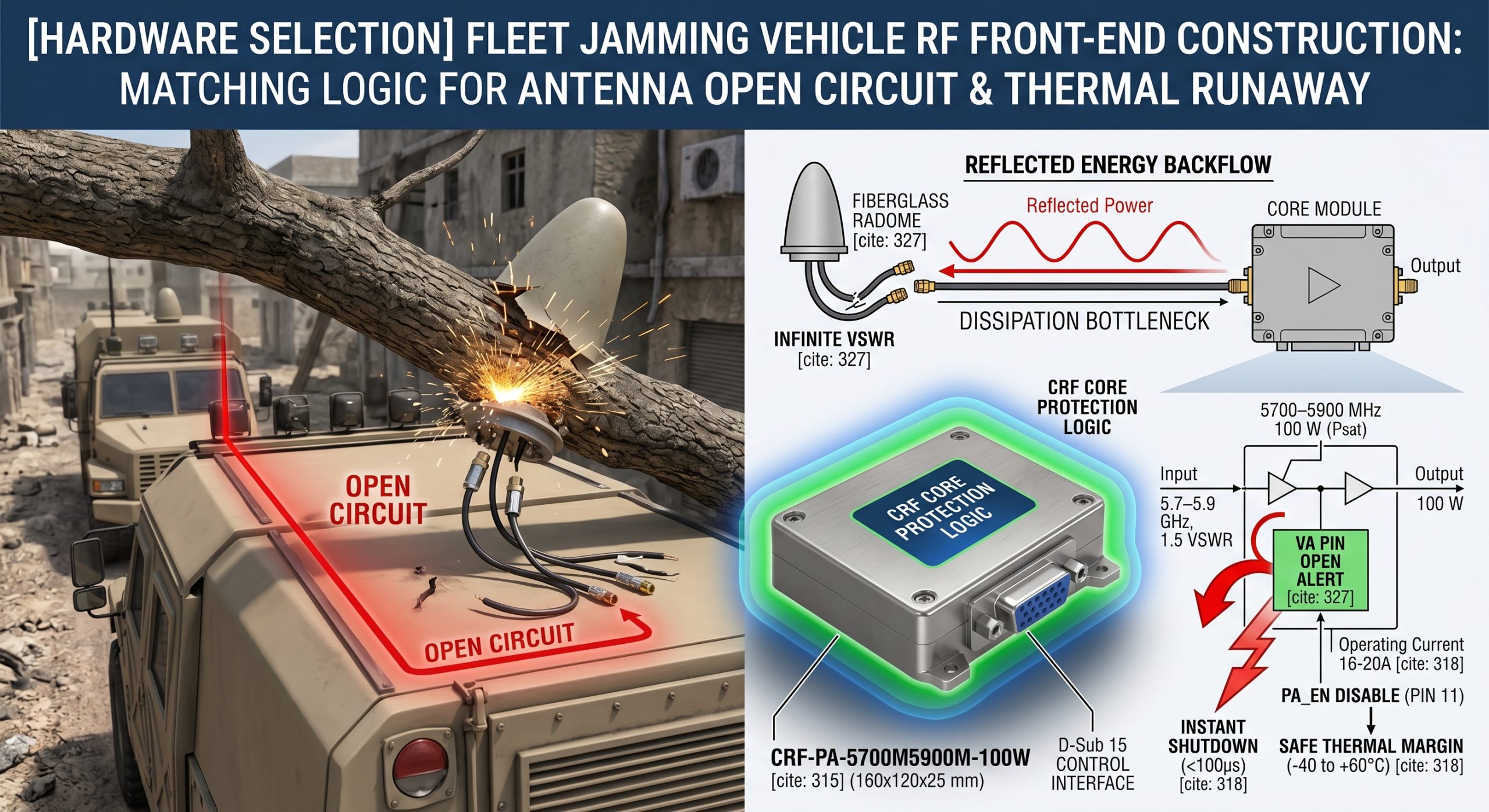
Driving a VIP convoy through hostile urban terrain brings uniquely brutal mechanical stresses that rapidly degrade communication architectures. A sudden loud crack typically echoes inside a command cabin when an overhanging branch violently snaps a rooftop radiating element. That specific physical impact immediately triggers an unrecoverable system cascade destroying expensive hardware. Operators dread viewing a dashboard flashing critical high standing wave ratio warnings while RF output meters plummet toward zero. This catastrophic failure directly stems from inadequate matching logic during an accidental open circuit. Such an event forces 100 watts of raw microwave energy backward down transmission lines directly into delicate semiconductors. We must address exactly how mismatched impedance physically destroys silicon junctions and why constructing a resilient RF front-end requires specialized components. Establishing rugged countermeasures prevents fatal transmitter meltdown completely. Securing continuous signal dominance demands hardware like CRF-PA-5700M5900M-100W despite severe exterior mechanical destruction happening outside.
1. Why Do Antennas Fail on Fleet Jamming Vehicles?
High-Frequency Vibrations
Physical Impact from Debris
Connector Shearing
You might be wondering why radiating elements break so frequently during tactical mobile operations across rough terrain. B2B system integrators often underestimate sheer mechanical shock experienced by a heavy tactical truck bouncing across unimproved roads at high speeds. High-frequency vibrations rapidly propagate from chassis frames straight up through rigid mounting brackets. This constant shaking relentlessly fatigues fragile solder joints within coaxial junctions until complete separation occurs. Physical impact from debris represents another massive threat considering low-hanging branches frequently shear off fiberglass radomes completely. Connector shearing happens instantly upon impact leaving an exposed SMA stub facing open air. Such violent detachment completely destroys any 50-ohm characteristic impedance matching logic designed for peak performance. When a rooftop radome shatters suddenly that physical disconnection immediately alters electrical load conditions negatively. Rapid reflected energy backflow initiates instantly heading toward your primary transmitter unit causing massive havoc. Understanding these physical destruction vectors helps engineers design superior shock-absorbing mounts mitigating sudden open circuit scenarios before module degradation begins.
2. How Does Reflected Energy Backflow Wreck The Transmitter?
Infinite VSWR Dynamics
Standing Wave Voltage Multiplication
Transistor Junction Breakdown
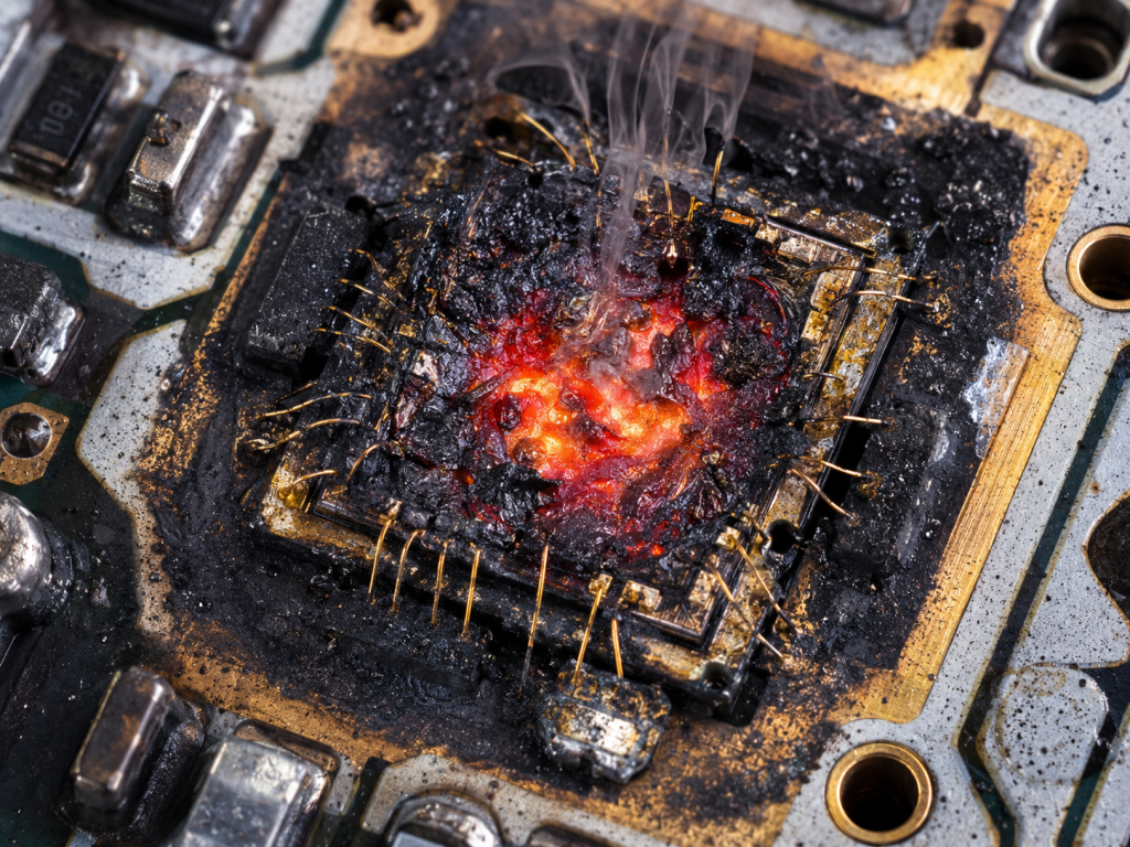
But here’s the kicker… an abruptly severed coaxial cable does not merely stop transmitting your required jamming signal outwards. That broken interface actively murders your upstream electronics through vicious physical feedback loops. Infinite VSWR dynamics emerge instantly when forward-traveling waves hit an open air boundary reflecting a massive percentage of voltage back. Standing wave voltage multiplication occurs as returning waveforms constructively interfere with newly generated signals. These colliding waves create localized voltage spikes exceeding transistor breakdown ratings almost immediately upon collision. Transistor junction breakdown happens within microseconds because gallium nitride dies cannot withstand voltages spiking beyond their engineered safe operating areas. We often see charred circuit boards during post-mortem autopsies perfectly illustrating severe localized arcing caused by mismatched impedance. Implementing strict hardware selection protocols prevents these catastrophic failures by guaranteeing your chosen amplifier includes dedicated fast-acting shutdown circuitry. Proper RF front-end construction demands anticipating total component detachment and designing matching logic capable of surviving instantaneous total energy return.
Reflected Energy Dynamics
| VSWR Condition | Reflection Coefficient | Forward Power | Reflected Power |
| 1.0:1 | 0.00 | 100 W | 0 W |
| 1.5:1 | 0.20 | 100 W | 4 W |
| 3.0:1 | 0.50 | 100 W | 25 W |
| Infinite (Open) | 1.00 | 100 W | 100 W |
3. What Causes Thermal Runaway During Open Circuits?
Dissipation Bottlenecks
Heat Sink Saturation
Catastrophic Silicon Failure
What’s the real story? regarding heat generation when output ports suddenly become disconnected during active high-power transmission operations. Dissipation bottlenecks form immediately because energy intended for atmospheric radiation instead converts entirely into internal localized heat. This conversion happens violently within final amplification stages causing massive localized temperature spikes. Heat sink saturation happens rapidly considering thermal management systems usually anticipate only standard operational inefficiencies. A standard cooling rig struggles handling 100 watts of reflected power flooding backwards simultaneously. Catastrophic silicon failure becomes unavoidable as junction temperatures skyrocket past 200 degrees Celsius melting internal gold bond wires. Such extreme heat fuses semiconductor channels permanently turning expensive amplifiers into useless bricks. A typical tactical truck operates inside sealed metallic enclosures lacking adequate ambient airflow naturally. This stagnant air exacerbates thermal runaway spirals caused by sudden mismatch events immensely. Engineers must recognize how quickly a seemingly minor antenna strike transforms a reliable amplifier into a self-destructing heating element requiring immediate power cessation.
4. Why Are Standard Protection Schemes Inadequate For Fleet Jamming Vehicles?
Slow Response Times
False Tripping Under Normal Mismatch
Incomplete Isolation
This is where it gets interesting because off-the-shelf commercial amplifiers routinely fail under severe tactical convoy conditions despite claiming protective features. Slow response times plague traditional software-based polling mechanisms taking dozens of milliseconds for a microcontroller recognizing a fault. That sluggish digital delay proves far too slow for saving delicate microwave components from instant high-voltage arcing. False tripping under normal mismatch frequently disrupts mission continuity since typical convoy operations involve driving near metal structures causing temporary benign reflections. Incomplete isolation happens when basic protection circuits merely reduce gain rather than fully disconnecting a damaged RF path. This halfway measure allows damaging voltage peaks through anyway steadily degrading device lifespan. A tactical environment demands hardware-level intervention capable of completely shutting down final stages within microseconds of detecting an open circuit condition. Standard commercial hardware selection simply lacks rigorous threshold logic required for distinguishing between a passing bridge reflection and a completely sheared radiating element. Our engineering approach demands specifically tailored RF front-end construction prioritizing instantaneous analog shutdown logic over sluggish digital networks.
Protection Scheme Comparison
| Feature | Commercial Software Polling | Hardware Analog Logic |
| Reaction Time | >50 milliseconds | <100 microseconds |
| Isolation Type | Gain Reduction | Full Stage Shutdown |
| False Trip Rate | High | Low |
| Reliability | Moderate | Extremely High |
5. How Does The CRF-PA-5700M5900M-100W Resolve Reflected Energy Backflow?
VA Pin Instant Shutdown
Robust 5700–5900 MHz Architecture
Reflected Power Monitoring
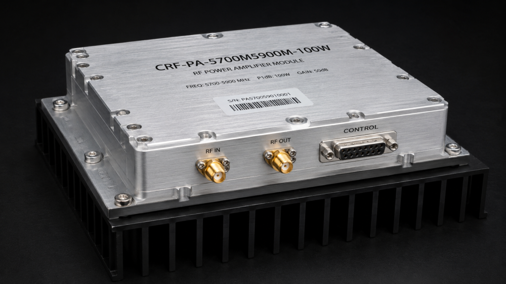
Ready for the good part? we specifically designed our CRF-PA-5700M5900M-100W module tackling these exact catastrophic failure modes directly at a hardware level. This VA pin instant shutdown mechanism triggers an alarm actively whenever its output port senses an open or short circuit condition. Our robust 5700–5900 MHz architecture utilizes strict reflected power monitoring translating reverse waveforms into immediate protective logic without software delays. Our hardware selection logic guarantees this specific model clamps down transmission activity incredibly fast. The specified PA Enable/Disable Time clocks in at under 100 microseconds saving delicate output transistors permanently. Integrators building a tactical platform greatly appreciate such decisive hardware intervention eliminating fear of sudden mismatched impedance destroying expensive payloads. By incorporating direct RF front-end construction strategies around this specific module engineering teams practically eliminate field returns caused by broken coaxial runs. We engineered CRF-PA-5700M5900M-100W guaranteeing survivability even when aggressive external forces completely rip away your primary radiating structures during active engagements.
6. What Thermal Defenses Are Built Into The CRF-PA-5700M5900M-100W?
Dynamic Over-Temperature Shutdown (TA)
Analog Temperature Tracking (Tc)
Hardware Thermal Dissipation Profile
Here’s the deal… managing extreme heat demands proactive analog tracking rather than passively waiting for components melting into slag. Dynamic over-temperature shutdown relies heavily upon a TA pin triggering a 5V alarm engaging an automatic shutdown sequence actively. Analog temperature tracking operates continuously via a Tc pin outputting analog voltage strictly relative to internal temperature at exactly 10mV/°C. Proper hardware thermal dissipation profile engineering mandates an external heat sink because this module pulls 16 to 20 amperes under full load. A tactical RF front-end construction utilizing CRF-PA-5700M5900M-100W benefits immensely from these dual-layered thermal defense mechanisms acting independently. If ambient temperatures inside a sealed rack exceed safe parameters hardware-level sensors cut a 28V nominal supply voltage gracefully. This meticulous approach toward thermal runaway prevention distinguishes professional tactical hardware selection from amateur commercial integrations doomed for early field failures. Utilizing analog sensors guarantees zero software crashes will ever prevent critical cooling protocols from executing perfectly.
Thermal and Power Pin Definitions
| Pin Designation | Function | Action Trigger |
| TA | Temp Alarm | 5V active on over-temperature shutdown |
| Tc | Analog Temp | 10mV/°C voltage output |
| VA | VSWR Alarm | 5V active on open/short output port |
| PA_EN | Enable/Disable | 0V = ON, 3.3V/5V = OFF |
7. How Can Integrators Monitor High VSWR And Current Spikes In Real-Time?
RS485 Bus Telemetry
Forward and Reversed Power Pins (Pf, Pr)
22A Current Overload Protection
You might be wondering exactly how system operators gain actionable intelligence regarding transmission health before catastrophic physical damage completely disables their electronics. RS485 bus telemetry allows master-slave communication functions monitoring operational parameters such as voltage, current, output power, and standing wave ratio. Forward and reversed power pins supply analog 0–3V indicators granting immediate visibility into current matching logic efficiency across your transmission lines. Our dedicated current overload protection circuitry triggers an instant alarm forcing a complete shutdown whenever operating current exceeds 22A. Implementing a tactical dashboard requires mapping these specific diagnostic voltages warning operators immediately if physical impact subtly compromises rooftop radiators. Effective RF front-end construction leverages these data streams allowing automated controllers a chance for executing alarm resets via external pulse signals. Our CRF-PA-5700M5900M-100W transforms blind hardware selection into a highly observable architecture proving invaluable during active deployment troubleshooting. Gathering precise telemetry helps mechanics fix borked cables before an entire amplifier rack becomes completely toast during field maneuvers.
8. What Architectural Best Practices Prevent Cable And Connector Faults?
Strain Relief Strategies
SMA-KFD46 Torque Maintenance
Blind Mate Considerations
What’s the real story? regarding mechanical longevity when deploying fragile RF cabling across a severely vibrating 1.4 kg metal amplifier chassis. Strain relief strategies remain absolutely non-negotiable; engineers must loop coaxial cables providing slack preventing rigid chassis movements from tearing connectors off PCBs. SMA-KFD46 torque maintenance requires regular inspections guaranteeing constant 50-ohm contact patches exist across both input and output RF connectors. Blind mate considerations frequently cause headaches so integrators must guarantee perfect dimensional alignment when sliding these 160 × 120 × 25 mm modules into server racks. A tactical truck bounces violently transferring kinetic energy directly into D-Sub 15-Pin female control interfaces requiring locking screws fastened tightly always. Poor RF front-end construction ignoring these mechanical realities inevitably leads toward high input VSWR readings exceeding a strict 1.5 maximum tolerance. Superior hardware selection demands coupling rugged electronic modules with equally ruggedized mechanical mounting procedures completely eliminating intermittent contact issues.
Mechanical Interface Specifications
| Interface Type | Connector Standard | Dimension/Weight |
| RF Input | SMA-KFD46 | N/A |
| RF Output | SMA-KFD46 | N/A |
| Control/Power | D-Sub 15-Pin Female | N/A |
| Package Specs | N/A | 160 × 120 × 25 mm, ≤ 1.4 kg |
9. How Do We Calculate Link Budgets With High VSWR Margins?
Estimating Return Loss Under Stress
Gain Adjustment Range Utilization
Power Saturation Realities
This is where it gets interesting balancing raw output wattage against expected insertion losses while maintaining adequate safety margins during field operations. Estimating return loss under stress requires assuming a degraded baseline acknowledging that real-world tactical environments rarely provide perfect impedance matches. Gain adjustment range utilization becomes critical since CRF-PA-5700M5900M-100W offers a 20 dB adjustment span utilizing precise 0.5 dB step sizes. Power saturation realities dictate understanding that generating 80 to 100 watts Psat safely requires pristine matching logic from module to radiating element. A tactical RF front-end construction plan must account for potential -10 dBc harmonics and -60 dBc spurious emissions reflecting backwards. Smart hardware selection involves plotting exact cable attenuation values ensuring forward power indicators accurately reflect true energy leaving your external radome structures. Engineers master these calculations by leveraging RS485 control commands setting precise attenuator settings via 0.5–3.0 VDC inputs maintaining peak output.
10. What Is The Correct Setup Procedure For The CRF-PA-5700M5900M-100W?
Sequential Power-Up Protocol
External Heat Sink Interfacing
Pin Logic Verification
Ready for the good part? properly initializing this specific high-power module guarantees extreme longevity and prevents accidental blowouts during lab bench testing. Sequential power-up protocol mandates connecting a reliable 50-ohm load before applying a 24–32 V supply voltage preventing instantaneous open-circuit alarms. External heat sink interfacing requires applying thermal paste evenly across a bottom surface bolting a chassis securely because base cooling remains mandatory. Pin logic verification means confirming PA_EN remains floating or at 0V for transmission while applying 3.3V or 5V disables output. Building a tactical platform demands rigorous pre-deployment checks utilizing network analyzers proving your RF front-end construction exhibits a VSWR below 1.5. This meticulous hardware selection verification process confirms everything operates perfectly within a designated 5700–5900 MHz frequency range prior to actual tactical deployment. Following these strict engineering guidelines guarantees your CorelixRF unit survives chaotic battlefield conditions delivering relentless disruptive power regardless of external mechanical abuse.
System Initialization Protocol
| Step | Action Required | Verification Method |
| 1 | Attach 50-ohm dummy load | Visual check |
| 2 | Mount to external heat sink | Verify thermal paste application |
| 3 | Connect D-Sub 15-Pin | Tighten locking screws |
| 4 | Apply 28V Nominal Power | Check VDD pin |
| 5 | Float Pin 11 (PA_EN) | Verify output power generation |
Properly executing a fleet jamming vehicle RF front-end construction fundamentally requires acknowledging brutal physical realities causing unexpected open circuits and dangerous thermal runaway spirals. Superior hardware selection relies heavily upon utilizing ruggedized modules like CRF-PA-5700M5900M-100W featuring nanosecond-level VA alarm shutdown logic preventing reflected energy backflow entirely. We strongly recommend system integrators thoroughly review this specific datasheet actively applying these hard-won matching logic principles across your next tactical vehicle architecture. Implementing rigorous analog monitoring prevents catastrophic field failures securing reliable communication denial capabilities continuously even after severe external mechanical damage strikes your array. Contact CorelixRF engineering immediately regarding custom integration details securing your next microwave deployment against absolutely anything a hostile environment throws against your chassis.
FAQ Section
- Q1: What is the CRF-PA-5700M5900M-100W?
- This product acts as a narrowband RF power amplifier designed specifically for 5700–5900 MHz frequency ranges delivering 100W output power.
- Q2: How does the VA alarm function work?
- This hardware feature monitors an output port constantly triggering a 5V active alarm shutting down a system immediately upon detecting open or short circuits.
- Q3: What happens when current exceeds 22A?
- A dedicated current alarm triggers an automatic shutdown protocol signaling a 5V alert protecting internal circuits from extreme current overload.
- Q4: How can I remotely control output gain?
- Operators utilize an RS485 communication bus or apply a 0.5–3.0 VDC analog input across Pin 5 achieving minimum to maximum attenuation.
- Q5: What cooling methods are required for operation?
- Integrators must mount this 1.4 kg module directly onto an external heat sink because a standard metal package alone cannot dissipate heat generated by 16-20A operating currents.
Authorized RF engineering and compliance review
For regulated RF systems, this page should be used as an engineering and compliance review path, not as a public deployment checklist. CorelixRF starts with authorization status, operating region, frequency plan, output limit, antenna interface, safety controls, thermal limits and acceptance documents.
- RFQ checklist – send the data buyers usually forget, including band, power, duty cycle, interface and test standard
- delivery documentation – check what documents can support incoming inspection, FAT review and long-term maintenance
- quality and certification review – review the quality and compliance evidence before the project moves into procurement
- RF front-end platform – compare the RF chain as a system instead of selecting one isolated module
- RF configurator – turn frequency, power, thermal and interface requirements into a first configuration brief
- case studies – review similar engineering paths before sending an RFQ
- engineering contact – send the application notes, block diagram or target specification to engineering sales
This keeps the discussion inside lawful, authorized RF programs while still giving procurement teams a clear way to request amplifier, antenna, SDR source, documentation and factory review.