
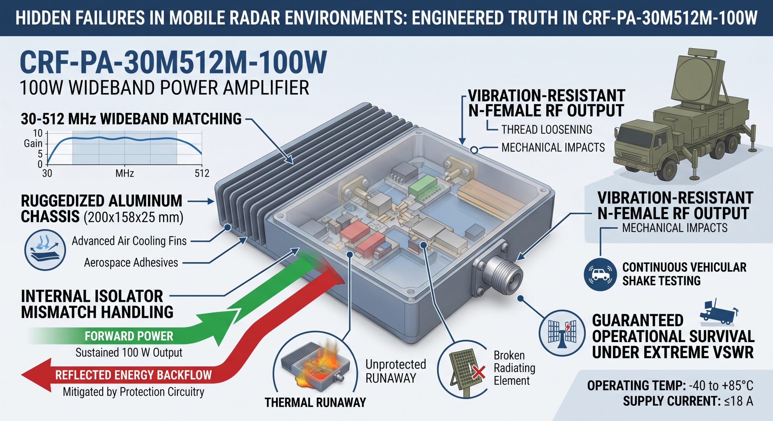
Mobile tactical radar systems face brutal operational realities daily. Operators often report sudden power drops during rough off-road terrain transits. A tactical screen flashes a high Voltage Standing Wave Ratio fault immediately. Seconds later, your entire transmission chain goes permanently dark. Such unexpected hardware failures paralyze mission-critical tracking capabilities. Standard commercial amplifiers melt when severed coaxial cables bounce raw RF power back. Returning energy destroys sensitive output stages instantly. We present a proven engineering method bypassing this catastrophic fault entirely. CorelixRF hardware features internal isolators and ruggedized mismatch handling. You get sustained 100 W output without sudden burnout. We rely strictly on verified physical principles. Here’s the deal. Our CRF-PA-30M512M-100W module withstands extreme abuse continuously. We designed this unit specifically for harsh vehicular platforms. Your radar array maintains tracking lock despite broken radiating elements. We engineer truth into every single milled aluminum chassis. We guarantee operational survival under worst-case VSWR conditions.
1 What Are The Symptoms Of Antenna Damage In Mobile Radar Systems?
Recognizing Field Failures
Continuous terrain impacts physically alter heavy mast-mounted arrays over time. Severe shaking gradually loosens primary N-type mechanical linkages constantly. An operator might notice target acquisition ranges dropping sporadically during patrols. These intermittent blind spots indicate severe transmission line degradation visually. Reflected energy backflow begins accumulating inside your final amplification stage. You check built-in diagnostic panels immediately for voltage anomalies. System logs show erratic current consumption spikes above normal operating limits. These current spikes happen because forward power bounces off a damaged radiating element. Energy has nowhere else left inside that closed transmission loop. Forward signals return violently down that same coaxial path. We observe this exact phenomenon during aggressive vehicle shake testing. An unexpected open circuit instantly alters system impedance from 50 ohms. Reverse power hits internal drain contacts directly. Unprotected circuitry self-destructs within fractions of a second. What’s the real story? Most integrators blame cheap cables instead of fundamental matching network flaws. We know true failure originates from poor RF architecture design.
2 How Does High-Frequency Vibration Compromise RF Interfaces?
Physics of Tactical Connectors
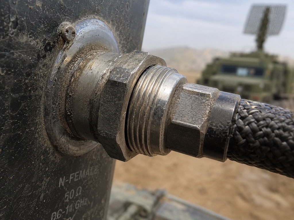
Tactical vehicles generate immense mechanical stress across bare chassis mounting points. Sustained low-frequency rumble causes threaded locking nuts on RF cables slowly back out. A loosened RF OUT N-Female connector immediately breaks perfect electrical contact. Even a microscopic air gap shifts phase angles drastically during transmission. Your perfectly matched load vanishes into thin air instantly. Impedance mismatch creates massive standing waves along main transmission lines. Reflected energy backflow magnifies voltage nodes at vulnerable transistor junctions. Typical commercial off-the-shelf units lack adequate shock mounting completely. CorelixRF utilizes thirty years of manufacturing experience solving these dynamic faults. We machine rigid aluminum housings measuring $200\times158\times25~mm$ exactly. Our factory employs 400 skilled technicians assembling robust military-grade enclosures. Solid mechanical foundations prevent interface degradation completely during deployment. Heavy shock loads cannot twist our proprietary internal circuit boards. We anchor every critical component down using specialized aerospace adhesives. This is where it gets interesting. True reliability requires absolute mastery over mechanical engineering principles.
Mobile Radar Vibration Impacts
| Interface Component | Failure Mode | Electrical Consequence |
| N-Female Connector | Thread Loosening | Complete Open Circuit |
| SMA-Female Input | Solder Stress | Input VSWR Spikes |
| Antenna Element | Snap Fracture | Total Impedance Mismatch |
| DB9 Control Port | Pin Bending | Telemetry Loss |
3 How Do Open Circuits Cause Reflected Energy Backflow?
Understanding Standing Waves
An intact antenna provides a perfect fifty-ohm termination sink always. Radio frequency energy flows outward seamlessly into open tactical space. A severed cable instantly creates infinite impedance at that specific break point. You might be wondering. Where does all that generated power actually go? Raw power reverses direction immediately upon hitting that dead end. Forward waves collide violently against returning reverse waves inside your cable. This collision forms stationary high-voltage peaks known as standing waves. Reflected energy backflow travels backward into your amplifier output stage. The CRF-PA-30M512M-100W handles these brutal reflections through specialized internal circuitry. Our engineering team designed rugged RF paths specifically for this combat scenario. We prevent disastrous energy accumulation near fragile silicon dies completely. You maintain operational readiness despite broken physical transmission lines. We build amplifiers utilizing pure engineering truth without compromise. High return loss equals catastrophic hardware death without proper mitigation. Our designs absorb that returning shockwave gracefully every single time.
4 Why Does Reflected Power Lead To Immediate Thermal Runaway?
Thermodynamics of Device Failure
Transistors operating at microwave frequencies generate significant internal heat naturally. A perfectly matched system dissipates thermal loads efficiently through flat baseplates. Reflected energy backflow completely disrupts this delicate thermal equilibrium. Returning power forces transistors outside their safe operating areas rapidly. Die temperatures skyrocket within microseconds of a cable fault. This localized heating causes current draw increases rapidly across active channels. Higher currents generate even more heat simultaneously inside microscopic junction areas. Thermal runaway melts semiconductor junctions permanently without active protection. Standard amplifiers become dead weight on your radar mast quickly. CorelixRF equipment requires maximum current consumption of $\le18$ A only. Our conservative current limits prevent catastrophic semiconductor meltdown. But here’s the kicker. We utilize specialized air cooling methods for maximum heat extraction. Advanced chassis fins channel ambient airflow across critical hot spots efficiently. We stop thermal runaway cold before permanent degradation occurs.
Thermal Runaway Progression Timeline
| Time Elapsed | Physical Event | Amplifier Status |
| 1 Microsecond | Antenna Cable Snaps | Output VSWR Spikes |
| 10 Microseconds | Reflected Energy Backflow Hits | Voltage Nodes Multiply |
| 1 Millisecond | Junction Temperature Spikes | Current Draw Accelerates |
| 10 Milliseconds | Thermal Runaway Ignites | Unrecoverable Damage |
5 How Can Engineers Diagnose VSWR Spikes In The Field?
Frontline Testing Procedures
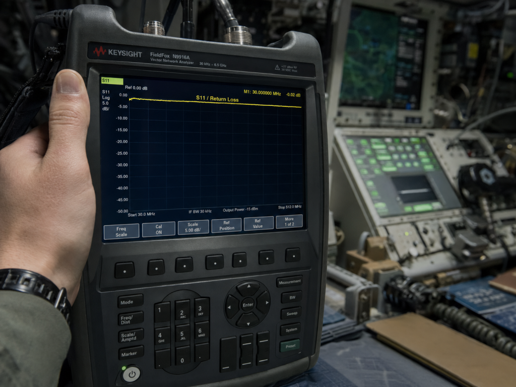
Field technicians must identify hidden faults before swapping expensive components blindly. An inline directional wattmeter provides immediate forward and reverse power readings. High reverse power confirms massive downstream impedance mismatches instantly. You disconnect suspect cables from your main transmission source immediately. Connect a portable Vector Network Analyzer directly onto those suspect lines. Sweep suspect lines across 30-512 MHz frequencies verifying integrity. Look closely at S11 return loss traces on your instrument screen. A flatlined trace near zero decibels indicates a total open circuit. We see these signatures frequently during demanding tactical deployments. The CRF-PA-30M512M-100W tolerates output VSWR up to $\le2.0$:1 safely. Diagnostics must isolate physical breaks accurately utilizing precise laboratory equipment. Ready for the good part? You can verify amplifier health independent of radiating elements. Inject a continuous wave signal checking flat gain responses. Proper troubleshooting saves thousands of dollars in ruined replacement parts.
6 What Oscilloscope Signatures Reveal Amplifier Stress?
Analyzing Time-Domain Waveforms
An oscilloscope captures rapid voltage transients invisible on standard power meters. Probing an amplifier bias line reveals deep operational secrets instantly. Normal operation shows stable direct current voltage with minimal ripple. Reflected energy backflow induces severe high-frequency oscillations onto sensitive supply lines. These parasitic oscillations force active devices into chaotic nonlinear operating regions. A sharp downward dip in drain voltage indicates massive electrical stress. You will observe harsh clipping on RF output envelopes clearly. We use fast oscilloscopes during exhaustive factory burn-in testing. Our engineers ensure 28 VDC supply lines remain rock solid. What’s the catch? Cheap power supplies collapse under rapid dynamic load changes. We filter our power rails utilizing massive capacitor banks. You avoid chaotic signal distortion during critical radar sweeps completely. Your spectrum remains clean despite harsh operating conditions outside. We monitor every nanosecond of performance before shipping anything.
Diagnostic Equipment Signatures
| Test Equipment | Normal Operation | Open Circuit Fault |
| Directional Wattmeter | Zero Reverse Power | Massive Reflected Power |
| Vector Network Analyzer | Sharp S11 Resonance | Flat S11 Near 0 dB |
| Fast Oscilloscope | Stable DC Bias | Severe Supply Ripple |
| RF Spectrum Analyzer | Clean Main Carrier | Broadband Noise Floor |
7 How Does The CRF-PA-30M512M-100W Survive Open Circuits?
CorelixRF Hardware Resilience
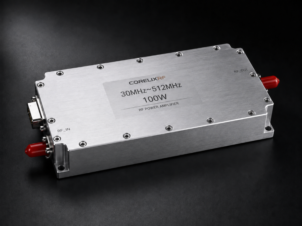
Our factory focuses entirely on robust RF power solutions daily. We designed the CRF-PA-30M512M-100W specifically for brutal tactical environments. This wideband unit delivers 100 W CW or saturated power. We employ advanced ruggedized transistors internally handling massive voltage swings. These specific devices feature exceptionally high breakdown voltages intrinsically. They withstand extreme voltage standing waves without instantaneous self-destruction. Reflected energy backflow encounters heavy-duty output matching networks immediately. These networks dissipate returning power away from sensitive active channels. We limit storage temperature between -40 and +85°C safely. Operating temperature mirrors these same rugged environmental limits perfectly. Here’s the deal. Our hardware survives when competing units fail miserably. We test every module against dead shorts before factory boxing. You receive battlefield-ready equipment requiring zero pampering during deployment. Engineering truth means delivering promised specifications under extreme duress.
Table 4: CorelixRF Amplifier Specifications
| Critical Parameter | Specified Value | Field Benefit |
| Frequency Range | 30-512 MHz | Covers entire tactical band |
| Output Power | 100 W | Long range radar punch |
| Gain Flatness | $\le1.8$ dB | Consistent pulse shapes |
| Supply Voltage | 28 VDC | Standard vehicle power |
8 What Specific Design Choices Handle 100W Reflected Power?
Internal Protective Mechanisms
A bare transistor cannot survive pure raw returning energy alone. Engineers must integrate physical hardware safeguards into every circuit board. We utilize high-power directional couplers monitoring forward transmission levels constantly. These identical couplers also measure reflected energy backflow accurately. An analog control loop throttles input drive instantaneously during fault conditions. This rapid attenuation protects delicate final stage amplification blocks entirely. This is where it gets interesting. The unit operates efficiently within a package size of $200\times158\times25~mm$. We keep total weight under $\le1.4$ kg for drone compatibility. Air cooling methods dissipate residual heat from mismatched loads effectively. Physical design dictates ultimate survival regarding tactical microwave assemblies. We isolate RF sections utilizing heavily shielded aluminum compartments. This shielding prevents parasitic feedback loops ruining clean signal amplification. Your system stays alive longer using our proprietary architecture.
9 How Does The 30-512 MHz Wideband Design Mitigate Tuning Drifts?
Broadband Matching Advantages
Narrowband amplifiers suffer terribly when antenna physical characteristics alter slightly. A bent radiating element shifts resonant frequencies away from center instantly. This shift creates localized mismatches leading toward immense component stress. How does wideband architecture solve this dangerous drift problem? The CRF-PA-30M512M-100W maintains consistent 50 dB typical gain. Our broadband matching networks absorb slight impedance variations naturally. Reflected energy backflow remains minimal across slight detuning events. We guarantee input VSWR stays strictly $\le1.8$:1 under full drive. You might be wondering. Why don’t all manufacturers use wideband matching exclusively? Designing flat broadband networks requires immense mathematical and practical expertise. We achieved less than 1.8 dB gain flatness across huge spans. Your radar system maintains continuous tracking regardless of minor damages. We engineer truth into every single manufactured trace systematically.
10 What Are The Ultimate System Integration Guidelines For Mobile Radars?
Final Installation Protocols
Proper installation prevents ninety percent of all field equipment failures. Technicians must torque every SMA-Female RF input connector precisely. You secure all DB9 control cables against heavy chassis vibrations. Sloppy cable routing guarantees future open circuits during combat maneuvers. Operators should monitor current draw via system telemetry continually. Any sudden drop signifies an immediate downstream RF pathway rupture. You swap damaged antennas before reapplying full transmission power. CorelixRF provides custom frequency bands or control interfaces quickly. Our engineering team reviews feasibility requests within 48 hours. Follow absolute engineering fundamentals always without cutting ridiculous corners. What’s the real story? Sloppy integration destroys perfectly good amplifiers daily. We provide mounting hole patterns sized 110.4 mm and 158 mm clearly. Use correct hardware securing modules onto massive thermal sinks.
Field Integration Checklist
| Integration Task | Tool Required | Verification Method |
| RF Out Connector | Torque Wrench | Visual Thread Check |
| Coaxial Routing | Tie Wraps | Vibration Shake Test |
| Baseplate Mount | Thermal Compound | Heat Sink Adhesion |
| System Power Up | Ammeter | Current $\le18$ A |
Conclusion
Mobile radar systems demand uncompromising hardware resilience against severe physical trauma. Unexpected antenna damage triggers massive reflected energy backflow rapidly. You prevent thermal runaway utilizing the CorelixRF CRF-PA-30M512M-100W amplifier exclusively. We deliver absolute engineering truth for your critical transmission platforms. Protect your mission readiness starting today. Contact our senior technical team for comprehensive system evaluation assistance. We provide hard data supporting every specification listed.
FAQ
Q1: What is reflected energy backflow?
Reflected energy backflow occurs when radio power hits an impedance mismatch. A damaged antenna forces transmission waves backward toward your amplifier. This reverse power causes severe heating inside transistor junctions.
Q2: How does an open circuit affect mobile radar systems?
An open circuit destroys transmission line impedance matching completely. The amplifier pushes 100 W forward into a disconnected cable. Massive standing waves form and destroy unprotected output stages.
Q3: What causes sudden thermal runaway in RF amplifiers?
Excessive reverse power creates immense localized heat on silicon dies. This heat drastically increases current consumption within milliseconds. The component melts entirely without proper structural protection circuits.
Q4: How does the CRF-PA-30M512M-100W handle severe field conditions?
CorelixRF utilizes ruggedized devices built for extreme tactical environments. We integrate robust matching networks absorbing unexpected power returns safely. Our rigid aluminum chassis prevents mechanical connector degradation completely.
Q5: What steps should technicians take after antenna damage?
Operators must shut down transmission power immediately upon VSWR alarms. Technicians use directional wattmeters verifying severe downstream path blockages. You inspect coaxial cables physically before replacing broken antennas.
Turn VSWR behavior into factory acceptance evidence
High VSWR protection should be defined with mismatch scenario, foldback or shutdown threshold, recovery logic, alarm output, thermal limit and FAT evidence. This makes protection claims measurable for procurement.
Recommended next step: send the operating band, output power target, duty cycle, load condition, control interface, protection or thermal limits and required FAT documents. CorelixRF can review this How to Protect RF Amplifiers From Reflected Energy Backflow? requirement against standard RF amplifier platforms, RF front-end options and controlled customization paths.