
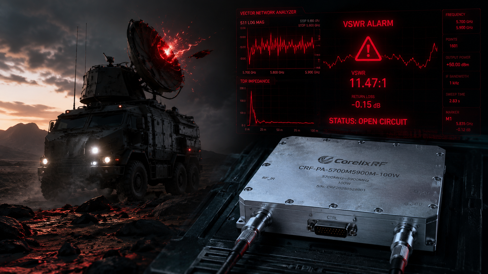
Troubleshooting Mobile Radar Signal Anomalies: The Ignored Consequences of Accidental Antenna Damage or Open Circuits Triggering Reverse Energy Flow and Thermal Runaway. You stare at a spectrum analyzer screen showing severe noise floor collapses during tactical vehicle deployment. Field mechanics accidentally crushed an external radiator while navigating harsh off-road terrain last night. Your display immediately flashed multiple VSWR alarms. A faint smell of burnt epoxy drifts from that sealed electronics enclosure. Hardware destruction happens within milliseconds under these harsh conditions. Here’s the deal. Our engineering team provides a definitive method for isolating these catastrophic mismatch faults. I have spent twenty years diagnosing burnt gallium nitride transistors inside mobile aerospace equipment. We engineered our CorelixRF CRF-PA-5700M5900M-100W module explicitly for surviving massive energy reflections. This guide explains physical mechanisms behind component failure.
1. What Causes Mobile Radar Signal Anomalies During Field Deployments?
Identifying root problems across rugged terrain
Mobile radar systems constantly endure brutal shock profiles across rocky environments. Constant vibration loosens RF connectors over a period of weeks. Water ingress causes severe impedance shifts within a primary transmission line. These mechanical stresses degrade delicate coaxial joints connecting external radiators. What’s the real story? An unexpected tree branch strike can shear a radiator completely off its base. This leaves your final amplification stage staring into an infinite mismatch condition. Frontline operators rarely notice physical damage immediately. They only see target tracking dropouts on their primary console. A technician might assume software glitches caused those unexpected radar blind spots. True engineering reality dictates a hardware-level investigation first. We must look at physical connections before blaming DSP algorithms.
The physical toll on high-vibration environments
Shock and vibration destroy poorly designed microwave assemblies rapidly. Solder joints fracture under continuous cyclic loading causing intermittent electrical contact. An intermittent connection acts like a rapid-fire open circuit generating chaotic reflection spikes. Reflected energy returns backward causing chaotic standing waves inside a transmitter cabinet. Ready for the good part? Engineers can identify these mechanical failures using basic physical inspection techniques. Grasping an external coaxial cable firmly and shaking it reveals hidden breaks. A sudden drop in transmit power during physical agitation confirms structural internal failure. We demand rigorous mechanical testing for all tactical radio frequency hardware. Ignoring vibration specifications guarantees system failure during active combat deployments.
Recognizing false VSWR flags via spectrum analyzers
Inexperienced operators frequently misinterpret spectrum analyzer readings during field operations. A high noise floor often masks true return loss measurements completely. You might see what looks like a failed amplifier when an antenna actually broke. An open circuit at an antenna feedpoint reflects all broadband noise backward. This is where it gets interesting. This returning noise raises your observed baseline obscuring actual transmitted carrier waves. We train technicians for reading these specific spectral signatures accurately. A flat unmodulated wideband noise plateau indicates a totally severed output connection. True engineers verify VSWR using dedicated directional couplers instead of trusting simple spectrum sweeps. Accurate fault isolation prevents replacing perfectly functional amplifier modules unnecessarily.
Field Diagnostics Parameters | Detection Method | Typical Signature
Sheared Radiator | Visual Inspection | Missing Hardware
Fractured Coaxial Center Pin | VNA TDR Sweep | Sharp Inductive Spike
Intermittent Solder Joint | Agitation Test | Bouncing Return Loss
Water Ingress Corrosion | VNA Frequency Sweep | Broad Impedance Dip
2. How Do Open Circuits Trigger Reverse Energy Flow?
The physics driving infinite VSWR states
Radio frequency energy travels outward seeking a matched fifty ohm load. An abruptly broken feedline presents massive discontinuity for traveling waves. All forward power instantly rebounds back toward that fragile output transistor. But here’s the kicker. A one hundred watt signal traveling backward creates devastating standing waves. Voltage peaks align constructively across that transmission line length. This quadruples normal operating voltage limits inside a final amplifier stage. Dielectric breakdown occurs rapidly inside internal matching capacitors. Transistor drain junctions experience voltages far exceeding their absolute maximum ratings. We see cratered gallium nitride dies under scanning electron microscopes regularly. Engineering physics demands an exact impedance match for safe power transfer. A sheared cable violates this fundamental microwave principle completely.

Tracing reflected waves through transmission lines
We track these destructive reflections using advanced time domain reflectometry. An incident wave hits that severed connection point and reflects completely. Phase angles shift depending on exact physical distance from an amplifier. This returning wave combines with new forward power generating massive voltage nodes. System integrators often underestimate how quickly this reflection destroys internal components. Let that sink in. Proper directional couplers can detect this returning wave instantly. Our engineering designs incorporate these reverse power detectors explicitly. Pin 7 on our D-Sub interface provides a precise zero to three volt analog signal. This voltage represents exact reversed RF power levels in real time. Technicians monitor this pin directly using standard multimeters during field diagnostics. Continuous monitoring prevents catastrophic failure from unchecked energy rebounds.
Why isolators fail under extreme mismatch
Many designers rely on ferrite isolators expecting complete component protection. These magnetic devices absorb reflected energy into an internal termination resistor. A hundred watt reverse wave easily overwhelms typical fifty watt internal dump resistors. That internal resistor burns out causing complete isolator failure rapidly. Now, consider this. Once an isolator fails, subsequent reflections travel freely back into active amplifying devices. We cannot trust external isolators alone for high power mobile applications. Active reverse power monitoring offers far superior protection against catastrophic faults. Our CRF-PA-5700M5900M-100W utilizes active detection circuitry instead of relying purely on passive isolation. This approach guarantees survival even when external cables suffer complete decapitation. True hardware reliability requires active awareness of output port conditions.
Reflection Parameter | VSWR Ratio | Return Loss (dB) | Power Reflected (%)
Perfect Match | 1.0:1 | Infinity | 0
Good Match | 1.5:1 | 14.0 | 4.0
Moderate Mismatch | 2.0:1 | 9.5 | 11.1
Severe Mismatch | 3.0:1 | 6.0 | 25.0
Open Circuit | Infinity | 0.0 | 100.0
3. What Are Symptoms Of Thermal Runaway In Mobile Radar?
Reading sudden current spikes via oscilloscopes
Thermal runaway begins silently inside an active device junction. Reflected RF power creates excess heat dissipation within a semiconductor die. Heat lowers internal electrical resistance across transistor channel structures. Lower resistance draws significantly higher current from your main twenty eight volt supply. It gets better. This higher current generates even more localized heating across your gallium nitride chip. You will see operating current spike well past our twenty ampere maximum limit. An oscilloscope monitoring a current shunt reveals rapid exponential current climbing. Unprotected systems will blow main supply fuses within fifty milliseconds. A vigilant engineer measures DC current draw continuously during field testing. Any unexplained current surge indicates massive mismatch or imminent thermal destruction. Real engineering requires tracking dynamic current waveforms during active radar pulsing.
Analyzing baseplate temperature gradients
Heat spreads unevenly across an amplifier baseplate during severe mismatch events. We utilize thermal imaging cameras for visualizing these dangerous hot spots. Normal operation at one hundred watts output produces uniform thermal gradients. An open circuit concentrates intense heat directly underneath final stage output transistors. Here’s the deal. Localized temperatures can exceed one hundred degrees Celsius within seconds. Our CRF-PA-5700M5900M-100W provides a dedicated analog temperature output on pin fourteen. This Tc pin delivers voltage directly corresponding toward actual internal temperature at ten millivolts per degree. Engineers map this signal against known safe operating areas. A sudden voltage spike on pin fourteen confirms severe localized thermal stress. System controllers must read this analog voltage continually during mobile deployment.
Recognizing cascade effects on transistor junctions
Excessive junction temperature degrades semiconductor electron mobility dramatically. RF gain drops sharply as physical device temperature climbs higher. This gain compression reduces total output power unexpectedly during normal radar operation. Operators notice reduced effective radiated power without understanding underlying physical causes. What’s the real story? Continued operation under these conditions permanently alters transistor doping profiles. Metal migration occurs along microscopic gate structures causing irreversible hardware degradation. Your once reliable radar system becomes permanently deaf across its target range. We prevent this cascade effect using integrated hardware protection circuits. A fast acting thermal shutdown mechanism remains non-negotiable for military-grade electronics. Engineers cannot rely on slow software polling loops for hardware survival.
Temperature Output (Tc Pin 14) | Baseplate Temp (°C) | System Action Required
— | — | — 250 mV | 25 | Normal Operation 500 mV | 50 | Monitor Cooling 750 mV | 75 | Increase Fan Speed 850 mV | 85 | TA Alarm Active 900 mV | 90 | Hardware Shutdown
4. How Can We Diagnose Antenna Damage Using Field Instruments?
Using a VNA sweeping for impedance collapse
Vector network analyzers remain our primary weapon against hidden antenna faults. We disconnect our main RF output cable and attach standard VNA test port cables. Sweeping frequencies between 5700 and 5900 MHz reveals true antenna health immediately. A healthy radiator shows return loss better than fourteen decibels across our band. Ready for the good part? A damaged structure exhibits an elevated noise floor and completely flattened resonance curves. You might see return loss hover around two decibels indicating near total reflection. This specific VNA trace confirms mechanical breakage within an external feed structure. Calibrating your analyzer properly at that exact connector interface removes cable losses. We always verify calibration validity using standard open short load standards first. Accurate VNA measurements separate true antenna failures from intermittent cable faults.
Interpreting time-domain reflectometry faults
Modern vector network analyzers feature specialized time domain transformation capabilities. This mode converts frequency sweep data into a physical distance measurement. An engineer can pinpoint exact damage locations along a coaxial cable run. A sharp impedance spike appearing two meters away indicates a crushed cable segment. This is where it gets interesting. You can distinguish between water ingress and a completely severed center conductor. Water shows up as a gradual impedance dip across several inches. A severed wire produces an abrupt inductive or capacitive spike on your display. Mobile radar vehicles often suffer pinched cables passing through armored bulkhead fittings. Finding these hidden faults saves hours of unnecessary vehicle teardown time.
Isolating feedlines from final radiators
Systematic troubleshooting demands isolating individual components systematically. We never test a complete antenna system as one monolithic block. You must separate that primary feed cable from an actual radiating element. Testing that cable separately into a known fifty ohm dummy load proves its integrity. But here’s the kicker. If your cable passes, that fault lies solely within an antenna structure. Sometimes harsh vibrations shatter internal ceramic matching networks inside radomes. Shaking an antenna vigorously while monitoring VNA traces exposes intermittent internal connections. A bouncing return loss trace during physical agitation proves mechanical internal failure. Replacing an entire mast assembly becomes necessary when radome internals shatter.
VNA Fault Signature | Probable Physical Cause | Required Maintenance Action
High Return Loss | Severed Coaxial Cable | Replace Cable Run
Sharp TDR Spike | Crushed Cable Segment | Splice or Replace Section
Broad TDR Dip | Water Ingress / Corrosion | Replace Connector & Seal
Bouncing Trace | Broken Internal Solder Joint | Replace Antenna Assembly
5. Why The CRF-PA-5700M5900M-100W Serves As The Definitive Solution?
Examining our 5700-5900 MHz architecture
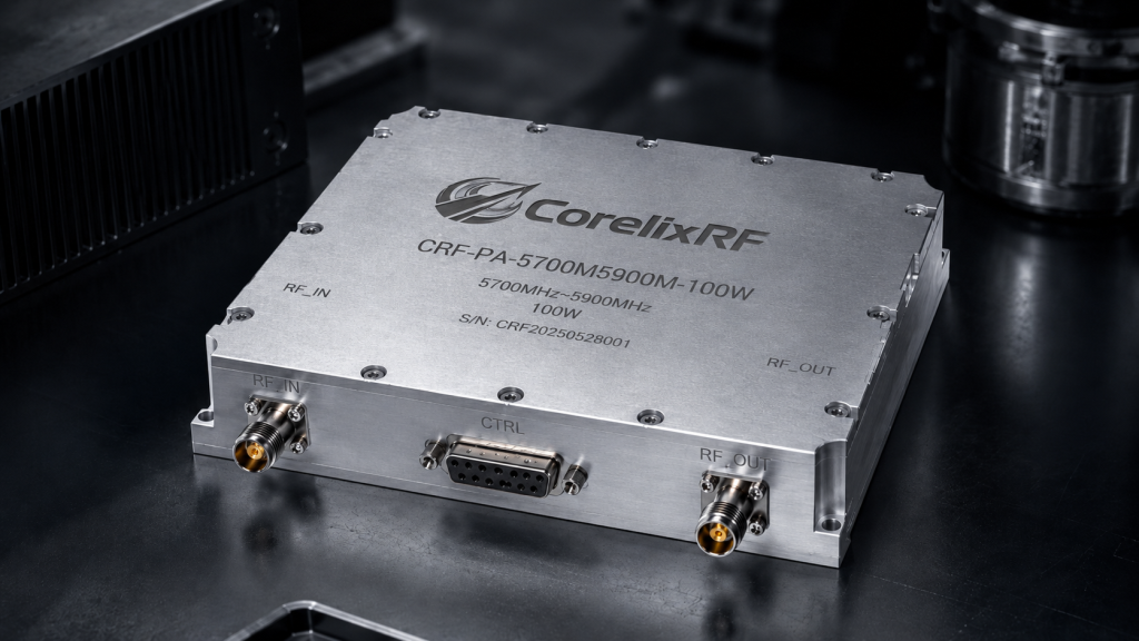
We designed this narrowband RF power amplifier specifically for harsh tactical environments. Operating strictly between 5700 and 5900 MHz allows highly optimized matching networks. We achieve forty eight decibels of typical gain using advanced GaN processes. This targeted frequency band avoids complex wideband compromises that lower efficiency. Let that sink in. Narrowband tuning provides superior harmonic rejection at minus ten decibels carrier. A purely focused architecture reduces unwanted spurious emissions below minus sixty decibels carrier. This clean spectral purity prevents interference with adjacent tactical communication networks. Mobile radar platforms demand this level of spectral discipline during active operations. We guarantee saturated output power reaches one hundred watts minimum consistently.
Understanding integrated hardware protection circuits
Bare transistors die quickly when facing severe field abuse. Our engineering team integrates lightning fast analog protection loops directly inside this module. We monitor forward power, reverse power, operating current, and baseplate temperature simultaneously. These analog loops bypass slow digital microcontrollers entirely for maximum reaction speed. Now, consider this. An active fault triggers hardware shutdown within one hundred microseconds flat. This rapid response saves sensitive GaN dies from catastrophic thermal destruction. A voltage alarm activates instantly when supply inputs exceed thirty two volts. Current alarms trip immediately if operating current spikes beyond twenty2 amperes. We built an electronic fortress around our delicate high frequency amplifying stages.
Integrating D-Sub 15-pin alarm logic
System integrators need clear signals regarding amplifier health status. We provide a comprehensive fifteen pin D-Sub female connector for complete control. Pin 13 delivers a solid five volt logic high during high VSWR events. This VA pin tells a central vehicle computer exactly why transmission stopped. It gets better. Pin 12 provides a similar five volt alarm during over temperature conditions. An operator can attempt an alarm reset using an external pulse on pin 6. This hardware interface allows seamless integration into complex military vehicle databuses. Engineers can build redundant safety protocols using these discrete analog warning flags. You control RF emission completely by floating or driving pin 11 high.
D-Sub 15-Pin Interface | Pin Function | Operating Voltage / Logic Level
| Pin 2 | Over-Voltage Alarm | 5V Logic High (Active > 32V) Pin 3 | Over-Current Alarm | 5V Logic High (Active > 22A) Pin 12 | Over-Temp Alarm (TA) | 5V Logic High (Active on shutdown) Pin 13 | VSWR Alarm (VA) | 5V Logic High (Active on Open/Short)
6. How Does This Amplifier Handle Severe Mismatch Scenarios?
Analyzing VA pin behavior during open circuits
A sheared antenna cable creates an instant open circuit condition. Reflected power surges backward hitting our internal directional coupler immediately. Our hardware comparator detects this reverse voltage exceeding preprogrammed safety thresholds. Pin 13 transitions from zero volts straight toward five volts rapidly. Here’s the deal. This VA signal indicates output port open or short conditions flawlessly. Vehicle control systems read this high state and log a major hardware fault. The amplifier ceases RF generation simultaneously preventing self destruction. We designed this specific pin logic for rapid diagnostic field identification. Mechanics know exactly where they should focus repair efforts based upon this flag.
Executing rapid shutdown sequencing under 100 microseconds
Millisecond level delays cause permanent semiconductor damage during full reflection. We engineered a proprietary analog gate bias cutoff circuit for extreme speed. Our protection loop drops gate voltages deep into pinch-off territory instantly. Total PA disable time clocks in well under one hundred microseconds. What’s the real story? This staggering speed starves a transistor of current before heat can accumulate. The RF output drops toward zero before destructive standing waves stabilize. We tested this shutdown mechanism against thousands of repeated short circuit events. The CRF-PA-5700M5900M-100W survives intentional dead shorts at full output power repeatedly. True engineering reliability means surviving inevitable human errors during field deployment.
Maintaining operational stability at 100W rated output
Pushing one hundred watts of microwave energy requires extreme electrical stability. Low frequency oscillations often plague high power amplifiers under varying load conditions. We utilize heavy decoupling networks on all power supply bias lines. This prevents RF energy from leaking back into a main vehicle power bus. Ready for the good part? Our SMA-KFD46 connectors maintain perfect fifty ohm geometry minimizing insertion loss. We guarantee maximum input VSWR stays strictly below a 1.5 ratio. This tight input match makes cascading pre-driver stages simple and highly predictable. You can drive this unit with minimal input power achieving full saturation easily. System stability remains rock solid even across wide temperature variations.
7. What Mechanical Advantages Prevent Field Failures?
Analyzing our 160 × 120 × 25 mm footprint
Space constraints dictate hardware selection inside modern armored vehicle turrets. We condensed one hundred watts of RF power into a remarkably compact package. A total volume of 160 × 120 × 25 mm allows extremely flexible mounting options. This low profile chassis fits tightly against internal vehicle cooling bulkheads easily. This is where it gets interesting. Weighing strictly under 1.4 kilograms reduces overall system payload significantly. We CNC machine every housing from solid aerospace grade aluminum blocks. This rigid structure prevents chassis flexing under extreme mechanical shock profiles. Internal microwave substrates remain completely flat avoiding microscopic solder joint fractures. A compact dense block survives brutal vibration testing far better than stamped enclosures.
Proving SMA-KFD46 connector reliability under shock
Standard SMA connectors fail rapidly when subjected toward heavy lateral forces. We exclusively specify SMA-KFD46 variants for both input and output RF ports. These specialized connectors feature a robust four hole flange mounting system. Heavy duty stainless steel construction resists thread stripping during rushed field maintenance. But here’s the kicker. A thicker center pin design withstands higher mating cycles without structural degradation. Vibration cannot loosen a correctly torqued four hole flange assembly easily. Our M version utilizes this connector strictly for RF input ports. Output ports feature this same ruggedized interface handling full power effortlessly. Reliable microwave connections demand superior mechanical hardware choices.
Securing external heat sink interfaces
Removing hundreds of watts of waste heat requires perfect thermal mating surfaces. Our 25 mm thick chassis provides an incredibly flat bottom mounting surface. Engineers must apply high quality thermal compound before attaching an external heat sink. We milled precision mounting holes directly into our outer chassis flange. Let that sink in. Secure bolting prevents thermal boundary layer expansion during severe vehicle vibration. A loose amplifier creates microscopic air gaps destroying heat transfer efficiency completely. Operating temperatures range from minus forty up toward plus sixty degrees Celsius safely. Proper mechanical installation guarantees internal junctions never exceed their safe operating limits. CorelixRF provides complete mechanical outline drawings for exact integration reference.
8. How To Implement RS485 Monitoring For Preventive Maintenance?
Configuring master-slave communication buses
Modern radar platforms require constant telemetry regarding subsystem health. We offer an optional RS485 communication bus on pins 1 and 8. This differential serial link provides high immunity against severe electromagnetic interference. A central vehicle processor acts as master polling our amplifier continuously. Now, consider this. You can string multiple modules along a single twisted pair wire. This reduces complex wiring harnesses inside tight vehicular equipment bays. Digital polling reads exact operating voltages directly from internal analog to digital converters. System architects build custom dashboard displays showing real time amplifier telemetry. Preventive maintenance becomes possible when tracking long term parameter drifting trends.
Tracking forward and reversed RF power digitally
Analog voltage pins work well but digital telemetry offers superior data logging. Our RS485 interface transmits calibrated forward and reverse power readings directly. You can monitor actual output wattage without connecting external in-line power meters. Tracking reverse power digitally reveals slow antenna degradation over several months. It gets better. An accumulating layer of salt spray gradually increases antenna VSWR slightly. Digital monitoring flags this gradual deterioration long before catastrophic failure occurs. A maintenance crew can clean an antenna radome proactively based upon telemetry data. This shifts radar maintenance from reactive emergency repairs toward scheduled preventive actions. Digital insight prevents unexpected mission aborts during critical tactical operations.
Setting variable gain and over-temperature thresholds
Dynamic tactical environments often require rapid transmitter power adjustments. Our RS485 link allows remote gain adjustment across a twenty decibel range. You can command zero point five decibel step changes on the fly. This precision control optimizes radar cross section detection ranges automatically. Here’s the deal. Engineers can also modify specific alarm thresholds via this digital interface. You can tighten thermal shutdown limits if operating in extreme desert climates. Remote alarm resetting clears temporary fault conditions without requiring physical technician access. Full digital control elevates a simple RF amplifier into a smart system node. CorelixRF engineers provide complete communication protocols upon request.
9. What Are Engineering Best Practices For Mobile Radar Integration?
Aligning voltage supplies for 28V nominal operation
Gallium nitride transistors operate most efficiently at specific drain voltages. We specify twenty eight volts nominal for our CRF-PA-5700M5900M-100W module. Mobile vehicle power buses often fluctuate wildly between twenty four and thirty two volts. Large alternator load dumps cause massive voltage spikes across a power distribution network. What’s the real story? We recommend installing dedicated DC-DC conditioning regulators before our amplifier power inputs. A regulated twenty eight volt supply guarantees consistent RF output power under varying engine RPMs. Our internal protection circuits will shutdown operation if voltage exceeds thirty two volts. Relying on raw vehicle battery voltage invites intermittent radar dropouts during engine cranking. Clean power remains fundamental for reliable high frequency microwave amplification.
Implementing rigorous grounding strategies
Stray ground loops wreak havoc upon sensitive microwave electronics. An armored vehicle chassis presents varying electrical resistance depending upon welded joints. We require tying our amplifier chassis directly into a main star ground point. Pinning a D-Sub ground return directly toward a clean battery negative eliminates voltage offsets. Ready for the good part? Floating grounds cause false triggering on our five volt logic alarm pins. RF energy must have a solid return path for maximum stability. We designed a dedicated grounding post explicitly for heavy gauge copper braid attachment. Proper grounding lowers system noise floors dramatically improving weak radar return detection. Experienced integrators never underestimate a heavy low impedance ground strap.
Verifying system integrity before field deployment
You must validate all protection mechanisms before sending radar units into combat zones. We instruct clients to simulate antenna failures during final factory acceptance testing. Deliberately disconnecting an output cable tests our 100 microsecond shutdown loop accurately. A technician monitors the VA pin transition on a storage oscilloscope. This is where it gets interesting. Injecting an over-voltage condition verifies our internal power supply protection circuitry. Testing these edge cases guarantees hardware survival when actual battlefield damage occurs. A rigorous testing methodology exposes weak wiring harness crimps or bad logic programming. Our datasheet test conditions assume a perfect fifty ohm system initially. You must prove our hardware reacts correctly when that perfect system breaks completely.
10. How Can CorelixRF Support Specific Hardware Integration Needs?
Leveraging rapid technical feasibility reviews
Standard products rarely fit complex military architectures perfectly. We understand unique mechanical constraints require custom connector placements. Our engineering team provides detailed feasibility reviews within forty eight hours. You submit specific control interface requirements and we modify our internal logic boards. But here’s the kicker. We can shift our operating frequency bands slightly for classified customer requirements. Changing an output connector toward a different ruggedized standard happens frequently. Direct communication with our factory engineers bypasses typical sales channel delays completely. We speak pure engineering truth regarding what physics will actually allow. You get honest answers regarding thermal dissipation limits and maximum saturated power output.
Reviewing test data and customized pattern files
Blindly trusting a printed datasheet leads toward poor system level design. We supply comprehensive test data packages for rigorous project review. You receive actual swept VNA plots showing gain flatness across 5700-5900 MHz. We provide precise thermal camera imagery proving our internal heat spreading calculations. Let that sink in. Customized pattern files help mechanical engineers model exact chassis airflow dynamics. Supplying STEP files early allows seamless virtual integration into vehicle CAD assemblies. We believe transparent data sharing builds deep trust with radar system architects. Our test benches run twenty four hours generating reliability data constantly. Real engineering requires cold hard empirical data.
Partnering for custom high frequency bands
We constantly push our manufacturing capabilities higher into millimeter wave spectrums. While this module targets 5.8 GHz, our expertise spans much wider ranges. We are actively expanding our portfolio into 18–40 GHz bands. Tactical communications require increasingly higher frequencies for wider bandwidth data links. Now, consider this. Partnering directly with CorelixRF secures your supply chain for future system upgrades. We maintain strict ISO 9001 and GJB 9001C quality frameworks across all production lines. This compliance guarantees unit to unit consistency during high volume manufacturing runs. We are not just a vendor but a true RF engineering partner. Contact us today for discussing your next generation mobile radar platform.
Troubleshooting Mobile Radar Signal Anomalies: The Ignored Consequences of Accidental Antenna Damage or Open Circuits Triggering Reverse Energy Flow and Thermal Runaway Ignoring field antenna damage guarantees catastrophic amplifier destruction. We explored how infinite standing waves obliterate standard components instantly. Implementing active hardware protection represents your only viable defense strategy. The CorelixRF CRF-PA-5700M5900M-100W delivers unmatched reliability through lightning-fast shutdown loops. Contact our engineering team today for integrating this 100W module into your mobile radar architecture.
FAQ
Q1: What is the frequency range of the CRF-PA-5700M5900M-100W? The CRF-PA-5700M5900M-100W operates precisely between 5700 and 5900 MHz.
Q2: How does the VSWR alarm (VA) work? A reverse power comparator triggers pin 13 to a 5V logic high during open or short conditions.
Q3: What is the maximum operating current? The amplifier draws a typical 16A, with an absolute maximum rating of 20A at 28V.
Q4: How fast does the PA disable upon a fault? Hardware protection circuits disable RF output in under 100 microseconds.
Q5: What are the dimensions and weight of this amplifier? The compact chassis measures 160 × 120 × 25 mm and weighs less than 1.4 kg.