
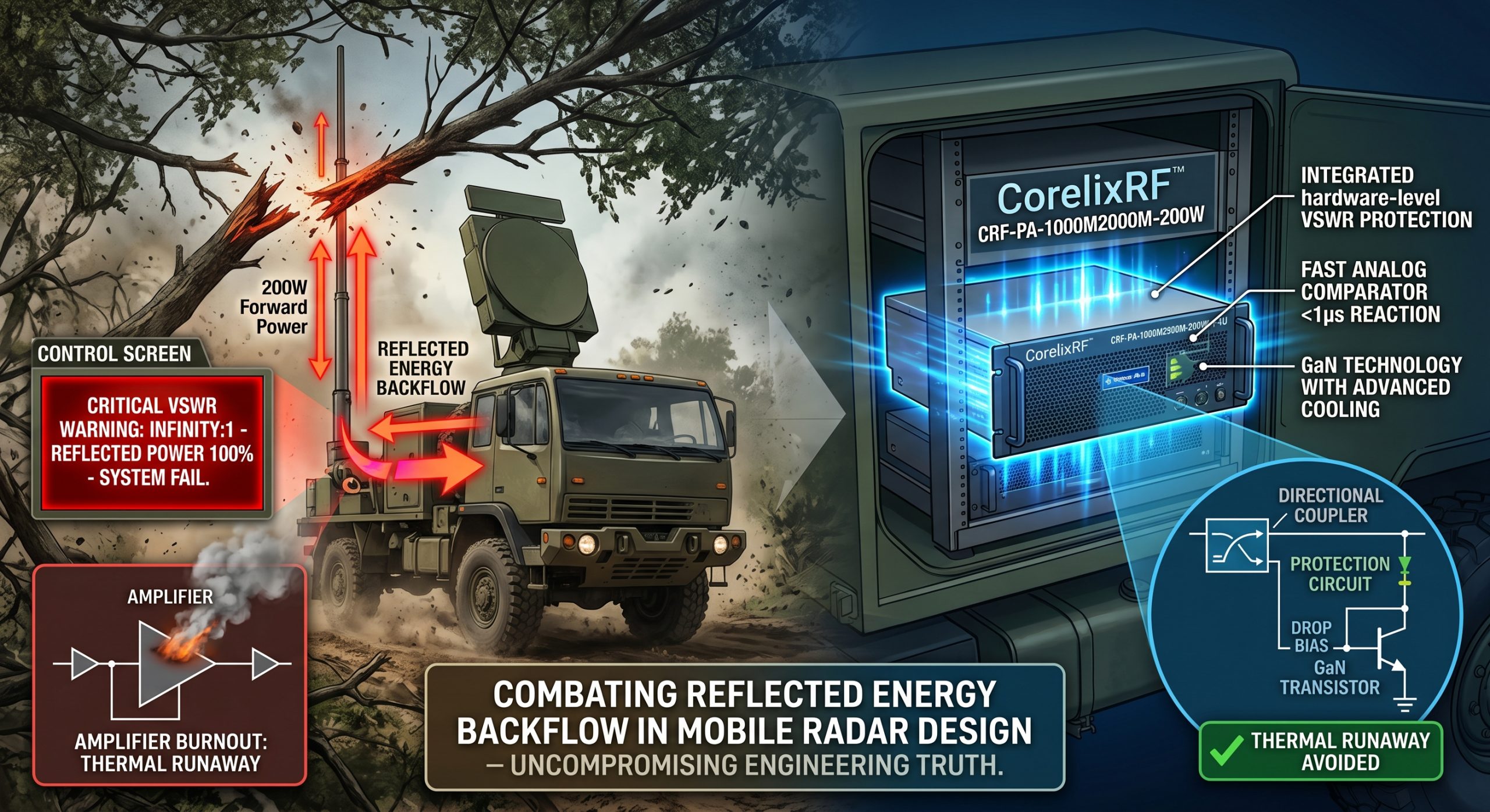
Mobile radar hits a low-hanging branch violently. An exposed antenna snaps off completely. Your control screen flashes a red VSWR warning instantly. Output power plummets toward zero. That expensive final amplification stage faces massive reflected energy. Heat accumulates rapidly within milliseconds inside semiconductor junctions. Smoke appears quickly. Your mission ends right there. We engineered our CRF-PA-1000M2000M-200W specifically against such catastrophic physical realities. CorelixRF relies purely on uncompromising Engineering Truth.
1. What Causes Reflected Energy Backflow In Mobile Radar Systems?
● Physical Damage Mechanics
Here’s the deal. High-frequency vibration ruins fragile mechanical connections continuously. Rough terrain constantly stresses rigid coaxial cables during transport. A sudden physical impact often breaks an exposed radiator element. Impedance mismatch happens instantly when that physical geometry changes. Forward RF power no longer radiates into free space efficiently. That 200W signal hits an open circuit suddenly. Physics dictates returning energy must go somewhere immediately. Voltage standing waves build up along transmission lines rapidly. Maximum voltage peaks exceed component breakdown ratings easily. Reflection coefficients spike near unity during total disconnects.
● Electromagnetic Propagation Factors
Power travels backwards toward your amplification stages relentlessly. You might be wondering. Why does this happen so incredibly fast? Electromagnetic waves propagate near light speed constantly. Your hardware experiences extreme stress before software detects any fault. We see this exact scenario constantly during hostile field deployments. Our engineering team measures these reverse spikes using fast oscilloscopes. Standard commercial equipment cannot survive such brutal operating conditions. They fail catastrophically under severely mismatched loads. Our laboratory tests prove this vulnerability conclusively. You must account for dynamic impedance shifts. Mobile platforms vibrate constantly. Cables degrade over extended deployment cycles. Connectors loosen imperceptibly over months of rough usage. Water intrusion alters dielectric constants unpredictably. Every single factor contributes toward increasing reflected power.
| Parameter | VSWR Value | Return Loss (dB) | Reflected Power (%) | System Impact |
| Ideal Match | 1.0:1 | Infinity | 0.0% | Normal operation |
| Minor Degradation | 1.5:1 | 14.0 | 4.0% | Normal specification |
| Moderate Damage | 3.0:1 | 6.0 | 25.0% | Heating increases |
| Severe Damage | 5.0:1 | 3.5 | 44.4% | Risk of breakdown |
| Open Circuit | Infinity | 0.0 | 100.0% | Catastrophic failure |
2. How Does Antenna Damage Trigger Thermal Runaway?
● localized Heating Phenomena
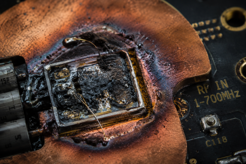
What’s the real story? Reflected power creates massive localized heating. Transistor junctions inside your amplifier absorb returning RF energy. This unexpected load drastically reduces operating efficiency. Input DC power converts directly into heat instead of forward transmission. Channel temperatures inside semiconductor dies spike beyond safe limits quickly. Gallium Nitride devices handle higher temperatures than older technologies. Extreme mismatches still cause rapid degradation regardless.
● Positive Feedback Loops
It gets worse. Increased heat lowers device efficiency further. That creates a deadly positive feedback loop. We call this phenomenon thermal runaway. Junction temperatures can exceed 200 degrees Celsius within seconds. Solder joints melt completely. Gold bond wires inside component packages fuse open. Active cooling systems cannot react fast enough against instantaneous transient spikes. Engineers must design robust hardware-level protection mechanisms. Software polling rates remain too slow for real-time safety. You need dedicated analog sensing circuits. Thermal inertia prevents heatsinks from absorbing instantaneous energy bursts. The localized die temperature determines transistor survival exclusively. A massive aluminum block helps during continuous operation. It does nothing for microsecond-level transients. We engineer direct copper attachment methods for maximum thermal transfer. Our factory measures these thermal gradients using infrared microscopy. We observe hotspot formation during simulated antenna failures. This empirical data drives our mechanical layout decisions.
3. Why Do Standard Amplifiers Fail During Open Circuits?
● Missing Isolation Components
Let’s dig deeper. Cheap consumer-grade designs skip critical isolation components constantly. They connect final amplification stages directly toward output ports. A severed cable reflects almost 100% of transmitted energy backwards. Those returning waves create constructive interference with forward signals. Voltage peaks puncture gate oxides inside expensive RF transistors. Hardware dies silently.
● Slow Digital Polling
Here is the kicker. Many competitors use slow microcontroller-based VSWR polling. A typical microprocessor requires several milliseconds for reading analog sensors. Transistors die in microseconds during severe load mismatches. Relying entirely upon digital firmware loops guarantees eventual hardware failure. We analyze destroyed units from other vendors frequently. Their printed circuit boards show extensive carbon scoring around final stages. Lack of proper directional couplers leaves them blind. They simply cannot detect reverse power fast enough. True engineering requires anticipating total physical disconnection. You cannot assume an ideal 50-ohm match outside laboratory environments. We utilize specialized high-directivity couplers on our output networks. These passive components provide exact analog voltage representations of reflected waves. This allows instant hardware-level intervention. We bypass slow digital logic entirely for critical fault protection. Our systems survive while competitor units burn.
| Protection Type | Reaction Time | Intervention Method | Reliability Level |
| Firmware Polling | > 5 milliseconds | Software Interrupt | Low |
| Digital DSP | 1 millisecond | Logic Gate | Medium |
| Analog Comparator | < 1 microsecond | Hardware Bias Cut | Very High |
| Isolator/Circulator | Instantaneous | Magnetic Routing | Absolute |
4. How Does System Architecture Influence L-Band Radar Reliability?
● Frequency Band Challenges
Think about this. Operating between 1000 and 2000 MHz brings unique challenges. Mobile search radars require wide bandwidths for frequency hopping techniques. Maintaining flat gain across a full octave demands complex matching networks. Those passive matching components introduce insertion losses naturally. High continuous wave outputs generate immense thermal loads continuously. Your system architecture must account for worst-case environmental factors constantly.
● Electromagnetic Layout Precision
This is where it gets interesting. We designed specifically for L-band tactical deployments. Radar systems demand absolute phase linearity and amplitude stability. Even minor impedance shifts distort delicate pulse compression waveforms. Poor system architecture degrades target resolution significantly. Our engineers utilize advanced electromagnetic simulation tools during layout phases. We carefully control parasitic capacitances along every RF trace. Component placement dictates overall system survivability under high stress. A robust architecture separates delicate exciter circuits from high-power stages physically. We maintain strict isolation between sensitive receiver paths and transmitter outputs. We use specialized RF absorbers inside the chassis cavity. This prevents internal cavity resonances from causing spurious emissions. Harmonic content remains strictly controlled below -10 dBc. We deliver clean spectrum profiles for demanding aviation control applications.
5. What Role Does VSWR Protection Play In Field Operations?
● Environmental Variables
Listen closely. VSWR protection acts as your absolute last line of defense. Field operations involve unpredictable variables like rain or dirt. Debris covering an antenna alters its resonant frequency drastically. This subtle detuning increases reflected power gradually over time. A reliable protection circuit monitors both forward and reverse power continuously. Our factory calibrates these sensors rigorously.
● Autonomous Hardware Response
Ready for the good part? Our proprietary analog comparator network reacts almost instantly. It drops gate bias voltages within nanoseconds upon detecting dangerous reflections. This immediate shutdown saves thousands of dollars in replacement costs. We do not rely on software interrupts for critical survival functions. The hardware takes autonomous action before thermal limits are reached. Our modules feature an automatic recovery sequence after faults clear. Operators do not need manual reset procedures during intense missions. We ensure your mobile radar stays operational despite hostile environmental conditions. Built-in protection handles over-voltage and over-temperature events seamlessly. Engineering truth means building resilient systems capable of autonomous self-preservation. Human intervention is too slow.
| Sensor Type | Monitored Parameter | Action Triggered | Recovery Mode |
| Directional Coupler | Reverse RF Power | Drop Gate Bias | Auto-retry |
| Thermistor | Baseplate Temp > 50°C | Reduce RF Drive | Auto-resume |
| Current Shunt | Supply Current | Disconnect DC | Manual Reset |
| Voltage Monitor | VDD > Limit | Trigger Crowbar | Manual Reset |
6. How Does The CRF-PA-1000M2000M-200W Address These Pain Points?
● Core Performance Metrics
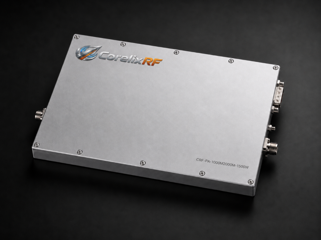
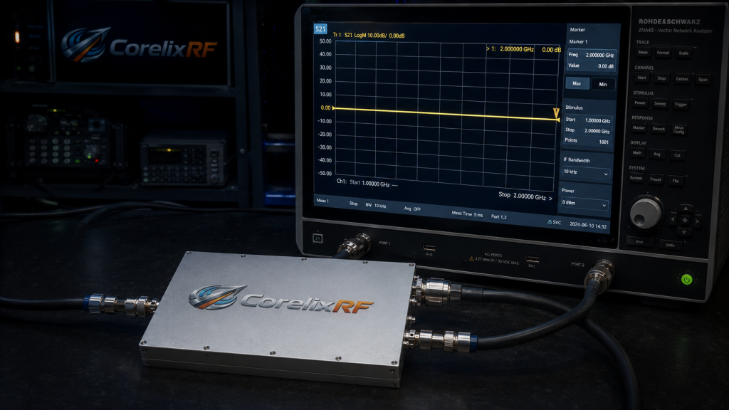
Let’s get specific. The CorelixRF CRF-PA-1000M2000M-200W delivers 200W rated output power across 1-2 GHz. We built this specific model utilizing advanced GaN technology. It provides 53dB gain with strict flatness controls spanning just 3dB. You can adjust gain dynamically up to 20dB.
● Mechanical and Electrical Integration
But wait, there’s more. We integrated over-voltage, over-temperature, over-drive, and VSWR protections directly. Our design team focused heavily on surviving extreme mismatch conditions. We utilize heavy-duty N-Female connectors for both input and output ports. These robust mechanical interfaces withstand severe vibration profiles easily. The unit consumes roughly 1000W of AC power during maximum transmission. We implemented a high-efficiency air cooling system within the 4U chassis. This ensures stable operation up to 50 degrees Celsius ambient. RS485 and LAN interfaces offer comprehensive remote control capabilities. We supply this equipment for test, measurement, communication, and aviation control applications. We strictly adhere to ISO 9001 and GJB 9001C quality frameworks. We deliver industrial-grade reliability consistently.
7. What Are The Key Hardware Components Preventing Component Burnout?
● Sensing and Logic Circuits
Pay attention to this. High-power directional couplers form the heart of our sensing mechanism. They sample a tiny fraction of reverse traveling waves accurately. Fast analog detectors convert that RF sample into measurable DC voltages. High-speed comparators evaluate those signals against precise reference thresholds continuously. They act definitively.
● Material Science Applications
Here is the bottom line. We utilize drop-in circulators for absolute isolation where applicable. However wideband L-band operation often precludes simple narrow-band ferrite devices. Therefore we engineered ruggedized matching networks capable of absorbing transient spikes. Heavy copper coin technology embedded inside our printed circuit boards dissipates heat. Our GaN transistors sit directly upon specialized thermal spreaders. This physical arrangement minimizes thermal resistance between semiconductor junctions and massive heatsinks. We refuse to compromise on baseplate material quality. Every component choice reflects our commitment to ultimate reliability. Standard FR4 substrates simply cannot handle these power density levels. We exclusively use specialized high-frequency laminates for all RF paths. This prevents dielectric breakdown under extreme voltage standing wave conditions. Engineering truth demands superior material science.
| Component | Material / Tech | Function | Failure Resistance |
| RF PCB | Rogers RO4350B | Low-loss propagation | High |
| Baseplate | CuMo Alloy | Thermal expansion match | Excellent |
| Transistor | Gallium Nitride (GaN) | Amplification | Very High |
| Coupler | Stripline Ceramic | Power sampling | High |
8. How Do We Integrate High-Power Modules Into 4U Enclosures?
● Thermal Dissipation Strategies
Picture the scenario. Packaging a 200W continuous wave amplifier requires serious thermal engineering. A 4U 19-inch rackmount chassis offers limited internal volume. We must extract hundreds of watts of waste heat efficiently. A 1000W consumption rate means massive thermal dissipation requirements.
● Structural and RF Layout
Let me explain. Our mechanical engineers utilize computational fluid dynamics software extensively. We optimize airflow pathways across massive aluminum extrusion heatsinks. High-volume industrial fans push cooling air precisely where it matters most. Front panel vents feature EMI shielding preventing unwanted RF leakage. We isolated sensitive power supply modules from high-power RF sections physically. The 20-kilogram weight reflects our heavy-duty construction philosophy accurately. Our internal layout minimizes cable lengths between discrete amplification stages. This strict control over parasitic inductance prevents unwanted low-frequency oscillations. Every coaxial connection utilizes precise torque specifications during factory assembly. We ensure your system withstands rigorous transport across unforgiving terrain. The AC 220V power supply sits securely isolated. Structural integrity prevents connector shear during violent mobile deployments.
9. Why Is Monitoring Vital For Continuous Mission Readiness?
● Real-Time Telemetry Data
Do not ignore this. Operating blindly leads to catastrophic equipment failure eventually. A modern mobile radar demands constant telemetry data streaming. System integrators need real-time visibility into amplifier health metrics. Hardware status dictates tactical decisions.
● Control Interface Flexibility
Here is a secret. The CRF-PA-1000M2000M-200W provides comprehensive status reporting via LAN. Operators monitor forward power, reverse power, and internal temperatures remotely. We offer optional forward/reverse power monitoring capabilities explicitly. RS485 connections allow daisy-chaining multiple units within complex array structures. You can adjust internal gain up to 20dB dynamically via software. This flexibility allows precise power leveling across massive distributed systems. An illuminated front panel alarm LED provides immediate visual fault indication. We engineered our control logic for maximum transparency. We believe hiding diagnostic data hurts field engineers troubleshooting complex issues. CorelixRF delivers uncompromising visibility into hardware performance. You see exactly what the hardware experiences. Our protocol documentation makes system integration straightforward.
| Interface | Connector Type | Primary Function | Data Rate/Standard |
| RS485 | DB9 Female | Serial Telemetry | 9600-115200 bps |
| LAN | RJ45 | Network Control | 10/100 Mbps Ethernet |
| RF IN | N-Female | Signal Input | 50 Ohm |
| RF OUT | N-Female | Power Output | 50 Ohm |
10. What Should Engineers Prioritize During BOM Selection?
● Scrutinizing Technical Specifications
Listen to experience. Selecting RF components based solely on price guarantees disaster. A cheap amplifier module costs ten times more when it fails mid-mission. You must scrutinize datasheets for vague or misleading specifications carefully. Look for guaranteed minimum performance under specific harsh conditions.
● Valuing Engineering Truth
Let me be clear. Verify that VSWR protection mechanisms operate autonomously via hardware. Ask vendors about their thermal derating curves at high ambient temperatures. True Engineering Truth requires transparent testing methodologies and verifiable data. We supply test data and pattern files for rigorous project reviews where applicable. CorelixRF maintains strict RoHS, CE, and FCC compliance standards globally. We build industrial RF solutions meant for brutal physical realities. Our manufacturing history informs every design decision we make. Stop accepting fragile laboratory equipment for rugged tactical deployments. Demand uncompromising quality from your hardware partners. Customization options exist for input power detection and GPIB control interfaces. Build systems that survive.
High-power mobile radars require robust protection against reflected energy. Antenna failures destroy unprotected L-band amplifiers instantly. The CorelixRF CRF-PA-1000M2000M-200W delivers absolute reliability under extreme VSWR conditions. Protect your expensive infrastructure today. Contact our engineering team for customized system integration support. We stand behind our rugged designs fully.
FAQ
Q1: What is the specific frequency range and power output of this amplifier?
The CRF-PA-1000M2000M-200W operates precisely between 1000 and 2000 MHz. It delivers a rated output power of 200W.
Q2: How does the VSWR protection system work?
The system utilizes built-in hardware protection. It monitors reverse power continuously and drops gate bias instantly to prevent component burnout during severe impedance mismatches.
Q3: What kind of cooling method does this unit require?
The amplifier utilizes an integrated air cooling method. Internal fans drive airflow across massive heatsinks inside the 4U chassis.
Q4: Which control interfaces are available for remote monitoring?
Operators can monitor and control the unit using standard RS485 or LAN interfaces. Optional GPIB control interfaces are available via customization.
Q5: What applications is this amplifier designed for?
We designed this unit for test & measurement, communication, interference, and aviation control applications. It suits high-stress mobile environments perfectly.
Turn VSWR behavior into factory acceptance evidence
High VSWR protection should be defined with mismatch scenario, foldback or shutdown threshold, recovery logic, alarm output, thermal limit and FAT evidence. This makes protection claims measurable for procurement.
Recommended next step: send the operating band, output power target, duty cycle, load condition, control interface, protection or thermal limits and required FAT documents. CorelixRF can review this How to Survive Reflected Energy Backflow During Antenna Failures? requirement against standard RF amplifier platforms, RF front-end options and controlled customization paths.