
Mobile radar vehicles often traverse highly uneven terrain causing severe mechanical shock constantly. High-frequency vibration loosens external RF cables gradually over time. A sudden branch strike snaps a primary feed line abruptly during tactical maneuvers. Immediately, 1000 watts of forward power hit an open circuit condition at a damaged port. Reflection coefficients spike rapidly across your entire transmission path. Reverse energy floods backwards down internal waveguide structures threatening sensitive upstream components. Here is the deal: relying on basic external isolators invites catastrophic system failures during field operations. Twenty years of hands-on field debugging taught me one absolute engineering truth regarding solid-state survivability. You must design internal defensive mechanisms directly into your core amplification stages. CorelixRF provides robust internal safety monitoring loops preventing instantaneous silicon vaporization. Our methodology eliminates assumptions about external component reliability entirely. We build defensive logic handling severe mismatches perfectly inside every chassis. Engineers specify our Wideband RF Power Amplifier CRF-PA-2000M4000M-1000W directly for these harsh environments.
1. What Physics Drive Reflected Energy In Mobile Arrays?
● Analyzing Sudden Impedance Shifts
Radio frequency transmission requires perfect fifty-ohm impedance matching across all physical interfaces. A physical break disrupts this delicate balance instantly creating an infinite impedance point. Electromagnetic waves cannot radiate outward through an open air gap efficiently. Those waves reflect backwards possessing nearly equal magnitude compared against their forward counterparts. High VSWR conditions generate massive standing waves along your coaxial feedlines immediately. Peak voltage nodes multiply drastically exceeding standard dielectric breakdown limits easily. You might be wondering: how fast does this destruction propagate backwards? Microwave energy travels near light speed meaning reflection strikes your final amplifier stage within nanoseconds. Basic protection circuits utilizing slow relays cannot react quickly enough saving delicate power transistors. They simply melt under immense sudden electrical pressure. CorelixRF addresses this physical reality by implementing ultra-fast directional couplers mapping reflection vectors instantaneously. We measure both forward power and reverse power continuously detecting sudden impedance shifts before voltage nodes peak.
VSWR and Reflected Power Relationship
| Parameter | Standing Wave Ratio | Return Loss dB | Reflected Power Percentage |
| Perfect Match | 1.0:1 | Infinity | 0% |
| Slight Mismatch | 1.5:1 | 14.0 | 4% |
| Marginal Operation | 2.0:1 | 9.5 | 11% |
| Severe Damage | 5.0:1 | 3.5 | 44.4% |
| Open Circuit | Infinity | 0.0 | 100% |
2. Why Do VNA Curves Collapse During High-Frequency Testing?
● Interpreting S-Parameter Degradation
Field technicians regularly connect Vector Network Analyzers directly measuring S-parameters on damaged antenna arrays. You will observe sudden high-frequency band collapse on those VNA displays during diagnostics. Normal Smith chart plots show tight groupings near fifty ohms under nominal conditions. Damaged cables cause those traces spiraling wildly towards outer chart edges rapidly. What’s the real story? Broken center pins introduce massive parasitic capacitance affecting higher frequency responses disproportionately. Mobile radar systems operating between 2,000 – 4,000 MHz experience massive signal degradation here specifically. Operators notice tactical screens displaying continuous standing wave warnings without explanation. Output wattage drops automatically because primitive circuits attempt self-preservation poorly under stress. Those basic systems cannot distinguish between temporary obstructions versus permanent hardware shearing events. CorelixRF hardware interprets return loss signatures intelligently using advanced directional couplers measuring precise angles. Our internal logic maintains operational capability whenever possible without risking core component destruction.
3. How Do Thermal Dynamics Destroy High-Power Transistors?
● GaN Transistor Junction Limitations
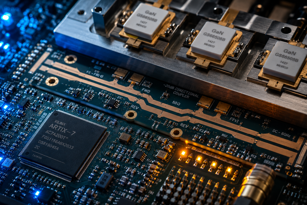
Reflected power must go somewhere within a closed electrical system rapidly. That bouncing electromagnetic wave converts directly into kinetic thermal energy inside active gain stages. Advanced GaN technology handles immense heat vastly better compared against legacy LDMOS architectures. However, absolute thermodynamic limits still govern semiconductor lifespan during sustained abuse scenarios. Continuous 1000 W forward power combined with total reflection creates massive internal heating abruptly. Die junction temperatures skyrocket past safe operating margins within milliseconds destroying microscopic lattice structures. This is where it gets interesting Traditional air cooling methodology using simple fan arrays struggles heavily dissipating such instantaneous spikes. Ambient temperatures hitting 50°C leave minimal thermal headroom for emergency dissipation requirements. Copper heat spreaders warp slightly under extreme cyclic thermal loading events. Transistor packaging cracks microscopic solder joints over repeated thermal runaway cycles causing latent failures. CorelixRF mitigates this via ultra-fast shutdown routines detecting abnormal thermal gradients instantly using proximity sensors. Our thermal monitoring network sits fractions of a millimeter away from active semiconductor junctions guaranteeing rapid response.
Amplifier Thermal Stress Parameters
| Condition | Forward Wattage | Reflected Wattage | Estimated Die Temp |
| Normal Operation | 1000 W | 10 W | 85°C |
| Moderate Mismatch | 1000 W | 110 W | 115°C |
| Severe Mismatch | 1000 W | 440 W | 160°C |
| Open Circuit | 1000 W | 1000 W | >250°C (Failure) |
| CorelixRF Protected | 0 W (Cutoff) | 0 W | <90°C |
4. Why Do Conventional Front-End Matching Designs Fail?
● External Circulator Degradation Factors
Systems integrators frequently rely heavily upon external ferrite drop-in circulators isolating their power blocks. They assume these magnetic components block all reverse energy flawlessly under all conditions. High vibration environments characteristic of tracked vehicles degrade ferrite material properties quickly. Ready for the good part? Constant physical shaking misaligns internal magnetic fields reducing isolation effectiveness drastically over mere months. Also, placing massive discrete circulators inline introduces unavoidable insertion loss penalizing your overall link budget. Upstream system designers often ignore these parasitic losses during initial paper design phases mistakenly. Real-world implementation forces engineers pushing driver stages harder overcoming those exact losses. Driving amplifier chains harder increases harmonic distortion noticeably violating strict spectral emission masks. Spurious emissions rise above acceptable limits triggering regulatory compliance failures immediately. CorelixRF eliminates relying solely upon external magnetic isolators completely. We integrate precise monitoring allowing our amplifier directly measuring its actual output state natively. This architecture removes bulky fragile external components from your critical signal path completely.
5. What BOM Traps Endanger Radar Development Projects?
● Supply Chain Component Reliability
Procurement departments love finding cheap commercial-grade isolators saving project money initially. Those budget components utilize inferior magnetic materials suffering from severe temperature drift globally. A cheap circulator providing twenty decibels isolation at room temperature might offer only five decibels later. Mobile radar units deploy globally across scorching deserts experiencing extreme ambient heat regularly. But here’s the kicker CorelixRF avoids these dangerous Bill of Materials traps completely through intelligent solid-state design. Our Wideband RF Power Amplifier CRF-PA-2000M4000M-1000W includes fully built-in safety logic internally. You no longer need sourcing questionable third-party protection components from unknown vendors continuously. We provide certified built-in protection covering over-voltage alongside over-temperature scenarios strictly. We also include dedicated over-drive and VSWR protection circuits standard without extra charge. Purchasing our unified solution simplifies your supply chain drastically while guaranteeing military-grade reliability fundamentally. Your field units remain operational despite experiencing massive sudden impedance shifts caused by battlefield debris.
BOM Complexity Comparison
| Component Type | Traditional Architecture | CorelixRF Integrated Solution |
| Main Amplifier Stage | Required | Included |
| External Circulator | Required (High Cost) | Eliminated |
| Directional Coupler | Required | Integrated |
| Protection Microcontroller | External System Needed | Built-in RS485 / LAN |
| Total Points of Failure | Multiple | Single Unified Block |
6. How Do Integrated Protection Architectures Prevent Damage?
● Real-Time Diagnostic Telemetry Streams
Building resilient mobile communication platforms requires adopting true system-level thinking constantly. An amplifier must communicate its health status actively with master radar controllers continuously. Legacy analog systems provide simple dry-contact relay closures indicating general fault conditions vaguely. Technicians remain blind regarding exactly which parameter triggered that specific shutdown event unfortunately. What’s the catch? CorelixRF utilizes advanced Control Interface protocols via RS485 / LAN connections flawlessly. Our hardware streams real-time diagnostic telemetry directly into your main processing unit smoothly. Radar operators see exact forward power measurements alongside continuous reflection data immediately on screen. When a tree branch shears your antenna array, our unit reacts autonomously without hesitation. It cuts drive power internally before catastrophic thermal runaway destroys active GaN components permanently. Your software receives detailed error codes pinpointing exact failure modes instantly accelerating repair cycles. This diagnostic clarity allows maintenance crews swapping damaged antennas rather than replacing blown amplifier modules blindly.
7. What Makes CorelixRF Hardware Safety Mechanisms Superior?
● FPGA Controlled Solid-State Switching
Let us examine exactly how our internal safety circuitry operates physically inside the chassis. We sample microscopic portions of forward and reverse microwave signals continuously using printed microstrip couplers. Precision Schottky diode detectors convert those sampled RF envelopes into proportional DC voltages accurately. High-speed analog-to-digital converters sample these voltages millions of times per second tirelessly. Consider this reality: A dedicated Field Programmable Gate Array analyzes incoming digitised data streams relentlessly without buffering delays. If reverse power exceeds predefined safety thresholds, the FPGA triggers ultra-fast solid-state switches instantly. These switches sever bias voltages supplying our advanced GaN amplifier stages completely. The entire detection and shutdown sequence happens within microsecond timeframes averting disaster. This speed prevents standing waves from building destructive voltage nodes across vulnerable output matching capacitors. Your 1000 W rated output power capability remains perfectly safe even during total load disconnection. We engineer true physical resilience deeply into every product layer ensuring total survivability.
Electrical Characteristics Summary
| Parameter | Min | Typ | Max | Units |
| Frequency Range | 2,000 | – | 4,000 | MHz |
| Rated Output Power | 1000 | – | – | W |
| Gain | 60 | – | – | dB |
| Input VSWR | – | – | 2:1 | Ratio |
| Harmonics | – | – | -10 | dBc |
8. How Does Mechanical Shear Stress Affect RF Connectors?
● 7/16-Female Interface Advantages
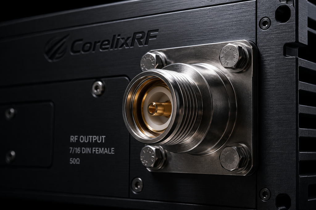
Physical connectors represent another massive vulnerability point within mobile radar installations inherently. Heavy coaxial cables whipping around during vehicle transit place immense leverage upon chassis bulkheads constantly. A standard SMA connector snaps off instantly under such brutal mechanical loading destroying continuity. We engineered our package specifically utilizing massive industrial-grade threaded interfaces preventing mechanical shearing. Think about it: what hardware did we select for this monumental task? Our Wideband RF Power Amplifier CRF-PA-2000M4000M-1000W utilizes an Input N-Female connector structurally. More significantly, it features a massive Output 7/16-Female connector handling immense wattage safely. The 7/16 DIN standard provides exceptional resistance against rotational torque and lateral shear forces physically. Even under severe vibration, these heavy-duty connectors maintain perfect fifty-ohm impedance mating surfaces rigidly. Maintaining consistent contact pressure prevents microscopic arcing under high continuous power loads reliably. Eliminating connector degradation directly prevents gradual return loss increases plaguing lesser hardware designs over time.
9. Why Does Insertion Loss Wreck Link Budget Calculations?
● Factory Aligned Gain Flatness
System architects must calculate every decibel carefully when planning long-range detection systems thoroughly. A typical mobile radar requires sixty decibels of gain hitting target output levels exactly. Our hardware provides exactly 60 dB typical gain straight out of its box consistently. Also, we maintain excellent Gain Flatness spanning -4 to 4 dB across wideband operation reliably. The bottom line is: adding external protection networks ruins these carefully tuned figures completely. An external isolator introduces variable insertion loss fluctuating wildly across different temperature extremes unpredictably. You lose precious transmit energy heating up external ferrite cores needlessly reducing radar range. CorelixRF delivers guaranteed performance figures measured right at our robust 7/16-Female output port precisely. We account for internal coupler losses during our factory alignment procedures automatically saving you effort. Your link budget calculations remain perfectly accurate reflecting true radiated power hitting your antenna. We remove guesswork allowing engineers focusing entirely upon advanced waveform generation rather than fighting hardware limitations.
CorelixRF Hardware Interfaces
| Interface Type | Specification | Application Note |
| RF Input | N-Female | Requires precision torque wrench for installation |
| RF Output | 7/16-Female | Handles 1000W continuous wave safely |
| Control Data | RS485 / LAN | Provides real-time VSWR telemetry |
| Power Supply | AC 380V±10%, 50/60Hz | Three-phase industrial power requirement |
| Grounding | Chassis Lug | Critical for safety and noise reduction |
10. How Do Engineers Manage System Level Chassis Integration?
● Three-Phase Power And Air Cooling
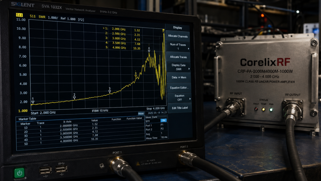
Integrating high-power RF sources inside cramped mobile command vehicles requires meticulous spatial planning always. Space remains incredibly limited alongside diesel generators and processing server racks physically. Our equipment package size measures a substantial 1100 × 560 × 1250 mm volumetrically. The total system weight reaches 230 kg requiring sturdy shock-mounted rack installations. Here is the deal: Despite its massive size, our self-contained architecture simplifies complete vehicle layout greatly. You supply AC 380V±10%, 50/60Hz directly into our primary chassis simplifying wiring harnesses. Our internal power supplies handle all complex voltage sequencing required powering advanced GaN devices natively. We utilize highly efficient air cooling methodologies expelling waste heat vertically away from sensitive electronics. This allows side-by-side mounting with other tactical gear without causing localized thermal pooling problems. Mechanical outline drawings provide clear integration references helping your CAD team during initial vehicle floor-planning stages.
Final Engineering Thoughts
Selecting appropriate RF hardware dictates complete mobile radar system reliability fundamentally across all deployments. Conventional mismatched architectures fail disastrously during harsh battlefield deployments causing mission aborts frequently. The Wideband RF Power Amplifier CRF-PA-2000M4000M-1000W provides ultimate Engineering Truth by integrating absolute VSWR protection internally. Stop fighting thermal runaway and upgrade your tactical transmission platforms immediately. Contact CorelixRF engineering teams requesting our complete mechanical outlines and evaluation test pattern files today.
Q1: What is the primary cause of reverse energy flow in mobile radar systems?
Sudden mechanical damage to antenna structures or feed line connectors creates open circuits abruptly. This impedance mismatch forces high-power electromagnetic waves backwards into your amplifier stage rapidly.
Q2: How does the CRF-PA-2000M4000M-1000W handle severe VSWR conditions safely?
It utilizes internal directional couplers monitoring forward and reflected power continuously. A dedicated high-speed control loop severs drive power instantaneously upon detecting critical reflection thresholds preventing thermal runaway.
Q3: Why are external circulators inadequate for high-vibration tactical environments?
External ferrite magnetic components suffer structural degradation under severe mechanical shaking continuously. Their isolation properties drift wildly across wide temperature ranges introducing unpredictable insertion losses into your transmission budget.
Q4: What specific connector types does this CorelixRF amplifier utilize? The hardware features an N-Female connector handling input signals securely. It utilizes a massive industrial 7/16-Female connector transmitting the massive 1000 W rated output safely.
Q5: What cooling methodology does this high-power system employ? The unit relies on an integrated air cooling architecture operating within environments reaching 50°C actively. It draws ambient air over internal heat sinks cooling advanced GaN transistors efficiently without liquid coolants.
Turn VSWR behavior into factory acceptance evidence
High VSWR protection should be defined with mismatch scenario, foldback or shutdown threshold, recovery logic, alarm output, thermal limit and FAT evidence. This makes protection claims measurable for procurement.
Recommended next step: send the operating band, output power target, duty cycle, load condition, control interface, protection or thermal limits and required FAT documents. CorelixRF can review this How To Stop VSWR: Wideband RF Power Amplifier? requirement against standard RF amplifier platforms, RF front-end options and controlled customization paths.