
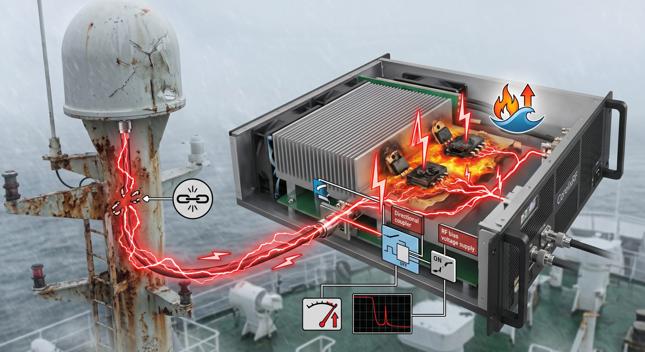
Maritime radar deployments face severe environmental threats globally. Constant exposure toward high salt fog initiates insidious corrosion across RF connectors relentlessly. Such degradation quietly alters antenna impedance over several months continuously. System operators often miss these gradual changes until catastrophic failure occurs unexpectedly. Sudden open circuit conditions force 200 watts of RF energy backward into your transmitter violently. Here is the deal, managing reflected energy backflow requires massive engineering foresight beyond basic heatsinks. Standard components melt within seconds under total mismatch scenarios aboard ships. You need absolute engineering truth regarding physical protection mechanisms during field operations. Deploying resilient hardware prevents devastating operational downtime during vital naval combat missions. CorelixRF designs architecture specifically addressing these brutal field realities explicitly. Our methodology focuses squarely upon ruggedized GaN implementations and strict VSWR monitoring.
1. What Causes Antenna Damage in High Salt Fog Maritime Environments?
Corrosion Mechanics and Impedance Shifts
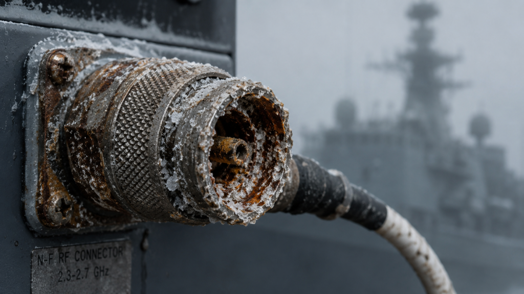
Understanding corrosion mechanics remains fundamental for offshore RF deployments across global naval fleets. High salt fog introduces aggressive chloride ions onto exposed metal surfaces relentlessly. These particles initiate galvanic corrosion across dissimilar metals connecting your vital radiating elements. What’s the real story? Constant mechanical vibration from heavy ship engines accelerates this structural degradation dramatically over time. Antennas operating within 4,000 – 8,000 MHz frequencies demand incredibly precise physical dimensions. Microscopic geometric shifts caused by rust fundamentally alter sensitive feed point impedance profiles entirely. Field technicians frequently observe completely eroded N-F input connectors during routine maintenance checks. Such physical destruction creates an effective open circuit right at your final output stage. Without warning, VSWR spikes exponentially across your entire coaxial transmission line network. An unexpected impedance mismatch instantly blocks forward power transmission toward open air. Consequently, generated RF waves bounce back toward your sensitive amplifier stages aggressively. This phenomenon guarantees hardware destruction unless specific countermeasures exist within your chassis architecture.
Amplifier Frequency and Power Parameters
| Parameter | Specification | Units |
| Frequency Range | 4,000 – 8,000 | MHz |
| Rated Output Power | 200 | W |
| Gain | 55 | dB |
2. How Does Reflected Energy Backflow Trigger Thermal Runaway?
Voltage Standing Wave Physics
Reflected energy backflow creates massive voltage standing wave ratios across compromised transmission lines. When forward waves meet returning reflected waves, they construct localized high-voltage nodes immediately. These massive voltage peaks easily exceed component breakdown thresholds within standard semiconductor packages. This is where it gets interesting… Unmatched 200 W rated output power slamming backward generates immense localized heating. Semiconductor junctions cannot dissipate this sudden thermal load quickly enough through standard heatsinks. Rising temperatures exponentially decrease electron mobility within conventional silicon substrates very rapidly. Decreased efficiency further increases heat generation inside a deadly positive feedback loop scenario. We call this destructive cycle thermal runaway, which destroys active components permanently. A 50 Ω system requires perfect matching for safe electromagnetic energy transfer. Any deviation forces unradiated power into dissipating as pure heat inside your final amplification stage. Field engineers measuring these failures often find completely carbonized transistor packages inside standard chassis designs. Overcoming these physical realities requires deploying specifically engineered RF hardware featuring automated shutdown capabilities.
Input and Output Characteristics
| Characteristic | Value | Unit |
| Input Power | 0 | dBm |
| Input VSWR | 2:1 | Ratio |
| Gain Flatness | ±4 | dB |
3. Why Do Standard Power Amplifiers Fail Under Severe VSWR Conditions?
Transistor Vulnerability and Hardware Limitations
Conventional commercial amplifiers lack adequate isolation against severe mismatch events during offshore operations. Designers often omit robust circulators or precision isolators aiming for cheaper manufacturing costs. Therefore, reflected energy hits delicate output transistors with zero attenuation or impedance buffering. But here’s the kicker Slow protection circuits relying upon simple thermal sensors react far too late. When a thermistor detects dangerous temperatures, catastrophic junction melting has already occurred. Standard equipment simply cannot survive continuous operation under infinite VSWR conditions aboard ships. Maritime applications demand test and measurement grade reliability during vital aviation control operations. Commercial units feature poor gain flatness, fluctuating wildly during rapid environmental impedance shifts. Relying upon standard hardware for electronic warfare or radar jamming guarantees premature mission failure. Engineers must demand equipment featuring integrated, lightning-fast reverse power detection systems natively. Only active monitoring can shut down drive signals before voltage peaks breach maximum transistor limits. Professional integrators always specify purpose-built modules designed specifically for handling hostile field realities.
Interface and Control Specifications
| Feature | Description |
| RF Connectors In/Out | Input: N-F / Output: N-F |
| Control Interface | RS485 / LAN |
| Power Supply | AC 220V±10%, 50/60Hz |
4. How Can Engineers Detect Hidden Open Circuits Using Field Instruments?
Time Domain Reflectometry Applications
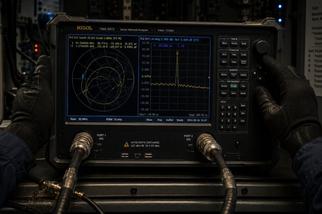
Identifying compromised antenna systems requires specialized diagnostic procedures aboard complex naval vessels. Field technicians must deploy Vector Network Analyzers measuring complex reflection coefficients accurately. You might be wondering… How do we isolate cable faults from actual radome failures? Time Domain Reflectometry pinpoints exact physical locations causing impedance discontinuities along extensive coaxial runs. Sweeping the 4,000 – 8,000 MHz spectrum reveals localized performance collapse clearly. An abnormally high noise floor measured on spectrum analyzers often precedes catastrophic physical breakage. By analyzing complex Smith Chart plots, operators can visualize exact reactance shifts caused by salt accumulation. Routine maintenance must include recording baseline S11 parameters during initial dry-dock installation phases. Comparing current field measurements against these trusted baselines exposes creeping degradation trends early. Proactive diagnostics prevent pushing enormous RF power into a severely compromised radiating load. Such rigorous engineering discipline saves thousands of dollars avoiding emergency replacement hardware costs. CorelixRF encourages implementing strict periodic verification testing across all deployed maritime communication infrastructure.
Protection and Operational Environmental Limits
| Parameter | Specification | Unit |
| Operating Temperature | 0 to 50 | °C |
| Harmonics | -15 | dBc |
| Spurious | -60 | dBc |
5. What Are The Physical Mechanisms Behind GaN Technology Resilience?
Wide Bandgap Semiconductor Advantages
Gallium Nitride substrates offer fundamentally superior material properties for demanding microwave engineering projects. This wide bandgap semiconductor sustains significantly higher electric fields before suffering dielectric breakdown. Consequently, GaN transistors handle massive voltage spikes caused by severe impedance mismatches effortlessly. Let’s dig a little deeper… A design based on advanced GaN technology guarantees exceptional survivability. These modern transistors maintain high efficiency even operating near their absolute maximum thermal limits. Such inherent ruggedness allows our modules surviving conditions destroying conventional LDMOS architectures entirely. Furthermore, GaN provides excellent broad bandwidth capabilities necessary for covering wideband frequency ranges seamlessly. This material enables consistent 55 dB gain across entire specified operational spectrums reliably. When reflected energy surges backward suddenly, GaN devices absorb transient shocks without instantaneous catastrophic failure. Such durability gives active protection circuits vital milliseconds needed for safe automated system shutdown procedures. Implementing advanced semiconductor materials remains critical for maintaining maximum uptime during active naval deployments.
6. How Does The CRF-PA-4000M8000M-200W Handle Infinite VSWR Events?
Automated Shutdown Protocols
CorelixRF engineers engineered this specific amplifier module anticipating worst-case offshore mismatch scenarios explicitly. The rugged CRF-PA-4000M8000M-200W incorporates multi-stage defensive mechanisms against extreme VSWR conditions natively. We implemented a proprietary directional coupler architecture continuously sampling forward and reverse power vectors. Now, observe this specific detail… This unit features built-in protection: over-voltage, over-temperature, over-drive and VSWR protection. When reverse power exceeds predefined safety thresholds, a microcontroller instantaneously cuts necessary RF bias voltages. This action isolates fragile active components from incoming destructive standing waves within bare microseconds. Your entire system gracefully degrades performance rather than failing violently during sudden antenna destruction events. Such engineering truth guarantees your electronic warfare or radar platform remains fundamentally structurally intact. Once maintenance operators repair external cable faults, normal operations resume without requiring internal component replacement. Protecting expensive RF hardware requires implementing uncompromising digital control loops monitoring actual physical realities continuously.
7. Why Is Active Built-in Protection Critical For System Survival?
Digital Telemetry Integration
Passive defensive measures alone cannot secure high-power microwave transmission systems reliably during combat. Purely analog matching networks provide narrow-band protection, failing across multi-octave operating bandwidths completely. Therefore, active digital telemetry monitoring remains an absolute requirement for robust naval hardware deployments. Here is a pro tip System integrators must utilize provided control interfaces, specifically RS485 / LAN connections natively. These digital communication protocols allow continuous polling regarding critical internal amplifier health metrics. If localized heating triggers thermal alarms, host controllers can intelligently reduce RF drive power levels. Such coordinated responses prevent hard shutdowns during vital test & measurement or aviation control missions. Customizable alarm thresholds give radar operators precise control over automated safety reactions globally. CorelixRF prioritizes complete diagnostic visibility, ending an era of blind high-power hardware operation. This methodology transforms raw power amplifiers into highly intelligent nodes within modern electronic warfare networks. Building intelligent arrays prevents isolated component failures from cascading across your whole RF infrastructure.
8. How Do We Implement Proper Heat Dissipation In A 4U Chassis?
Forced Air Dissipation Strategies
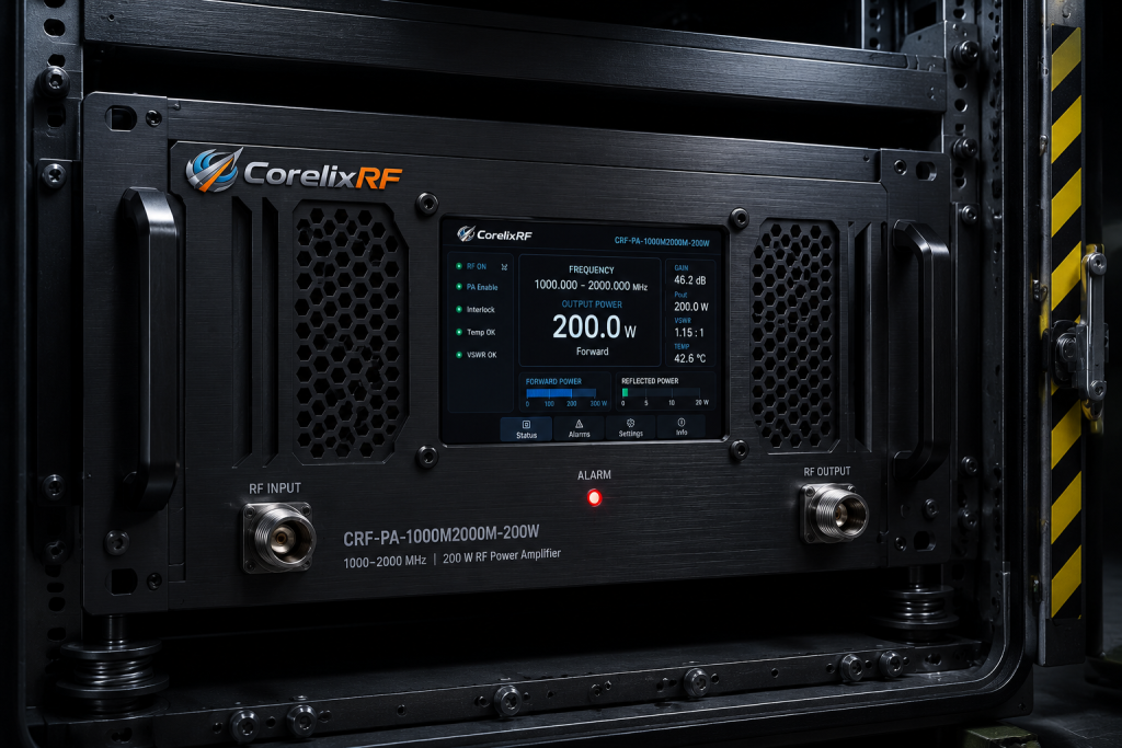
Managing tremendous amounts of continuous RF output demands massive thermal dissipation capabilities constantly. Every watt of electrical inefficiency converts directly into destructive heat trapped inside sealed equipment racks. Our mechanical design team specifically selected a standardized 4U package size for maximum airflow. This specific dimension allows routing cooling channels past massive internal aluminum heatsink fins efficiently. Here is amazing news We utilize a highly effective forced air cooling method guaranteeing continuous thermal extraction. High-CFM industrial fans pull ambient air across critical semiconductor junctions aggressively without pause. This robust mechanical architecture guarantees remarkably stable performance across operating temperatures ranging from 0 to 50 °C. Complete outline drawings provide clear integration reference for mechanical engineers designing sealed shipboard cabinets. Proper thermal management prevents premature component aging, drastically extending your total system lifecycle significantly. Maintaining cool transistor operating temperatures represents fundamental engineering truth for high-power microwave hardware design.
Mechanical and Environmental Data
| Component | Details | Standard |
| Package Size | 4U | Dimensions |
| Cooling Method | Forced air cooling | Architecture |
| Compliance | RoHS Compliant / CE / FCC | Quality |
9. What Are The Key Installation Practices For Marine RF Hardware?
Marine Deployment Specifications
Deploying heavy industrial electronics at sea requires strict adherence toward professional mounting procedures consistently. Racks endure constant low-frequency mechanical pounding from massive diesel propulsion systems continuously. Technicians must utilize heavy-duty shock absorbers when installing standard 19-inch enclosures aboard vessels. Truth be told Ensuring proper torque on all RF Connectors In/Out, specifically Input: N-F Output: N-F, prevents intermittent contact completely. Loose connections generate massive passive intermodulation, polluting surrounding communication spectrums entirely with destructive noise. Power supply connections demand marine-grade shielding, delivering incredibly clean AC 220V±10%, 50/60Hz under fluctuating generator loads. We recommend applying specialized dielectric grease across all exterior coaxial mating surfaces during final installation. This precaution prevents microscopic salt crystals from penetrating threaded interfaces and degrading vital return loss. Such meticulous physical installation practices form a critical foundation for long-term offshore operational success. Shortcuts taken during physical deployment inevitably cause massive hardware failures during severe oceanic storms.
10. How Can Integration Teams Validate System Reliability Before Deployment?
Laboratory Verification Procedures
Pre-deployment verification separates professional engineering from dangerous guesswork regarding expensive military hardware. Integrators must subject fully assembled cabinets against rigorous simulated environmental extremes thoroughly. Injecting calculated impedance mismatches verifies automatic VSWR protection triggering under strictly controlled laboratory conditions. Ready for the good part? Test data and pattern files can be supplied for project review where applicable. Engineers must verify overall spectral purity, verifying harmonics remain strictly below -15 dBc continuously. Likewise, potentially disruptive spurious emissions must never exceed -60 dBc during maximum power output testing. All critical baseline measurements require strict adherence regarding test conditions: 50Ω system, unless otherwise specified. Documenting these vital parameters provides an invaluable reference point for future complex offshore troubleshooting efforts. CorelixRF guarantees hardware compliance through strict quality frameworks, adhering toward CE / FCC and ISO 9001 standards. Thorough validation testing prevents deploying compromised equipment into highly dangerous maritime operational theaters.
Deploying heavy hardware within severe maritime environments demands absolute physical truth explicitly. Accidental antenna degradation causes lethal reflected energy backflow, instantly destroying poorly protected standard electronics. Deploying a rugged CRF-PA-4000M8000M-200W guarantees vital mission continuity despite sudden catastrophic radome failures. System integrators must adopt resilient GaN architecture featuring automated active mismatch protection protocols entirely. Contact CorelixRF engineers today regarding customized RF power solutions protecting your crucial offshore communication platforms. Implementing strict quality frameworks guarantees your radar systems remain operational during combat deployments. We stand ready for assisting your engineering team with complex integration challenges across hostile global operational theaters. Investing in purpose-built microwave amplification equipment prevents disastrous system outages when oceanic conditions deteriorate rapidly.
- Q1: What is reflected energy backflow?
- Reflected energy backflow occurs whenever an impedance mismatch exists between a transmitter and its corresponding radiating element. Normally, RF power flows smoothly toward a perfectly tuned 50-ohm load. However, physical damage causes sudden impedance shifts, preventing effective forward propagation entirely. Consequently, unradiated electromagnetic waves reverse direction, traveling backward down your coaxial transmission line. These returning waves collide with incoming forward signals, creating massive standing voltage peaks. High-power systems pushing 200W output will experience catastrophic transistor failure during such events. Semiconductors cannot dissipate this trapped energy, leading directly toward rapid thermal runaway. CorelixRF mitigates this risk by designing custom directional couplers capable of sensing reverse surges. Our hardware instantly drops bias voltages before junction temperatures reach critical melting thresholds. Such proactive defense mechanisms represent fundamental engineering truth for professional naval system integrators.
- Q2: How does VSWR protection work?
- Built-in VSWR protection operates as an automated emergency shutdown mechanism guarding against sudden mismatch events. Engineers deploy precision directional couplers sampling continuous forward and reverse power vectors simultaneously. A fast-acting microcontroller analyzes these analog voltage ratios against strict pre-programmed safety thresholds continuously. This is where it gets interesting… When reflected power indicates dangerous open circuit conditions, analog switches isolate sensitive active components instantaneously. The protection system features built-in capabilities: over-voltage, over-temperature, over-drive and VSWR protection. This multi-layered defense prevents localized hot spots from destroying expensive GaN semiconductor junctions. Normal operations resume automatically once field technicians resolve external cable faults or replace broken antennas. Implementing active digital control loops saves thousands of dollars avoiding unnecessary hardware replacement. System operators monitor these vital safety triggers via RS485 / LAN interfaces directly.
- Q3: Why do high salt fog environments destroy marine antennas?
- Marine environments present exceptionally hostile conditions attacking exposed electronic infrastructure continuously without mercy. High salt fog carries corrosive chloride compounds directly onto delicate metallic connector interfaces. These microscopic particles bypass inadequate weatherproofing seals, initiating rapid galvanic corrosion across dissimilar metal joints. Over several months, this chemical degradation alters critical physical dimensions required for proper tuning. Connectors such as Input: N-F Output: N-F suffer severe material loss under constant maritime exposure. Eventually, heavily corroded mating surfaces lose electrical continuity, creating a sudden open circuit. Furthermore, intense structural vibrations generated by massive ship engines accelerate mechanical fatigue failure exponentially. Such combined environmental assaults guarantee eventual transmission line failure, demanding incredibly robust amplification equipment. Commercial grade hardware simply perishes quickly under these unrelenting oceanic assault conditions. Professional naval integrators must demand equipment specifically rated for punishing offshore deployment scenarios.
- Q4: What makes GaN technology superior for rugged hardware?
- Gallium Nitride represents a massive evolutionary leap forward regarding high-power semiconductor material science. This wide bandgap material sustains significantly higher internal electric fields before suffering catastrophic dielectric breakdown. Consequently, GaN transistors handle immense voltage spikes generated during severe standing wave events effortlessly. Designers specify this substrate specifically because it maintains exceptional efficiency near extreme thermal limits. A design based on advanced GaN technology guarantees incredible survivability during combat scenarios. Traditional silicon-based components suffer rapid mobility collapse when subjected toward similar overheating stress. GaN additionally provides superb broad bandwidth characteristics, easily covering 4,000 – 8,000 MHz seamlessly. Such ruggedness buys active protection circuits vital milliseconds required for safely shutting down operations. Investing in modern semiconductor architecture eliminates frequent maintenance cycles plaguing older LDMOS installations. Engineering truth dictates using optimal materials for resolving incredibly tough physical challenges globally.
- Q5: How can field technicians identify hidden transmission line faults?
- Diagnosing hidden RF transmission issues requires deploying sophisticated laboratory-grade test instruments aboard naval vessels. Field engineers utilize Vector Network Analyzers measuring complex reflection coefficients across broad frequency spectrums. Time Domain Reflectometry sweeps pinpoint precise physical distances where catastrophic cable faults exist. Monitoring performance via spectrum analyzers reveals abnormally high noise floors preceding total hardware collapse. Maintaining meticulous records regarding baseline S11 parameters during initial dry-dock installation remains absolutely critical. Technicians compare current real-world measurements against these original baselines, exposing creeping degradation trends early. Identifying a failing antenna prevents pushing massive RF power into a severely compromised load. Testing requires strict adherence toward professional procedures utilizing a properly calibrated 50Ω system. Proactive diagnostic schedules prevent surprise system outages during vital maritime navigation or radar missions. CorelixRF supports integrators by providing detailed troubleshooting documentation for complex offshore installations.