
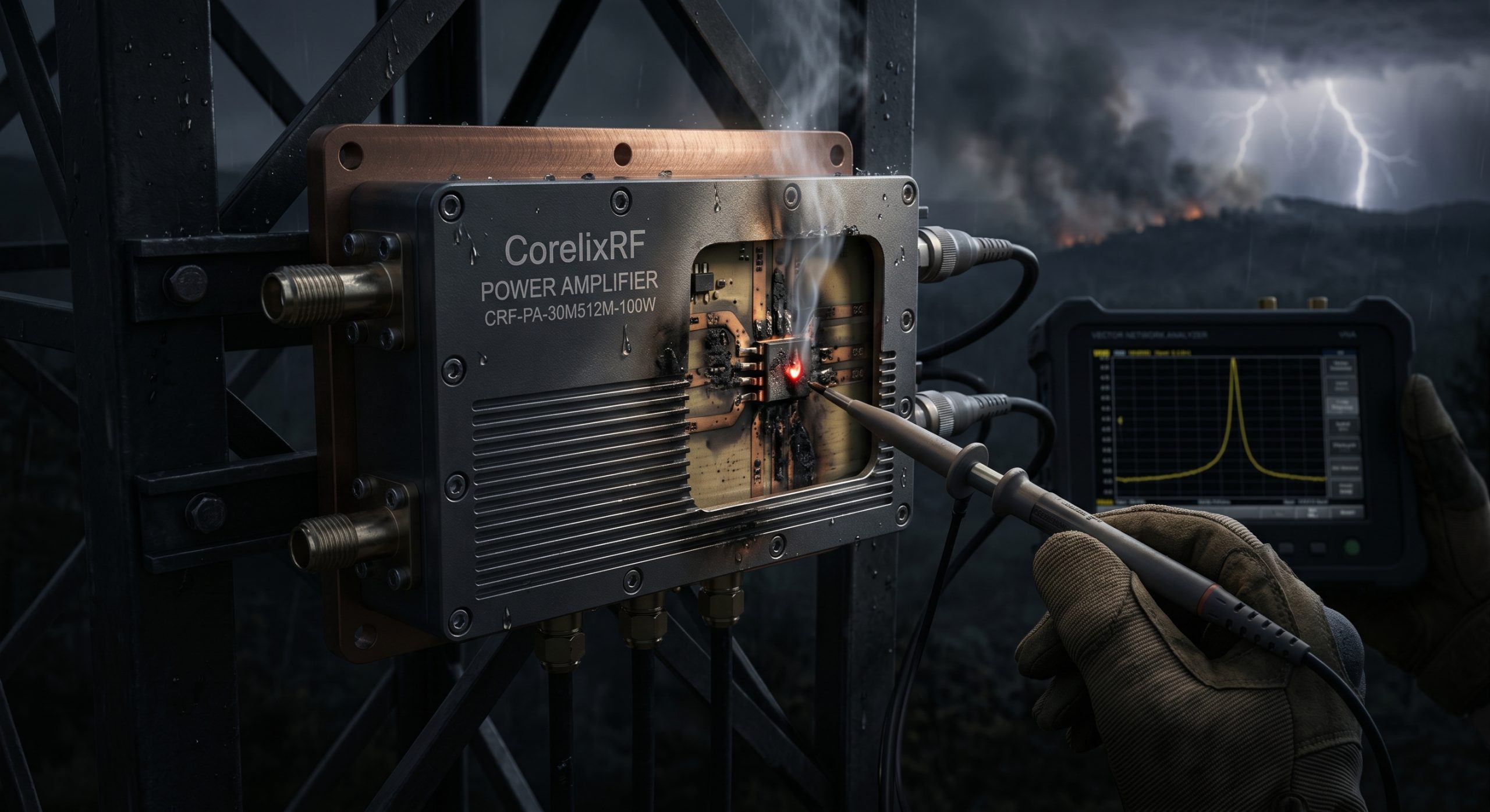
1. What causes antenna damage in harsh fire monitoring environments?
Wildfire observation towers sit atop exposed ridge lines facing brutal weather extremes continuously. High winds routinely snap rigid mast structures outright without advanced warning. Heavy smoke particulate accumulation degrades exterior radome materials rapidly over several months. Wildlife interference often compromises exposed coaxial cable runs causing dangerous micro-fractures. Here is the kicker: these structural failures happen unpredictably far away from accessible maintenance depots. Ground shifts near active burn zones misalign directional arrays completely destroying targeted coverage. Connectors experience massive thermal cycling shifting between freezing nights and blistering afternoon heat. Such dramatic temperature swings loosen threaded couplings incrementally until complete physical separation occurs. Moisture ingresses past compromised O-rings altering dielectric constants permanently inside critical feedlines. Operators notice sudden signal drops indicating severely degraded integrity across remote telemetry dashboards. Complete open circuits result inevitably from unmitigated mechanical stress over extended deployment periods.
Structural Hazard Analysis
| Failure Mode | Physical Cause | RF Consequence |
| Mast Snapping | High velocity wind shear | Instantaneous open circuit |
| Connector Loosening | Extreme thermal cycling | Intermittent impedance mismatch |
| Cable Micro-fractures | Wildlife or falling debris | Gradual VSWR degradation |
2. How does an open circuit trigger reflected energy reverse flow?
RF physics dictates absolute necessity regarding impedance matching across entire transmission paths. A severed antenna cable presents infinite impedance terminating any forward propagating waves instantly. Forward traveling electromagnetic energy hitting this boundary cannot radiate outward into open space. You might be wondering: where exactly does that unradiated power go? Physics demands conservation meaning those watts bounce backward toward your signal source. This returning wave collides violently with incoming forward signals generating destructive standing waves. Voltage maximums multiply along transmission lines exceeding component breakdown ratings almost immediately. Engineers measure this phenomenon using Voltage Standing Wave Ratio metrics during diagnostic testing. A perfect match yields 1.0:1 but severed cables spike this metric toward infinity. Reflected power dumps raw kinetic energy directly back into fragile final stage transistors. Unprotected semiconductor junctions melt under such massive reverse voltage spikes without warning.
3. Why do traditional RF systems experience thermal runaway during VSWR faults?
Generic transmission gear lacks sufficient isolator protection against massive reverse power surges. Standard gallium arsenide devices process forward amplification efficiently but fail handling backward reflections. Returning energy dissipates entirely as pure heat inside poorly designed transistor packaging. What is the real story? Baseplate cooling systems cannot sink this sudden localized thermal explosion fast enough. Junction temperatures spike beyond maximum theoretical limits destroying atomic lattice structures permanently. Our factory engineers possessing 30 years manufacturing experience document these failures frequently. We observe charred PCB traces surrounding melted final stage amplifying components regularly. Thermal runaway creates a cascading failure loop drawing excessive current from system power supplies. More current generates even higher heat accelerating total catastrophic hardware destruction exponentially. Inadequate thermal mass under active devices guarantees rapid failure during severe mismatch events. Surviving such conditions requires intentional robust engineering focused upon thermal dissipation realities.
Reflection Mechanics
| VSWR Level | Return Loss | Reflected Power Percentage |
| 1.5:1 | 14 dB | 4.0% |
| 2.0:1 | 9.5 dB | 11.1% |
| Infinite | 0 dB | 100% |
4. How can engineers detect hidden RF failures using field diagnostic tools?
Frontline technicians utilize specialized field gear diagnosing complex remote transmission issues accurately. Portable vector network analyzers provide immediate visual confirmation regarding antenna resonance shifts. Sweeping across designated bands reveals sudden impedance changes indicating water ingress problems. Time Domain Reflectometry pinpoints exact physical distance measurements locating hidden cable cuts accurately. This is where it gets interesting: measuring equipment highlights microscopic faults before complete system failure. Inserting directional couplers inline allows simultaneous forward and reverse power monitoring continuously. Technicians viewing oscilloscope traces identify clipping waveforms proving amplifier saturation under mismatched loads. Checking baseline noise floor figures confirms whether external interference degrades receiver sensitivity artificially. Deploying rugged test instruments validates actual field conditions against factory benchmark data. Rigorous troubleshooting demands hard numbers rather than guessing about potential failure origins. Proper instrumentation reveals Engineering Truth exposing poorly constructed components failing under pressure.
5. What specific symptoms indicate catastrophic power amplifier stress?
Monitoring baseline telemetry provides early warning signs predicting imminent hardware destruction events. A healthy transmitter draws stable current directly proportional toward rated output levels. Sudden unexpected DC current spikes indicate severe output mismatch forcing transistors into stress. Ready for the good part? Smart monitoring dashboards flag these anomalous power consumption metrics immediately. Another massive red flag involves severe gain compression resulting in degraded transmission range. Field agents report dropping audio frames or corrupted data packets during active deployments. Spectrum analyzers reveal elevated harmonic distortion exceeding standard regulatory compliance limits significantly. Operating under extreme mismatch forces amplifiers into non-linear regions generating unwanted spurious emissions. Equipment housings become dangerously hot touching them physically burns unprotected skin surfaces quickly. These distinct physical symptoms confirm catastrophic reverse power flow damaging internal RF circuitry. Recognizing such warning signs prevents complete station burnout saving expensive replacement costs entirely.
Hardware Stress Indicators
| Diagnostic Metric | Normal Operation | Critical Fault Condition |
| DC Current | Stable | Sudden massive spike |
| Baseplate Temp | Warm | Dangerously hot |
| Signal Quality | Clean | Severe packet loss |
6. How does the CRF-PA-30M512M-100W address high VSWR conditions physically?
Our 400 employees manufacture robust solutions battling these exact remote deployment nightmares. The CRF-PA-30M512M-100W amplifier model incorporates aggressive protection circuits surviving terrible field conditions. This specific unit handles an output VSWR reaching 2.0:1 safely without performance degradation. Internal architecture utilizes rugged LDMOS transistors withstanding severe impedance mismatches indefinitely. Truth be told: survival requires massive copper-coin integration directly beneath active power devices. Heat spreads laterally pulling thermal energy away from delicate semiconductor junctions rapidly. A rated output delivering 100 W continuous wave demands absolute thermal stability consistently. Input drive parameters require merely 0 dBm pushing full saturation efficiently. Built-in current limiting prevents runaway consumption capping maximum draw at $\le18$ A strictly. These engineered safeguards guarantee operational continuity even when external antennas suffer damage.
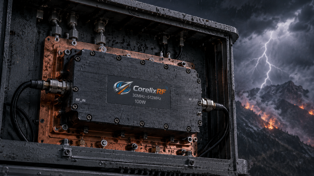
CRF-PA-30M512M-100W Core Parameters
| Parameter | Specification | Unit |
| Rated Output | 100 | W |
| Supply Voltage | 28 | VDC |
| Max Current | 18 | A |
| Output VSWR | 2.0:1 | Ratio |
7. What role does rugged mechanical design play in preventing thermal degradation?
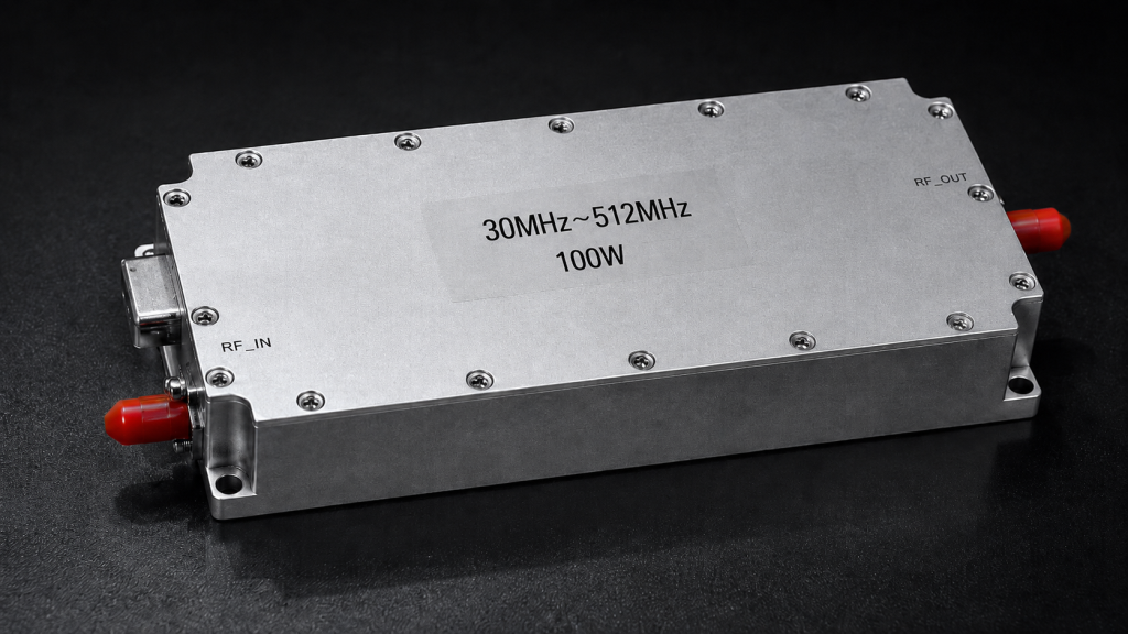
Physical construction dictates long term survival probability within brutal outdoor installation environments. The CRF-PA-30M512M-100W features compact dimensions measuring exactly 200\times158\times25~mm saving rack space. Machined aluminum alloy housings provide immense structural rigidity shielding internal microwave boards. Weighing only 1.4 kg simplifies hauling equipment up steep remote mountain trails. Let that sink in for a moment: lightweight designs reduce structural strain across remote tower racks significantly. Effective air cooling mechanisms dissipate internal heat maintaining safe operating margins continuously. Operating temperatures spanning -40 up through +85 °C cover extreme environmental swings effortlessly. High quality N-Female RF output connectors ensure reliable tight mechanical mating strictly. Input connections utilize standard SMA-Female ports guaranteeing compatibility across diverse integration setups. Proper mechanical grounding prevents stray RF currents from causing unpredictable digital logic faults.
8. How do wideband frequency characteristics impact remote communication stability?
Wildfire emergency teams rely upon frequency agility bypassing crowded or jammed channels. Spanning a massive 30-512 MHz spectrum allows seamless hopping across VHF/UHF bands. Maintaining consistent performance across this entire range requires precise impedance matching networks. Gain levels holding steady at 50 dB deliver massive signal boosting capability reliably. Think about that: massive broadband coverage eliminates carrying multiple narrow band amplifier units. Exceptional gain flatness remaining 1.8 dB ensures uniform power delivery everywhere. Engineers appreciate this linear response simplifying complex system level link budget calculations. Input VSWR figures staying below 1.8:1 prevent driving exciters into unstable states. Consistent RF performance across wide spectrums guarantees reliable voice and data transmission. Fire crews coordinate tactical movements confidently knowing communication links remain rock solid.
Frequency Performance Data
| RF Metric | Value | Reference |
| Bandwidth | 30-512 MHz | |
| Nominal Gain | 50 dB | |
| Gain Flatness | $\le1.8$ dB |
9. Why are strict electrical parameters critical for sustained field operations?
Unpredictable remote environments demand absolute electrical stability preventing sudden cascading subsystem failures. Operating via standard 28 VDC supply lines aligns perfectly alongside common backup batteries. Suppressing unwanted signals keeps designated transmission frequencies clean avoiding adjacent channel interference. Harmonics remain strictly suppressed measuring -10 dBc mitigating regulatory compliance violations effectively. But wait, there is more: keeping spurious emissions below -60 dBc proves exceptional spectral purity. Clean spectrum outputs prevent jamming nearby collocated receiver equipment accidentally during operations. Reliable saturated CW power output formats support continuous high duty cycle demands. Our engineering team guarantees these parameters through rigorous automated factory testing protocols. Every unit departing our facility meets exacting specifications ensuring flawless frontline performance. System integrators trust these verified numbers when designing mission critical monitoring networks.
10. How should integration teams optimize preventative maintenance protocols?
Proactive maintenance strategies extend expensive hardware lifespans significantly across harsh outdoor deployments. Field crews must schedule routine coaxial cable inspections identifying minor jacket abrasions early. Deploying automated VSWR alarm thresholds alerts centralized dispatch centers regarding developing faults. Bottom line: catching degrading antenna matches early saves amplifiers from enduring catastrophic stress. Technicians should re-torque all exposed N-Type connectors using calibrated tools semiannually. Waterproofing vulnerable junctions using specialized self-amalgamating tape prevents disastrous moisture ingress issues. Analyzing historical telemetry data helps predict seasonal failure trends allowing preemptive component replacement. Upgrading legacy sites using ruggedized CorelixRF equipment establishes reliable long term operational baselines. Implementing strict diagnostic sweeping procedures confirms total system health following severe weather events. True Engineering Truth relies upon verified data rather than hopeful assumption models.
Conclusion
Wildfire monitoring demands uncompromising RF hardware capable of surviving severe operational realities continuously. Mitigating reflected power damage requires deploying intelligently engineered amplifiers possessing massive thermal resilience. We strongly recommend evaluating current system vulnerabilities against true physical environmental threats. System architects facing harsh deployments should consult our factory direct engineering resources today. Upgrading existing infrastructure utilizing proven robust components prevents disastrous communication blackouts effectively.
FAQ
Q1: What causes antenna damage in harsh fire monitoring environments?
High winds snap masts while thermal cycling loosens connectors causing massive physical separation.
Q2: How does an open circuit trigger reflected energy reverse flow?
Severed cables present infinite impedance reflecting forward traveling electromagnetic waves backward instantly.
Q3: Why do traditional RF systems experience thermal runaway during VSWR faults?
Reflected energy converts into heat destroying delicate semiconductor junctions lacking proper thermal dissipation.
Q4: How can engineers detect hidden RF failures using field diagnostic tools?
Technicians utilize vector network analyzers measuring impedance shifts alongside time domain reflectometers locating cuts.
Q5: What specific symptoms indicate catastrophic power amplifier stress?
Sudden severe DC current spikes and dangerously hot equipment housings confirm catastrophic internal stress.
Review the amplifier, antenna and VSWR path together
High VSWR protection depends on the amplifier, antenna, cable loss and mismatch scenario. Send the expected load condition, protection threshold, recovery behavior, alarm output and required FAT evidence before selecting hardware.
Recommended next step: send the operating band, target output power, duty cycle, thermal or load condition, control interface, protection behavior and required FAT documents. CorelixRF can review this telemetry link high VSWR RF amplifier deployment requirement against standard amplifier platforms, RF front-end options and custom engineering constraints.