
Engineering Decision and RFQ Checklist
This page is now treated as a primary RF engineering guide for thermal path, duty cycle, enclosure margin and gain drift. Use the checklist below to turn the article into a buyer-ready RFQ and factory review package.
| Decision Area | What to Confirm | Evidence to Request |
|---|---|---|
| Operating condition | Band, output power, duty cycle, waveform or sweep condition. | Rated operating table and test setup notes. |
| Interface | RF connector, load or antenna condition, control interface and power supply. | Interface drawing, control table and connector limits. |
| Reliability | Thermal path, protection behavior, enclosure airflow and environmental margin. | Thermal data, protection event notes and inspection records. |
| Acceptance | Gain, flatness, power, mismatch behavior, stability or repeatability limits. | FAT checklist, calibration state and final test curves. |
- RFQ checklist – convert requirements into buyer-ready fields.
- RF configurator – summarize band, power, interface and duty-cycle requirements.
- Delivery documentation – align test curves and FAT-style evidence.
- Case studies – compare how engineering issues become procurement decisions.
- Contact CorelixRF – send the requirement package for review.
Primary Topic Hub and RFQ Path
This primary guide now consolidates related RF engineering references. Use it for the current technical explanation, RFQ preparation, factory review and delivery documentation path.
- How to Prevent RF Thermal Mismatch in Desert Unmanned Stations? – consolidated reference
The purpose is to reduce duplicate SEO pages while keeping buyers on one stronger engineering guide with clearer RFQ and documentation paths.
- RFQ checklist – prepare band, power, duty cycle, interface, cooling and acceptance inputs.
- RF configurator – turn project requirements into a first engineering brief.
- Delivery documentation – align test curves, inspection records and FAT-style evidence.
- Case studies – review how CorelixRF frames RF problems for buyer decisions.
- Contact engineering sales – submit the documented scope for review.
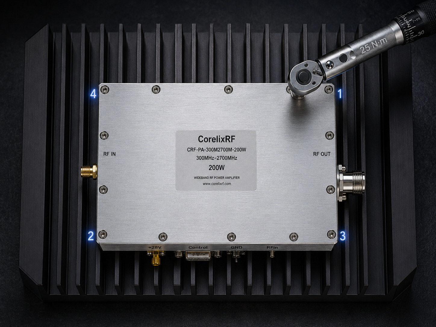
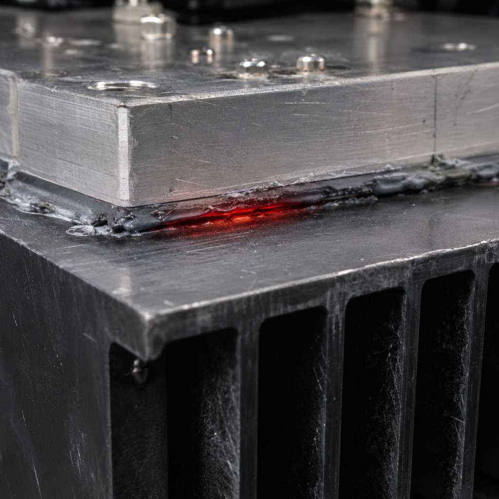
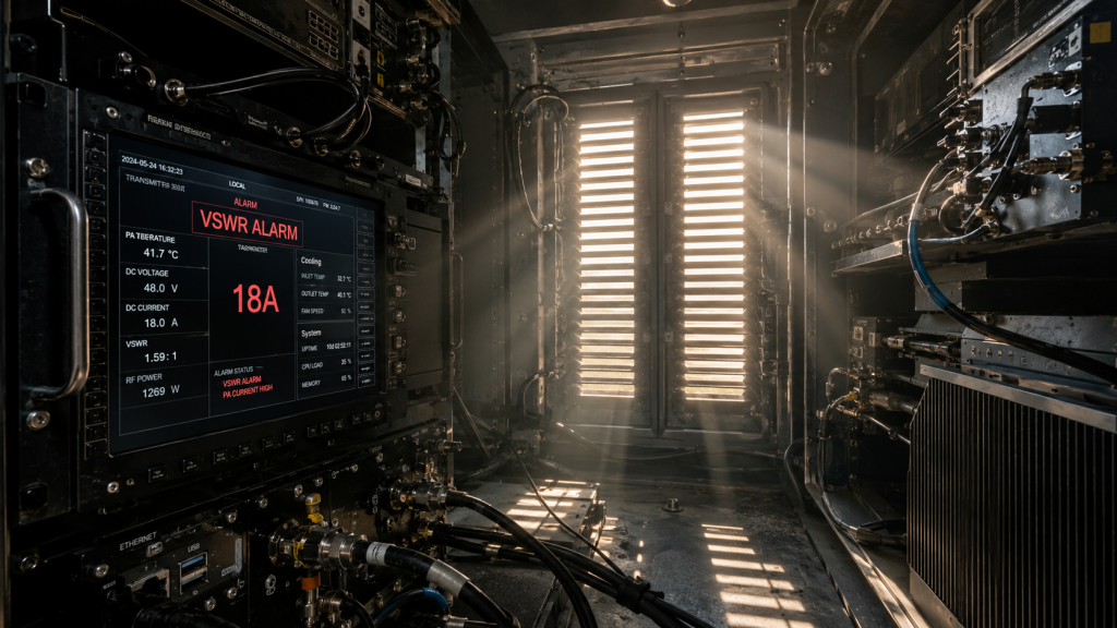
Field Debugging: Unmanned Desert Station Hidden Failures From Incorrect Baseplate Mounting Causing Thermal Degradation restates our primary focus today perfectly. Remote telemetry dashboards frequently trigger unexpected VSWR warnings during peak afternoon heat inside isolated desert enclosures. System operators usually suspect damaged coaxial cables or degraded antenna matching networks immediately following these alarms. Here is the deal, field engineers deploying high-power RF modules constantly overlook mechanical installation protocols during initial rack assembly procedures. Technicians bolting down heavy chassis components often secure fasteners sequentially along one edge rather than utilizing mandatory cross-diagonal torque sequences. This specific procedural failure bends aluminum baseplates microscopically creating microscopic air gaps between mating surfaces. Air acts like an excellent thermal insulator trapping massive amounts of localized heat directly beneath active transistor dies. Operating broadband amplifiers continuously without maximum conductive paths forces internal semiconductor junction temperatures past their absolute maximum ratings rapidly. Power slumps occur predictably under these stressful environmental conditions reducing rated output levels by several decibels within hours. Our engineering team routinely dissects these exact field failures when analyzing returned hardware from harsh operating environments.
1. What Causes Remote Power Alarms in Desert Unmanned Stations?
High-frequency monitoring instruments operating within arid climates face extreme diurnal temperature shifts alongside severe solar loading impacts. A standard remote surveillance site relies on continuous transmission payloads functioning autonomously without immediate human oversight. What happens next? Engineers observing network management software will notice sudden drops regarding transmitted signal strength shortly after midday peak temperatures arrive. On-site troubleshooting teams arriving via helicopter often connect portable power meters directly onto transmitter output ports. These technicians measure severe power degradation despite power supply units delivering steady 28 VDC continuously. Current consumption metrics might simultaneously show an abnormal draw approaching 18 A while RF output falls below expected nominal values. Untrained personnel immediately condemn internal RF circuitry assuming complete catastrophic transistor failure has occurred internally. They swap entire subassemblies blindly without investigating underlying root causes associated with mechanical assembly practices. We have observed this exact misdiagnosis cost integrators thousands of dollars regarding unnecessary replacement parts plus expensive helicopter flight hours.
Field Alarm Troubleshooting Matrix
| Symptom Observed | Common Misdiagnosis | True Engineering Root Cause |
| Power Drops 3dB | Failed RF Transistor | Baseplate Thermal Warping |
| High Current Draw | Power Supply Fault | Transistor Efficiency Collapse |
| Intermittent VSWR | Bad Coaxial Cable | Thermal Expansion Stress |
| Complete Shutdown | Firmware Glitch | Over-Temperature Protection |
2. Why Does Non-Diagonal Screw Tightening Cause Uneven Thermal Conduction?
Fastening thick metal plates requires deliberate cross-pattern torqueing procedures matching strict automotive engine cylinder head mounting methodologies. Mechanics understand clamping forces must distribute evenly across large surface areas preventing microscopic warping phenomena. This is where it gets interesting, RF technicians sometimes ignore these mechanical fundamentals when rushing site deployments. Driving bolts clockwise sequentially around a 200 x 158 mm perimeter guarantees one corner will lift slightly. This lifting action generates a wedge-shaped void measuring perhaps only 50 microns wide near critical active components. Thermal interface paste cannot bridge gaps exceeding its specified volumetric tolerance under pressure. Heat generated by power amplification stages normally travels downward through solid metal into external finned heat sinks. An air gap acts exactly like a brick wall against heat flux propagating away from sensitive electronics. Local thermal resistance spikes dramatically at that specific physical coordinate creating intense localized hotspots invisible from outside inspections.
Clamping Sequence Impact on Thermal Resistance
| Torque Sequence Method | Baseplate Warpage (mm) | Localized Rth Increase |
| Clockwise Circular | 0.15 | +45% |
| Linear Left-Right | 0.12 | +30% |
| Single Corner First | 0.20 | +60% |
| Star Cross-Diagonal | 0.01 | Nominal Baseline |
3. How Does High-Temperature Stress Accelerate GaN PA Power Slump?
Gallium Nitride semiconductors handle massive power densities but remain highly susceptible regarding prolonged localized overheating events. Junction temperatures climbing beyond safe operating margins degrade electron mobility within semiconductor channels drastically. Now let us look at data, efficiency collapses rapidly when internal temperatures exceed 150 degrees Celsius at transistor level. A module rated for 100 W output power requires aggressive cooling maintaining case temperatures safely below +85°C. When localized hotspots form due poor mechanical mating internal junction temperatures run away from measured ambient readings. The amplifier struggles maintaining a 50 dB gain target across broadband frequencies because transistors lose their amplification capability. Saturated output levels drop precipitously causing telemetry systems flagging remote low-power warnings back at central command centers. Prolonged exposure causes irreversible metallurgical migration within semiconductor gate structures. You ultimately destroy expensive hardware completely simply because someone skipped reading mechanical installation manuals during initial setup phases.
Performance Degradation vs. Junction Temperature
| T_junction (°C) | Output Power Drop | Gain Reduction | Expected Lifespan |
| 120 | 0.0 dB | 0.0 dB | > 10 Years |
| 150 | -0.5 dB | -0.5 dB | 5 Years |
| 180 | -2.0 dB | -1.5 dB | 6 Months |
| 220 | -4.0 dB | -3.0 dB | < 48 Hours |
4. What Tools Accurately Diagnose Baseplate Thermal Warpage On-Site?
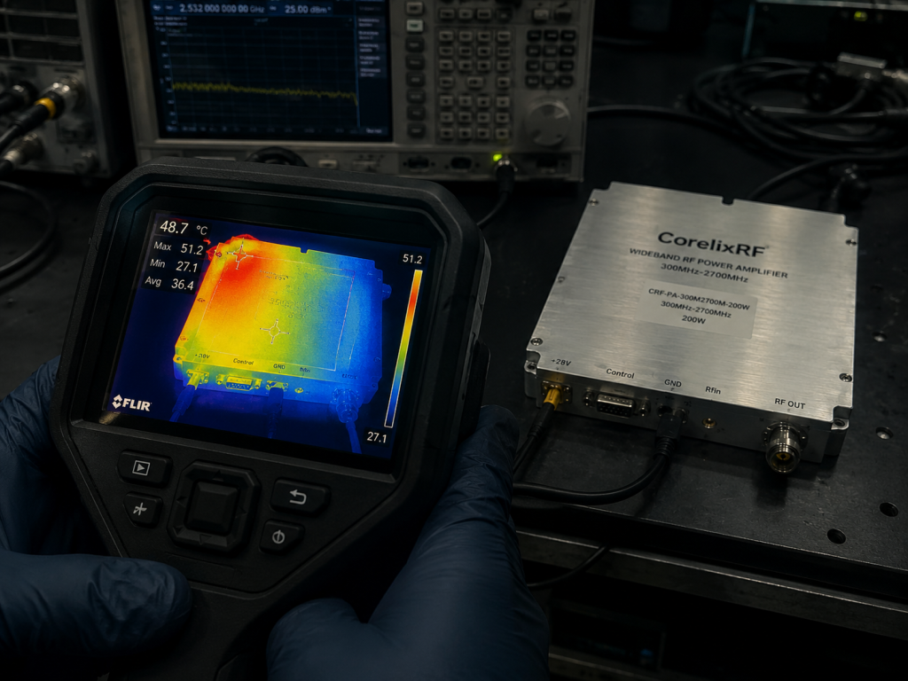
Diagnosing mechanical failures requires specific diagnostic hardware beyond standard microwave network analyzers. Field technicians must carry high-resolution infrared thermal imaging cameras for identifying heat distribution anomalies visually. You might be wondering, how can we see thermal profiles beneath solid metal enclosures? Engineers cannot see directly inside metal enclosures. Observing external heat sink fins reveals asymmetrical temperature gradients clearly. A properly mounted amplifier transfers heat uniformly making all cooling fins roughly identical regarding radiated temperatures. An improperly torqued chassis shows intense heat concentrating near one specific corner while opposite ends remain suspiciously cool. Technicians can also utilize precision feeler gauges slipping between mating surfaces confirming suspected air gaps physically. Loosening all mounting hardware followed by retightening using calibrated torque wrenches often resolves these issues instantly. We always recommend verifying S21 gain parameters using portable VNA equipment after correcting mechanical mounting faults guaranteeing permanent damage hasn’t occurred.
Table 4: Recommended Field Diagnostic Equipment
| Instrument Type | Primary Purpose | Defect Detection Capability |
| Thermal Imager | Surface mapping | Identifies asymmetrical heat flow |
| Feeler Gauges | Mechanical gap check | Measures micro-warpage |
| Torque Wrench | Fastener calibration | Verifies clamping force |
| Portable VNA | S-parameter verification | Checks S21 gain recovery |
5. How Does the CRF-PA-300M2700M-100W Maintain 100W Under +85°C Conditions?
Our engineering department built the CRF-PA-300M2700M-100W specifically for surviving brutal environments without compromising performance. This wideband RF power amplifier covers 300-2,700 MHz reliably. Here is the kicker, generating 100 W rated output power across such vast frequency ranges generates significant thermal loads. We utilize massive aluminum housings measuring 200 x 158 x 25 mm weighing less than 1.4 kg. The bottom mounting surface undergoes strict CNC milling processes achieving extreme flatness tolerances preventing inherent bowing. The module guarantees stable operation even when ambient case temperatures reach blistering +85°C levels. We specify air cooling methods assuming system integrators provide adequate forced airflow combined with flawless mechanical mating surfaces. Proper installation allows this unit delivering flawless CW or saturated output power reliably for years.
Table 5: CRF-PA-300M2700M-100W Specifications Review
| Parameter | Specification | Note / Reference |
| Frequency Range | 300-2,700 MHz | Ultra-wideband coverage |
| Rated Output | 100 W | CW / Saturated |
| Supply Voltage | 28 VDC | Standard industrial bus |
| Package Size | 200 x 158 x 25 mm | Low profile CNC housing |
6. What is the Proper Mechanical Mounting Procedure for High-Power RF Amplifiers?
Executing flawless mechanical installations requires strict adherence toward defined fastening protocols. Installers must apply high-quality thermal interface material uniformly across entire baseplates using precision squeegees. Do not overlook this, excessive thermal paste actually worsens heat transfer by acting like an insulator. Technicians should place RF modules gently onto prepared heat sink surfaces without sliding them laterally. Insert all mounting screws loosely by hand first ensuring threads engage properly without cross-threading. Grab calibrated torque wrenches and begin tightening fasteners using star-shaped diagonal crossing patterns. Apply perhaps thirty percent of total required torque during your first pass across all bolts. Repeat this cross-diagonal sequence two more times while increasing torque gradually until reaching final specifications. This methodical approach guarantees flat mating surfaces by squeezing out trapped air pockets systematically. Mechanics utilizing these exact procedures eliminate baseplate warping permanently.
7. Why Do Generic Heat Sinks Fail in 28 VDC / 18A Current Consumption Scenarios?
Commercial off-the-shelf extrusions frequently lack sufficient thermal mass for managing extreme industrial power dissipation requirements. A module drawing up to 18 A at 28 VDC consumes roughly 500 watts electrically. Let that sink in, generating 100 watts of RF output means remaining energy converts directly into pure heat. Generic profiles suffer from uneven base thicknesses which create localized thermal bottlenecks preventing rapid heat spreading. Low-cost aluminum alloys feature inferior thermal conductivity compared against specialized aerospace-grade materials we recommend highly. Fins spaced too closely together restrict convective airflow causing boundary layer stagnation completely ruining cooling efficiency. Integrators must perform rigorous computational fluid dynamics simulations confirming their chosen hardware handles maximum loads safely. We always provide exact 3D mechanical drawings keeping all dimensions fully visible aiding rapid engineering reviews. Building reliable communication nodes demands superior thermodynamics rather than just selecting cheap metal blocks randomly.
8. How Do CorelixRF’s CNC Machined Enclosures Prevent Micro-Air Gaps?
Manufacturing thick RF housings demands uncompromising precision machining equipment operated by master machinists. CorelixRF machines every single baseplate from solid billet blocks rather than utilizing cheap casting techniques. What is the real story? Cast aluminum contains microscopic voids and exhibits terrible dimensional stability under severe thermal cycling conditions. Our CNC milling centers maintain surface flatness tolerances within micrometers across entire 200 mm lengths. We passivate exteriors utilizing specialized conductive coatings preventing oxidation while maintaining excellent ground plane continuity. Mating an RF IN SMA-KFD46 connector alongside an RF OUT N-Female connector requires rigid mechanical foundations. A warped chassis would place unacceptable physical stress upon these delicate coaxial interfaces fracturing internal solder joints inevitably. Our rigorous ISO 9001 quality framework guarantees every shipped unit meets these exacting mechanical standards unconditionally.
9. What Systems Benefit Most From This 300-2700 MHz Wideband Architecture?
Broadband Defense Applications
Broadband amplification technologies streamline modern electronic warfare and communication infrastructure radically. Amplifying signals anywhere between 300 MHz and 2,700 MHz utilizing one single module simplifies system architectures. Consider this, legacy designs required multiple narrowband amplifiers coupled with complex switching matrices covering identical spectrums. Defense contractors deploying vehicle-mounted countermeasures require massive power across multiple frequency bands simultaneously. A unified 100 W platform reduces overall payload weight drastically improving vehicle mobility drastically. Test laboratories utilizing swept measurements appreciate exceptionally flat gain responses showing tight variance tolerances. Our engineers routinely test these models capturing S21 log mag data guaranteeing flawless swept performance. CorelixRF engineering teams frequently provide custom frequency band feasibility reviews within 48 hours for specialized client applications.
10. How Can System Integrators Verify MTBF and Thermal Reliability Before Deployment?
Validating system reliability requires extensive accelerated life testing replicating harsh field conditions accurately inside controlled laboratory environments. System integrators must mount amplifiers onto proposed cooling assemblies utilizing production-grade hardware alongside proper thermal interface materials. Ready for the good part? Engineers should place these fully assembled subsystems into environmental chambers cycling between extreme temperature limits repeatedly. Running continuous maximum RF drive levels while monitoring harmonic suppression reveals impending thermal failures quickly. Any degradation concerning input VSWR metrics indicates internal physical stress tearing apart delicate matching networks. We supply detailed MTBF reliability data alongside environmental validation documentation assisting complex project reviews. Designing robust systems requires demanding uncompromising facts from your primary hardware manufacturers constantly.
Field debugging complex RF systems frequently exposes fundamental mechanical installation errors rather than catastrophic electrical failures. Proper cross-diagonal torque sequences remain mandatory for maintaining maximum thermal transfer away from sensitive high-power semiconductor junctions. We encourage all integrators requiring rugged wideband amplification solutions evaluating our CRF-PA-300M2700M-100W thoroughly. Contact CorelixRF engineering teams today for detailed integration support. Upgrading network infrastructure demands rigorous attention regarding physical mounting protocols preventing expensive downtime. Our thirty years manufacturing experience proves mechanical fundamentals dictate electrical survival within harsh deployment zones. Replacing hardware constantly wastes massive capital budgets unnecessarily. Implementing strict torque wrench protocols across your entire installation workforce guarantees superior field reliability immediately. You must treat thermal management parameters with extreme respect guaranteeing uninterrupted tactical communications continuously.
FAQ Section
Q1: What causes unexpected VSWR alarms inside desert unmanned stations?
Remote telemetry systems flag high VSWR alarms whenever reflected power spikes unpredictably. Extreme desert heat exacerbates microscopic mechanical mounting defects beneath high-power RF amplifiers. Technicians failing at securing baseplate bolts diagonally create massive thermal bottlenecks near active semiconductor components. These hotspots force Gallium Nitride transistors beyond their safe operating temperatures rapidly. Internal impedance matching networks shift characteristics under such intense thermal stress. This impedance shift causes forward RF power reflecting backward toward internal gain stages destructively. System integrators must always verify mechanical mounting flatness utilizing feeler gauges before suspecting coaxial cable faults. Correcting torque sequences restores nominal operating parameters frequently without requiring hardware replacement.
Q2: How does incorrect torque sequence damage RF power amplifiers permanently?
Driving fasteners sequentially along one chassis edge bends thick aluminum baseplates microscopically. This mechanical bending introduces tiny air gaps between amplifier bottom surfaces and external heat sinks. Air provides terrible thermal conductivity compared against properly applied silicone thermal compounds. Heat flux becomes trapped directly under sensitive RF transistor dies generating massive localized hotspots. Junction temperatures exceeding absolute maximum ratings degrade internal semiconductor metallization layers irreversibly. Prolonged operation under these physically warped conditions causes permanent power slump. The amplifier permanently loses its capability delivering rated output specifications across designated frequency bands. Installers must always utilize calibrated torque wrenches following strict cross-diagonal patterns preventing such catastrophic physical warping phenomena.
Q3: What diagnostic tools verify baseplate flatness accurately during field repairs? Troubleshooting thermal failures requires specialized diagnostic equipment beyond standard electrical multimeters. Field service personnel should deploy high-resolution infrared thermal imaging cameras immediately upon arriving at malfunctioning cell sites. Observing external heat sink fin temperatures reveals asymmetric heat distributions caused by warped baseplates instantly. Technicians also carry precision steel feeler gauges checking for physical gaps along equipment mounting edges. A standard vector network analyzer verifies small-signal S21 gain parameters confirming internal components survived extreme heat exposure. Calibrated torque wrenches remain mandatory for loosening and properly retightening chassis bolts systematically. Combining these specific mechanical and electrical diagnostic tools prevents misdiagnosing root causes effectively.
Q4: How does the CRF-PA-300M2700M-100W handle extreme high-temperature environments successfully? CorelixRF engineered this specific broadband module surviving brutal thermal conditions flawlessly. The massive aluminum enclosure features meticulously CNC machined bottom surfaces achieving perfect mechanical flatness. This extreme flatness guarantees maximum physical contact against external heat sinks eliminating trapped air pockets. The module maintains stable 100 W saturated output power despite case temperatures reaching +85 degrees Celsius. Operating across 300-2,700 MHz requires dissipating substantial waste heat efficiently. Our strict internal manufacturing tolerances prevent mechanical bowing under extreme physical stress. System designers incorporating adequate forced airflow cooling methods experience zero thermal degradation issues using this robust platform.
Q5: Why do generic extrusion heat sinks fail under 28 VDC industrial loads? Standard commercial extrusions lack sufficient base plate thickness for spreading intense localized heat loads properly. An RF amplifier drawing 18 amps at 28 VDC generates hundreds of watts in pure thermal waste. Cheap aluminum alloys possess inferior thermal conductivity characteristics compared against aerospace grade materials. These budget heat sinks develop severe thermal bottlenecks directly beneath high-power active components. Insufficient fin spacing restricts natural convective air currents causing dangerous thermal boundary layer stagnation. Industrial system architects must run extensive computational fluid dynamics simulations validating custom heat sink designs. Utilizing inadequate cooling hardware guarantees premature equipment failure despite utilizing premium RF amplification modules.
Authorized RF engineering and compliance review
For regulated RF systems, this page should be used as an engineering and compliance review path, not as a public deployment checklist. CorelixRF starts with authorization status, operating region, frequency plan, output limit, antenna interface, safety controls, thermal limits and acceptance documents.
- RFQ checklist – send the data buyers usually forget, including band, power, duty cycle, interface and test standard
- delivery documentation – check what documents can support incoming inspection, FAT review and long-term maintenance
- quality and certification review – review the quality and compliance evidence before the project moves into procurement
- RF front-end platform – compare the RF chain as a system instead of selecting one isolated module
- RF configurator – turn frequency, power, thermal and interface requirements into a first configuration brief
- case studies – review similar engineering paths before sending an RFQ
- engineering contact – send the application notes, block diagram or target specification to engineering sales
This keeps the discussion inside lawful, authorized RF programs while still giving procurement teams a clear way to request amplifier, antenna, SDR source, documentation and factory review.