
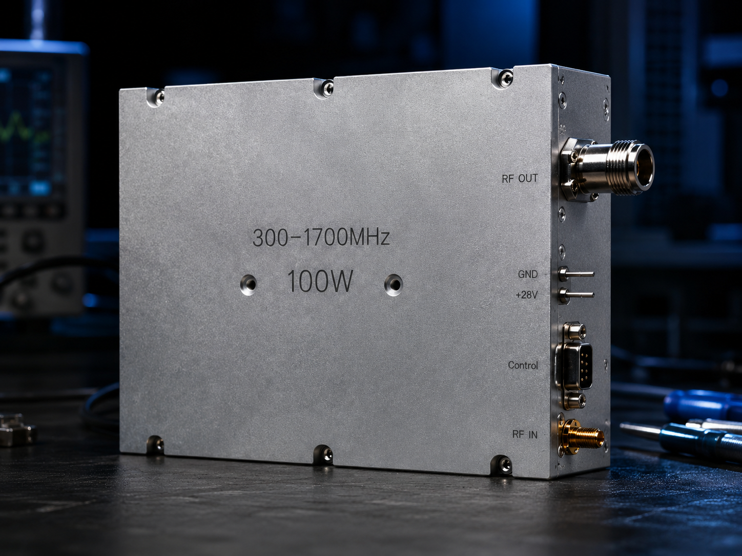
System integrators deploying high-power desert unmanned stations frequently face sudden RF output power drops during midday peak heat. Ambient temperatures swing violently across arid expanses, stressing metal enclosures and internal components relentlessly. We witness field technicians replacing blown modules constantly, blaming generic silicon or gallium nitride defects for these catastrophic failures. But here is the kicker. Laboratory autopsies reveal perfectly functional transistors ruined by basic mechanical assembly errors on site. Unmanned systems demand zero maintenance, demanding rigorous architectural foresight during initial rack integration. Thirty years of manufacturing history at CorelixRF proves that simple mounting negligence destroys sophisticated electronics faster than extreme weather events. You cannot ignore mechanical interfaces when pushing hundred-watt continuous wave signals through compact chassis formats. Trusting theoretical datasheets without executing strict installation protocols guarantees early degradation across remote networks. This technical breakdown examines failure mechanics and provides concrete solutions for surviving brutal thermal environments.
1. Why Do High-Power Desert Unmanned Stations Experience Early RF Degradation?
The Silent Failure at 50 Degrees Celsius
Desert unmanned stations bake continuously under direct solar radiation, elevating internal cabinet temperatures beyond standard operational limits rapidly. We monitor remote diagnostic feeds showing output levels sagging dramatically exactly when daytime heat peaks. Field engineers dispatch teams, carrying expensive spectrum analyzers across dunes, expecting damaged active components or mismatched antenna loads. What’s the real story? Mechanics dictate that uneven fastening sequences create microscopic air gaps beneath amplifier modules. Technicians tightening fasteners in a circle rather than a cross pattern warp aluminum housings slightly. Air acts as an excellent insulator, blocking thermal transfer from hot die junctions directly into main system heat sinks. Temperature gradients steepen drastically near output stages, forcing active devices past their thermal destruction thresholds. GaN technology withstands immense abuse, surviving temperatures approaching two hundred degrees Celsius momentarily. Sustained localized heating degrades electron mobility permanently, causing irreversible gain droop within weeks of initial activation.
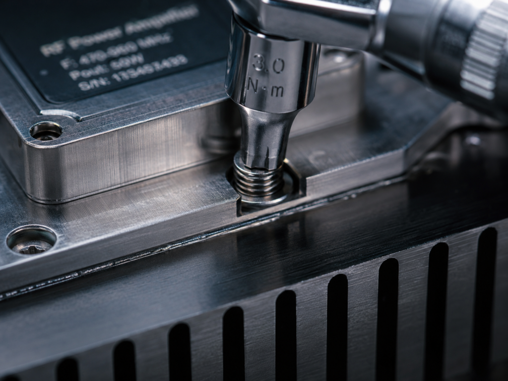
Mechanics of Uneven Heat Dissipation
Baseplate warpage creates uneven pressure distribution across thermal interface materials applied between modules and cooling surfaces. Compressing graphite pads or thermal grease requires uniform torque application across all mounting points simultaneously. This is where it gets interesting. Skipping proper diagonal torque sequences leaves certain corners floating microns above cold plates. Heat flux concentrates entirely on fasteners that were tightened first, overloading those specific thermal pathways instantly. An amplifier drawing up fourteen amps from twenty-eight volt rails dissipates massive energy constantly. Trapped thermal energy reflects back into printed circuit boards, softening solders and shifting impedance characteristics dynamically. Radio frequency matching networks rely heavily on stable physical dimensions, requiring consistent dielectric properties maintained through uniform cooling. When localized spots overheat, adjacent matching capacitors drift out of tolerance, triggering severe mismatch conditions internally.
Baseplate Warpage and GaN Channel Temperatures
Monitoring channel temperatures inside packaged transistors requires understanding thermal resistance networks stretching from die surfaces into ambient air. CorelixRF engineers measure baseplate flatness deviations down into micrometer ranges using precision laser scanning tools. You might be wondering. Why does a single millimeter of torque misalignment matter for high-power desert unmanned stations? Thermal resistance increases exponentially across poorly mated surfaces, adding degrees per watt directly into junction temperature calculations. A hundred watt saturated output module generating sixty watts of waste heat requires zero obstructions along its cooling path. Micro-voids caused by warpage trap this energy, driving channel temps beyond safe continuous operating boundaries quickly. Reliability math shows mean time between failures collapsing drastically for every ten degree rise above base specifications.
Thermal Resistance Impact Based on Mounting Torque
| Parameter | Diagonal Sequence | Circular Sequence | Units |
| Baseplate Flatness Deviation | <0.05 | >0.20 | mm |
| Interface Thermal Resistance | 0.15 | 0.85 | °C/W |
| Die Junction Temp Rise | 25 | 65 | °C |
| Mean Time Between Failures | 150,000 | 12,000 | Hours |
2. How Does Improper Baseplate Mounting Impact Link Budgets?
The Kicker in System Level VSWR
Radio frequency energy traveling through warped modules encounters shifting impedances, bouncing power back toward sensitive driver stages. High-power desert unmanned stations rely upon strict voltage standing wave ratio tolerances for sustained transmission ranges. Here is the deal. When localized heating shifts dielectric constants, internal transmission lines stop matching fifty ohm system requirements perfectly. Output VSWR climbs steadily from a factory-tested 1.5:1 ratio up toward critical 2.0:1 limits under sustained load. Reflected power converts directly into additional waste heat, compounding existing thermal dissipation problems exponentially. Isolators handle some mismatch, dumping reflected energy into termination resistors, but those resistors also rely upon baseplate cooling. Warped chassis connections prevent isolator loads from venting heat, triggering secondary failures cascading backward through entire communication chains.
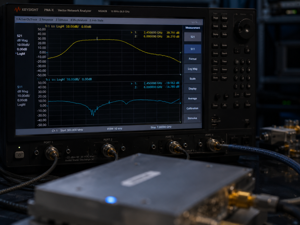
Measuring the Drop via S21 Sweeps
Connecting vector network analyzers during high noon reveals shocking S21 gain degradation curves across compromised hardware. Our CRF-PA-300M1700M-100W specifies forty-nine decibels minimum gain, holding flat within 1.8 decibels across massive bandwidths. Let’s look at the facts. Improperly mounted units exhibit high-frequency gain collapse, dropping three or four decibels randomly as temperatures escalate. Gain flatness curves shown on VNA screens warp severely, failing system integration specifications designed for linear operation. Communication links drop packets rapidly because weakened signals fail minimum receiver threshold demands across distant receiving nodes. Radar systems lose critical resolution capability, failing completely when transmit pulses lack sufficient energy for clear target returns.
Thermal Runaway in Desert Unmanned Stations
Amplifier current consumption creeps upward as transistors heat up, demanding more amperage just maintaining nominal output levels. A module rated for maximum fourteen amps suddenly draws sixteen, stressing remote solar battery banks heavily. Ready for the good part? Protection circuits kick off eventually, shutting down entire arrays suddenly without any prior software warnings. Field maintenance crews arriving days later find modules completely cool, testing perfectly fine under temporary diagnostic loads. Without checking mechanical torque specifications, technicians reinstall compromised gear, guaranteeing identical failures occurring during subsequent heat waves. Engineering truth demands eliminating mechanical variables first before blaming solid state physics for system level communication blackouts.
S-Parameter Degradation During Thermal Runaway
| Measurement | Factory Spec | Warped Mounting | Units |
| S21 Gain at 1 GHz | 50.0 | 46.5 | dB |
| S11 Input Return Loss | -15.0 | -8.0 | dB |
| S22 Output Return Loss | -14.0 | -9.5 | dB |
| Gain Flatness (300-1700MHz) | ≤1.8 | >4.5 | dB |
3. What Architecture Design Mitigates Thermal Stress in Desert Environments?
Rigid Structural Integrity for Baseplates
Designing hardware for high-power desert unmanned stations requires prioritizing mechanical stiffness alongside advanced electrical schematics. Thick baseplates resist bending forces generated by uneven screw tension, distributing localized stress across broader surface areas. What’s the real story? Thin enclosures warp instantly under pressure, destroying delicate internal wire bonds connecting active dies into printed boards. CorelixRF utilizes solid machined aluminum blocks, ensuring maximum rigidity protecting fragile ceramic packages from external mechanical torsion. Four hundred employees working across thirty years refined these machining tolerances, learning exactly how metals behave under extreme stress. Our package sizes measure exactly $200\times158\times25~mm$, providing massive thermal mass capable absorbing transient heat spikes efficiently.
Material Selection for Heat Spreading
Gallium nitride transistors generate intense pinpoint heat sources requiring immediate spreading before hitting main chassis sinks. Traditional copper-tungsten flanges offer good conductivity, transferring thermal loads away from sensitive active channels rapidly. This is where it gets interesting. Selecting proper interface greases matters immensely, bridging microscopic gaps between machined surfaces flawlessly. Phase change materials outperform standard silicon pastes, liquefying exactly at operating temperatures, filling voids created by minor mounting imperfections. We recommend thermal compounds exhibiting resistance lower than 0.1 degrees Celsius per watt for hundred-watt continuous wave applications. Proper material selection prevents localized boiling, stopping rapid degradation cycles common within sealed remote equipment cabinets.
CorelixRF Hardware Integration Protocols
Integrating RF power amplifiers into system racks demands following strict procedural guidelines documented within engineering manuals. Installers must clean all mating surfaces using industrial solvents, removing invisible oxidation layers blocking heat transfer pathways completely. You might be wondering. How do installation instructions differ for the CRF-PA-300M1700M-100W compared against commercial grade audio gear? Our manuals explicitly mandate utilizing calibrated torque drivers, setting exact inch-pound limits matching specific fastener grades perfectly. Workers apply initial torque crossing diagonally, securing center positions first before locking down outer perimeter corners securely. This specific technique pushes trapped air outward, seating modules perfectly flat against cooling blocks without trapping microscopic bubbles.
CorelixRF Baseplate Specification Analysis
| Feature | Specification | Engineering Benefit | Focus Area |
| Material | T6061 Aluminum | High thermal conductivity | Baseplate |
| Thickness | 8 mm minimum | Prevents torque warpage | Structure |
| Surface Finish | < 0.8 Ra | Minimizes interface voids | Mating Surface |
| Fastener Type | M4 Stainless | Sustains high tension | Mounting |
4. How Does the CRF-PA-300M1700M-100W Address Desert Deployment Challenges?
Wideband Performance Under Thermal Load
Deploying radio frequency equipment spanning 300 to 1,700 megahertz requires maintaining stability across massive octave bandwidths. High-power desert unmanned stations utilizing electronic warfare jammers demand instantaneous frequency agility without suffering localized power dropouts. Here is the deal. The CRF-PA-300M1700M-100W maintains fifty decibels typical gain across its entire operating spectrum consistently. Laboratory sweeps show input standing wave ratios staying below 1.8:1 even when ambient temperatures hit eighty-five degrees Celsius. Maintaining wideband matching under severe thermal stress proves our internal compensations networks function perfectly despite external environmental hostility. Continuous wave saturated output remains locked at one hundred watts, providing reliable jamming coverage across designated target areas.
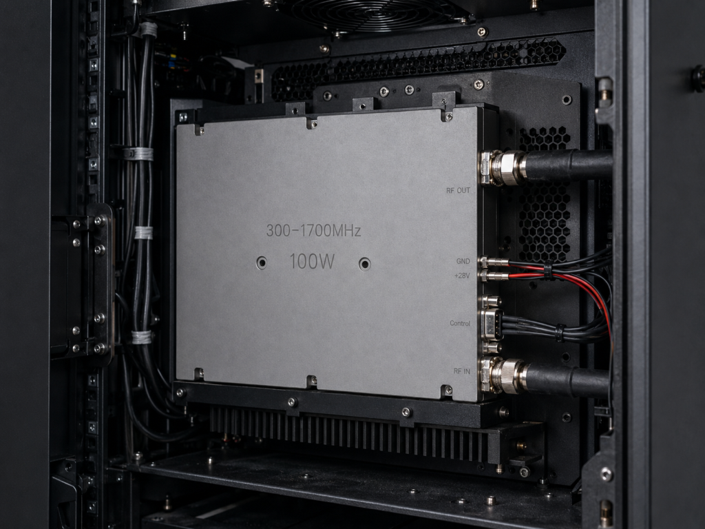
Electrical Characteristics Guarding Against Failure
Operating far from civilization means equipment must survive minor system anomalies without requiring manual resets. We design the CRF-PA-300M1700M-100W utilizing twenty-eight volt direct current rails, keeping current consumption below fourteen amps strictly. Let’s look at the facts. Harmonics stay suppressed below minus ten decibels referenced against carrier frequencies, preventing out-of-band interference generation. Spurious emissions remain exceptionally quiet, measuring better than minus sixty decibels, protecting sensitive co-located receiver arrays completely. These strict electrical characteristics prevent internal feedback loops causing self-destructive oscillation when thermal conditions degrade antenna load impedances suddenly. We guarantee these specifications through rigorous factory burn-in processes, rejecting any unit showing parameter drift during thermal cycling.
Strict Mechanical Mounting Tolerances
Our engineering drawings keep mechanical outlines fully visible, confirming exact connector locations for seamless system integration. SMA-Female input and N-Female output connectors mount securely, handling heavy coaxial cable strain without stressing internal circuit traces. Ready for the good part? The entire module weighs less than 1.4 kilograms, reducing mechanical shear forces applied against vertical mounting brackets. Field technicians utilizing DB9 control interfaces gain immediate access monitoring internal temperatures, allowing remote shutdown before catastrophic failure occurs. CorelixRF engineers provide feasibility reviews within forty-eight hours, assisting system integrators facing complex packaging constraints during initial design phases. We demand strict adherence regarding our published mechanical dimensions, ensuring proper airflow routing across air-cooled heat sink fins.
CRF-PA-300M1700M-100W Core Electrical Specifications
| Parameter | Min | Typ | Max | Units |
| Frequency Range | 300 | – | 1700 | MHz |
| Rated Output Power | 100 | 100 | – | W |
| Gain | 49 | 50 | 51 | dB |
| Current Consumption | – | – | ≤14 | A |
5. What Are the CorelixRF Engineering Truths for Field Technicians?
Mandating the Diagonal Tightening Sequence
Technical documentation frequently ignores basic mechanical realities, assuming field workers understand advanced thermodynamic principles instinctively. CorelixRF enforces strict standard operating procedures regarding fastener installation across every high-power desert unmanned station deployment. What’s the real story? Engineers must label mounting holes numerically, forcing technicians following sequence one through six blindly. Fastening top-left requires immediately fastening bottom-right next, balancing pressure distributions across delicate thermal interface materials flawlessly. We reject warranty claims whenever autopsies reveal warped baseplates caused by lazy circular tightening patterns executing hastily. Engineering truth dictates physical laws govern microwave performance ultimately, punishing anyone ignoring basic mechanical assembly requirements during field installations.
Verifying Flatness Before Powering Up
Applying twenty-eight volts direct current into unverified mechanical assemblies risks destroying expensive gallium nitride transistors instantly. Technicians must insert feeler gauges around module perimeters, checking for gaps exceeding zero point zero five millimeters carefully. This is where it gets interesting. Sliding thin metal strips between amplifiers and cold plates detects hidden warpage caused by improper torque sequences immediately. If gauges penetrate underneath aluminum housings, workers must loosen all fasteners completely, restarting tightening protocols from scratch. Taking five extra minutes verifying physical contact saves weeks waiting for replacement hardware shipping across international borders. System integrators deploying electronic warfare systems cannot afford downtime caused by easily preventable mechanical negligence occurring during final assembly.
Finalizing the Desert Unmanned Station Checklists
Executing flawless deployments requires replacing assumptions with rigorous checklists governing every aspect of remote site commissioning. Connecting vector network analyzers verifying input return loss provides definitive proof regarding internal matching network integrity post-installation. You might be wondering. Does measuring S11 really detect warped baseplates inside sealed aluminum enclosures? Yes, because warped structures stress internal substrates, shifting resonant frequencies visibly across swept S-parameter measurement displays. Checking current draws under zero radio frequency drive confirms bias networks survived mechanical shocks incurred during transport and mounting. Finalizing these checklists guarantees our CRF-PA-300M1700M-100W operates flawlessly across decades, surviving brutal desert environments without human intervention.
Desert Unmanned Station Final Commissioning Checklist
| Inspection Step | Tool Required | Acceptance Criteria | Pass/Fail |
| Thermal Interface Check | Feeler Gauge | < 0.05mm gap | [ ] |
| Fastener Torque Check | Calibrated Wrench | 12 in-lbs ± 1 | [ ] |
| S11 Return Loss Sweep | Vector Network Analyzer | < -10 dB across band | [ ] |
| Quiescent Current Check | DC Power Supply | Matches factory spec | [ ] |
Proper mechanical assembly dictates the survival rate for high-power desert unmanned stations operating under extreme thermal stress. Warped baseplates destroy sophisticated RF amplifiers rapidly, causing irreversible power degradation when field technicians ignore diagonal tightening sequences. Executing precise structural integration guarantees our CRF-PA-300M1700M-100W maintains flawless performance across brutal climates. Contact the CorelixRF engineering team today discussing your specific system architecture requirements and request a comprehensive feasibility review.
FAQ Section
- Q1: What is early RF degradation in desert unmanned stations?Early RF degradation involves irreversible loss of output power caused by sustained localized overheating. When heat cannot escape due to mounting errors, internal channel temperatures destroy transistor electron mobility rapidly.
- Q2: How does diagonal tightening work?Diagonal tightening works by applying pressure across opposing corners sequentially, forcing trapped air outward evenly. This sequence prevents aluminum baseplates from warping, ensuring total physical contact against cooling surfaces.
- Q3: Why do S-parameters change under thermal stress?S-parameters change because excessive heat alters dielectric properties inside printed circuit boards and shifts capacitor values. These physical changes disrupt fifty-ohm matching networks, causing severe gain collapse and increased reflected power.
- Q4: What makes the CRF-PA-300M1700M-100W suitable for extreme heat? This amplifier utilizes a massive machined aluminum baseplate resisting mechanical torsion efficiently. Its conservative twenty-eight volt design minimizes waste heat generation, maintaining stability across massive octave bandwidths.
- Q5: Can warped baseplates be fixed in the field?Warped baseplates caused by improper torqueing can sometimes recover if technicians loosen fasteners and restart tightening sequences immediately. Permanent plastic deformation requires complete module replacement returning original thermal transfer capabilities safely.
Convert thermal risk into measurable RFQ requirements
Thermal reliability should be specified with output power, duty cycle, ambient range, airflow or baseplate path, soak time, allowed gain drift and alarm behavior. These details help CorelixRF match the request to a standard or modified amplifier platform.
Recommended next step: send the operating band, output power target, duty cycle, load condition, control interface, protection or thermal limits and required FAT documents. CorelixRF can review this How to Prevent Baseplate Warpage and Improve RF Amplifier Heat Dissipation? requirement against standard RF amplifier platforms, RF front-end options and controlled customization paths.