
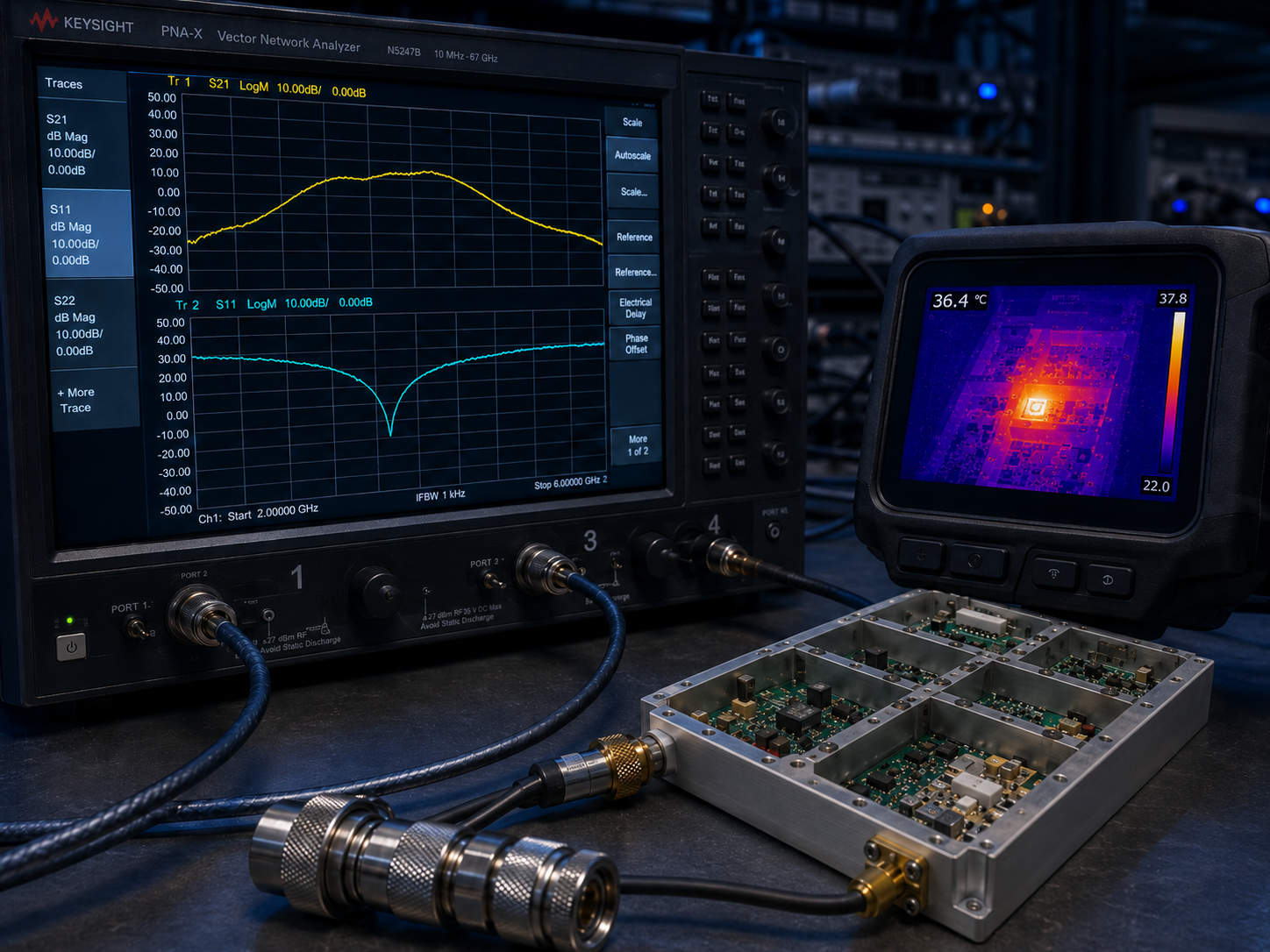
1. How do Unmanned Desert Stations Suffer from RF Signal Anomalies?
Unmanned desert stations face extreme diurnal temperature fluctuations constantly. Engineers often misdiagnose sudden RF power drops across these remote installations. Technicians initially blame failing gallium nitride transistors or power supply voltage sags. Here is the deal, incorrect mechanical mounting practices generate localized hotspots underneath high-power active devices. Neglecting diagonal tightening sequences leaves microscopic air voids between baseplates and heatsinks. These tiny gaps destroy thermal transfer efficiency rapidly. Air acts as an exceptional insulator against conductive cooling mechanisms. We offer comprehensive hardware solutions leveraging precision-machined aluminum housings. Our CorelixRF engineering team guarantees robust hardware survival applying two decades of field troubleshooting experience. Establishing strict installation protocols prevents catastrophic system degradation entirely. Proper torque specifications guarantee optimal physical contact across mating surfaces. Continuous monitoring confirms expected operational longevity during harsh summer conditions. Desert environments demand rigorous mechanical engineering discipline.
Environmental Stress Factors
| Parameter | Field Observation | System Impact |
| Ambient Temperature | Reaches 55°C midday | Increases baseplate baseline temperature |
| Nighttime Drop | Plummets near freezing | Causes rapid metal contraction |
| Solar Loading | Direct sunlight exposure | Adds extraneous thermal mass burden |
| Sand Accumulation | Dust covers external fins | Reduces convective cooling efficiency |
2. Why Does Uneven Baseplate Screw Tightening Cause Premature RF Degradation?
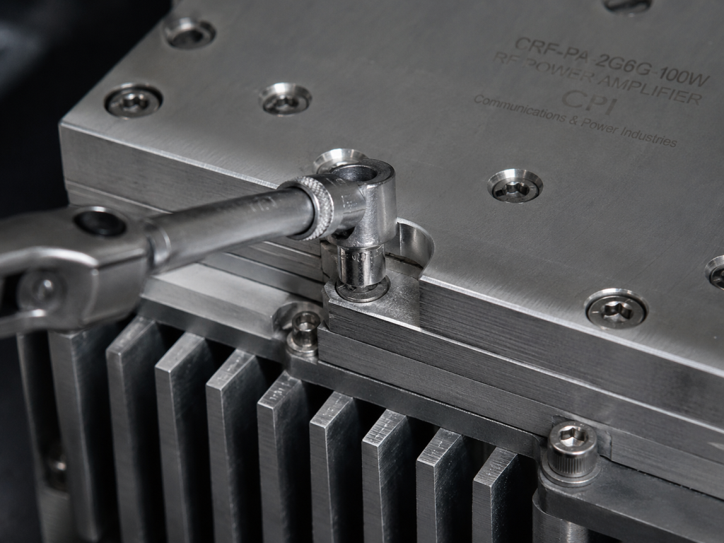
Mechanical stress destroys RF amplifiers functioning inside harsh operating environments. Uneven torque application warps rigid metal structures during initial field installations. Thermal expansion exacerbates micro-fractures within delicate circuit board substrate materials. What is the real story? Tightening one corner fully before addressing opposite sides creates uneven pressure distributions. This flawed methodology bends flat aluminum bases away from mating heatsink surfaces. Heat generated by power transistors cannot escape through trapped air pockets. Localized channel temperatures spike far beyond safe semiconductor operating limits quickly. Premature degradation occurs rapidly under continuous wave operational profiles. Engineers observe dropping output power alongside rising current consumption figures. Tightening baseplate screws diagonally ensures flat uniform contact across thermal interfaces. We mandate using calibrated torque wrenches during every single field deployment. Symmetrical fastening prevents structural warping under severe thermal cycling conditions.
Baseplate Mounting Consequences
| Mounting Error | Physical Result | RF Performance Impact |
| Linear Tightening | Baseplate warping | Immediate localized overheating |
| Insufficient Torque | Thick thermal paste layer | Gradual power compression |
| Over-Torquing | Stripped mounting threads | Complete mechanical failure |
| Uneven Sequence | Microscopic air voids | Accelerated transistor degradation |
3. How Can Engineers Identify Thermal Stress Using RF Test Equipment?
Field diagnostics require specific instrumentation deployment measuring real-time signal integrity. Technicians utilize directional couplers monitoring forward and reflected power simultaneously. Spectrum analyzers reveal rising noise floors indicating severe thermal runaway situations. This is where it gets interesting Unmanned stations exhibiting high temperature alarms often show distorted high-frequency signal envelopes. Oscilloscope measurements display clipped waveforms during maximum power transmission bursts. Input drive levels remain constant while output magnitude drops significantly. Current probes clamped around DC supply lines register abnormal spikes. These electrical symptoms confirm failing thermal dissipation paths underneath active components. Engineers must measure physical casing temperatures using calibrated infrared thermal imaging cameras. Hotspots appearing near final stage transistor locations prove mounting defects exist. Identifying uneven baseplate screw tightening early saves expensive communication infrastructure replacement costs.
Diagnostic Equipment Utilization
| Instrument Type | Monitored Parameter | Thermal Stress Indicator |
| Directional Coupler | Forward/Reflected Power | Dropping output magnitude |
| Spectrum Analyzer | Signal Spurious Emissions | Rising noise floor levels |
| Oscilloscope | RF Waveform Envelope | High-temperature amplitude clipping |
| Infrared Camera | Baseplate Surface Temperature | Concentrated localized hot zones |
4. What Mechanical Rigidity Solutions Does CorelixRF Offer?
We design ruggedized power amplifiers surviving extreme environmental deployment scenarios. The CRF-PA-2G6G-100W model delivers robust performance across wideband frequency spectrums. Our manufacturing process ensures perfectly flat baseplate machining tolerances consistently. Ready for the good part? This specific broadband RF power amplifier guarantees 100 W output power continuously. Operating safely across a 2,000-6,000 MHz frequency range demands superior mechanical foundations. We specify utilizing proper thermal grease layers eliminating trapped air completely. Four strategically placed mounting holes require diagonal tightening sequences strictly. Engineers must apply equal rotational force utilizing specialized industrial fastening tools. This precision guarantees maximum thermal conductivity extracting heat away rapidly. Our rigid aluminum chassis prevents mechanical flexing during heavy vibration events. Proper installation procedures protect delicate internal matching networks completely.
Product Mechanical Specifications
| CorelixRF Parameter | Datasheet Value | Field Application Benefit |
| Model Number | CRF-PA-2G6G-100W | Wideband radar compatibility |
| Package Size | 200 x 158 x 25 mm | Compact unmanned station integration |
| Weight | ≤1.4 kg | Minimizes structural mast loading |
| Cooling Method | Air Cooling | Eliminates complex liquid systems |
5. How Are Electrical Characteristics Maintained Under Thermal Stress?
Maintaining linear amplification requires strict adherence concerning maximum case temperature limits. Poorly mounted units exhibit severe gain compression across upper frequency bands. Proper heat sinking allows transistors operating near maximum rated voltage safely. But wait, there is more The CRF-PA-2G6G-100W requires 41-51 VDC supply voltage generating massive thermal energy. Current consumption reaches ≤24 A during saturated continuous wave operation. Diagonal baseplate screw tightening dissipates this immense energy load efficiently. Perfect thermal contact maintains typical gain around 50 dB steadily. Flatness remains ≤1.8 dB ensuring distortion-free signal transmission over wideband spectrums. Harmonics stay suppressed below -10 dBc meeting strict regulatory compliance standards. Effective mechanical mounting guarantees stable electrical parameters over years spanning continuous service.
CorelixRF Electrical Parameters
| Specification | Datasheet Limits | Thermal Dependency |
| Frequency Range | 2,000-6,000 MHz | Bandwidth narrows during overheating |
| Gain | 49 Min, 51 Max dB | Drops rapidly near thermal limits |
| Supply Voltage | 41 Min, 51 Typ VDC | Demands efficient heat extraction |
| Current Consumption | ≤24 A | Spikes exponentially under stress |
6. What Environmental Tolerances Ensure Long-Term Survival?
Remote desert installations experience brutal climate variations challenging electronic hardware durability. Systems must withstand freezing nights followed by scorching afternoon temperatures. Condensation forms internally causing severe corrosion without proper conformal coating applications. You might be wondering… Our amplifiers support an operating temperature range spanning -40°C reaching +85°C. Storage temperature limits mirror these extreme boundaries guaranteeing safe transportation logistics. We implement rigorous ISO 9001 quality framework manufacturing standards continuously. GJB 9001C compliance ensures military-grade reliability concerning structural integrity. Mean time between failures data remains available upon request supporting project reviews. However, all these certifications become useless ignoring basic installation mechanics. Failing to execute tightening baseplate screws diagonally voids thermal survival capabilities. Properly mounted units outlast generic commercial alternatives operating inside harsh environments easily.
Environmental Tolerance Data
| Metric | Specification Limit | Field Significance |
| Operating Temperature | -40°C to +85°C | Survives desert diurnal shifts |
| Storage Temperature | -40°C to +85°C | Prevents transport degradation |
| Quality Standard | ISO 9001 | Ensures manufacturing consistency |
| Defense Standard | GJB 9001C | Validates military robustness |
7. How Are Broad-Band Power Amplifiers Adapted for Complex Integration?
System integrators face unique challenges deploying high-power RF modules externally. Antenna structures demand precise impedance matching preventing destructive reflected energy. Connection interfaces must withstand heavy mechanical torque without snapping internal conductors. Let me explain… We provide SMA-Female connectors handling delicate RF input signals safely. Rugged N-Female connectors deliver massive RF output power reliably. DB9 control interfaces manage external monitoring telemetry data efficiently. CorelixRF engineering teams review custom feasibility requests within 48 hours. Custom frequency bands and unique control interfaces remain available matching project demands. Integrating these modules requires absolute precision regarding physical baseplate mounting. Symmetrical clamping force prevents torque transfer damaging delicate coaxial connector joints. Solid mechanical grounding ensures stable reference potentials eliminating erratic operational behaviors entirely.
Interface Integration Connectors
| Interface Function | Connector Type | Mechanical Benefit |
| RF Input | SMA-Female | Secure low-power signal coupling |
| RF Output | N-Female | High-power ruggedized transmission |
| Control Interface | DB9 | Standardized telemetry connections |
| Customization | Upon Request | Adapts unique system requirements |
8. Why Is Verifying Amplifier Performance Through Network Analysis Necessary?
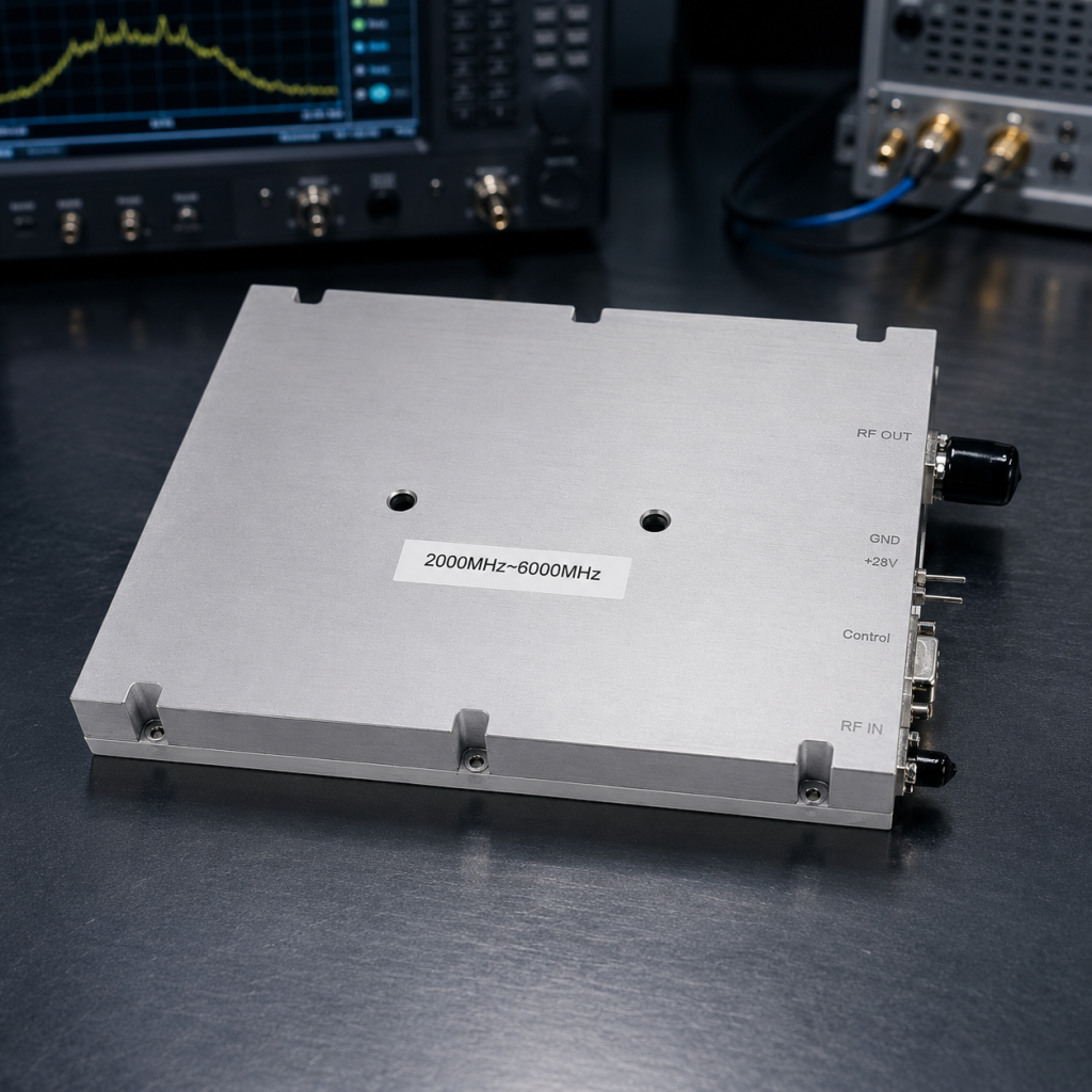
Vector network analyzers provide absolute truth concerning RF circuit health. Swept frequency measurements expose impedance mismatches hidden deep inside amplifier structures. Analyzing forward transmission coefficients reveals exact gain profiles across operating bands. Consider this… Our datasheet includes representative swept measurement curves displaying gain versus frequency. Tr1 corresponds clearly indicating S21 gain dynamics hovering near 50dB. Tr2 highlights input match S11 voltage standing wave ratio stability. Input VSWR remains strictly ≤1.8:1 preventing generator mismatch issues. Output VSWR stays ≤2.0:1 protecting internal transistors against moderate load reflections. Severe thermal stress degrades these precise network analyzer curves dramatically. High temperatures cause substrate dielectric constants shifting unpredictably. Proper diagonal screw torquing preserves baseline S-parameter measurements matching factory calibration certificates.
Network Analysis Parameters
| S-Parameter | Datasheet Performance | Degradation Symptom |
| S21 (Gain) | ~50 dB trace | High-frequency curve collapse |
| S11 (Input Match) | VSWR ≤1.8:1 | Trace spikes indicating reflection |
| Output VSWR | ≤2.0:1 | Severe power reflection damage |
| Measurement Range | 2 to 6 GHz | Bandwidth narrowing effects |
9. How Do Mechanical Drawings Guide Proper Heatsink Mating?
Detailed mechanical outlines prevent catastrophic field installation errors completely. Engineers must design custom heatsinks matching amplifier footprint dimensions perfectly. Ignoring exact hole placements leads toward stripped threads destroying expensive chassis components. Why does this matter? We provide complete outline drawings establishing clear integration reference points. Mechanical drawings remain fully visible ensuring easier dimensional review processes. Connector location confirmation prevents cable routing stress during final cabinet assembly. The 200 mm length requires six distinct mounting points securing heavy structures. Applying torque diagonally across these specific points guarantees flat baseplate seating. Thermal compound spreads evenly filling microscopic surface imperfections entirely. Technicians consulting precise mechanical diagrams avoid costly structural warping mistakes. Proper visualization ensures successful deployment inside cramped unmanned desert equipment shelters.
Dimensional Verification Metrics
| Physical Dimension | Value | Integration Requirement |
| Total Length | 200 mm | Requires multi-point torque |
| Total Width | 158 mm | Defines thermal contact area |
| Total Height | 25 mm | Limits vertical cabinet space |
| Documentation | Kept fully visible | Guides technician installation |
10. What Installation Protocols Prevent Unmanned Site Failures?
Standardized installation procedures eliminate human error during complex RF system deployments. Training field technicians regarding mechanical best practices yields massive reliability improvements. Simple torque sequencing errors destroy thousands concerning dollars worth utilizing advanced GaN hardware. The bottom line Symmetrical baseplate screw tightening prevents localized thermal runaway events fundamentally. Engineering truth demands respecting physical thermodynamic laws governing semiconductor reliability. Heat must escape through zero-resistance mechanical pathways ensuring long-term survival. CorelixRF builds uncompromising RF power amplifiers surviving brutal operational realities. We urge system integrators demanding meticulous mechanical fastening protocols across all deployments. Review our comprehensive datasheets understanding exact physical mating requirements fully. Contact our engineering team discussing custom thermal management solutions solving unique challenges. Robust communication networks depend entirely upon flawless physical infrastructure foundations.
Field Installation Checklist
| Protocol Step | Technician Action | Critical Outcome |
| Surface Prep | Clean baseplate using alcohol | Removes debris causing air gaps |
| Compound App | Apply thin thermal grease | Fills microscopic metal imperfections |
| Initial Seating | Hand-tighten all screws lightly | Aligns chassis without warping |
| Final Torque | Use wrench turning diagonally | Secures flat uniform thermal contact |
FAQ Section
Q1: How do Unmanned Desert Stations Suffer from RF Signal Anomalies?
Unmanned stations suffer because extreme diurnal temperature shifts exacerbate poor mechanical mounting practices. When technicians fail executing diagonal tightening sequences, microscopic air voids form between baseplates and heatsinks. These gaps destroy thermal conductivity, causing localized transistor hotspots and severe RF power degradation rapidly.
Q2: Why Does Uneven Baseplate Screw Tightening Cause Premature RF Degradation?
Uneven torque warps rigid metal baseplates away from mating heatsink surfaces. This traps air pockets acting as thermal insulators directly underneath high-power RF transistors. The inability transferring heat away causes channel temperatures spiking beyond safe limits, resulting in rapid power compression.
Q3: How Can Engineers Identify Thermal Stress Using RF Test Equipment?
Engineers deploy spectrum analyzers revealing rising noise floors and oscilloscopes showing clipped RF waveforms. Directional couplers indicate dropping forward output magnitude despite constant input drive levels. Additionally, monitoring abnormal spikes across current consumption figures confirms failing thermal dissipation paths exist.
Q4: What Mechanical Rigidity Solutions Does CorelixRF Offer?
CorelixRF designs ruggedized aluminum chassis modules like the CRF-PA-2G6G-100W featuring precision-machined flat baseplates. This specific 100 W amplifier requires symmetrical fastening across strategic mounting holes. Utilizing proper torque tools ensures maximum thermal conductivity extracting heat away rapidly.
Q5: How Are Electrical Characteristics Maintained Under Thermal Stress?
Maintaining parameters like ≤1.8 dB gain flatness and ≤24 A current consumption requires efficient cooling. Diagonal baseplate screw tightening dissipates massive thermal energy loads reliably. Perfect thermal contact allows transistors operating safely across wideband spectrums without suffering destructive gain compression.
Translate desert-site anomalies into operating requirements
For hot or dusty sites, define ambient range, enclosure, airflow, duty cycle, output power, grounding, connector exposure and acceptable gain drift. This helps decide whether a rugged platform, thermal change or RF-chain review is needed.
Recommended next step: send the operating band, output power target, duty cycle, load condition, control interface, grounding or thermal limits and required FAT documents. CorelixRF can review this desert site RF signal anomalies requirement against standard RF amplifier platforms, RF front-end options and controlled customization paths.