
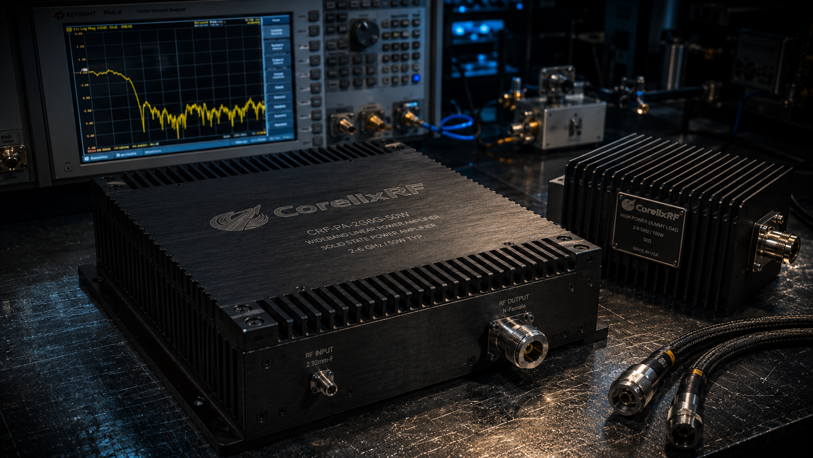
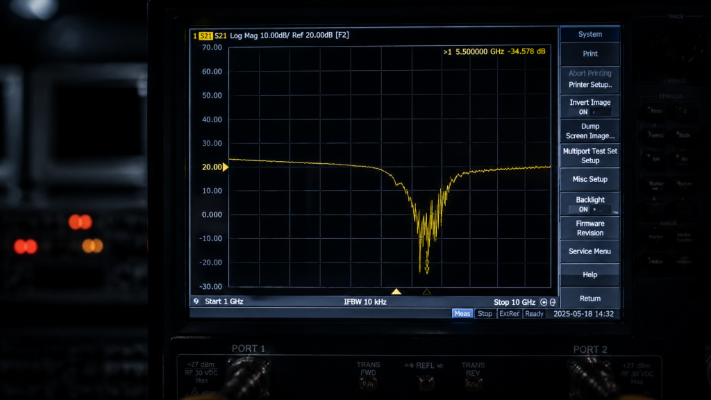
Engineers often face unexpected vector network analyzer trace degradation when extracting gain flatness test data during high-power evaluations. You push 50W CW power through your bench setup expecting flat responses but notice bizarre 3dB dips near 5.5 GHz. Here is the deal: cascaded uncalibrated attenuators frequently introduce hidden mismatch uncertainties skewing fundamental gain flatness test data entirely. Implementing rigorous calibration planes combined alongside deploying reliable hardware like our CRF-PA-2G6G-50W wideband RF power amplifier resolves false anomalies permanently. CorelixRF leverages decades of hardcore manufacturing expertise engineering truth into every component eliminating phantom laboratory errors.
1. What Causes Gain Flatness Test Data Distortion in Microwave Laboratories?
● Defining typical lab measurement discrepancies
● Identifying faulty hardware chains
● Examining baseline thermal drift
Defining typical lab measurement discrepancies
Microwave laboratories present unique challenges where precision directly dictates project viability. Technicians regularly stack multiple generic 20dB attenuators attempting thermal protection for sensitive VNA input ports during high-drive scenarios. This improvised cascade creates severe impedance mismatches across broad spectrums like 2,000-6,000 MHz. You might be wondering: why does this specific arrangement corrupt base metrics? Reflections bounce repeatedly between uncalibrated connector interfaces altering perceived magnitude responses drastically. Consequently researchers record distorted gain flatness test data instead of authentic amplifier behavior. Such phantom ripples force unnecessary redesign iterations wasting critical project schedules. We see frontline operators chasing phantom targets adjusting bias currents when fundamental issues originate entirely from poor passive component coupling. Validating absolute signal integrity demands eliminating cascading practices immediately while securing precision-characterized high-power loads.
Attenuation Cascade Impact on VSWR | Single Characterized Load | Dual Uncalibrated Cascade | Triple Uncalibrated Cascade
Mismatch Uncertainty | Minimal | Moderate | Severe
Insertion Phase Error | Stable | Variable | Highly Unpredictable
Gain Flatness Test Data | Authentic | Skewed | Invalidated
2. How Do Cascaded Uncalibrated Attenuators Compromise VNA Measurements?
● Analyzing connector interface reflections
● Tracking cumulative insertion loss
● Revealing phase distortion vectors
Analyzing connector interface reflections
Every RF adapter inserted into a measurement chain degrades complete system directivity measurably. Laboratory personnel frequently overlook how stacking commercial-grade pads shifts calibration reference planes away from intended device ports. What is the real story? An initial VNA calibration might look pristine using standard kits until you introduce mismatched loads operating at 58 VDC high-drive conditions. Unaccounted leakage currents combined alongside reactive loading heavily skew recorded gain flatness test data upwards of several decibels near higher band edges. System integrators relying upon these compromised sweeps miscalculate critical link budgets for radar or electronic warfare platforms. Our field troubleshooting consistently reveals substituting stacked arrays with single high-precision dummy loads restores baseline fidelity instantly. Securing accurate gain flatness test data requires obsessive attention regarding every single connector mating torque value across testing benches.
3. Why Do High-Frequency Traces Collapse During Power Amplifier Validation?
● Investigating dielectric losses
● Diagnosing instrument noise floor limits
● Solving calibration degradation
Investigating dielectric losses
Trace collapse frequently plagues validation phases when operating near 6,000 MHz boundaries. Junior engineers often misinterpret sudden S21 magnitude drops as internal transistor saturation rather than external component failure. This is where it gets interesting: cheap attenuators utilize inferior dielectric materials exhibiting nonlinear absorption rates under continuous 50W thermal stress. Heat accumulation shifts resistance values dynamically while a sweep occurs causing artificial high-frequency roll-off. Consequently technicians capture compromised gain flatness test data falsely penalizing otherwise healthy amplifier modules. True engineering truth requires verifying thermal stability across your entire test apparatus before blaming active devices. We mandate rigorous pre-testing utilizing known-good reference standards guaranteeing absolute confidence before pushing RF power through any new setup. Protecting gain flatness test data integrity demands removing volatile variables from your signal path entirely.
Frequency Response Anomalies | True Device Roll-off | Attenuator Thermal Drift | Connector Mismatch
S21 Trace Behavior | Consistent | Drifting during sweep | Rippled across band
Temperature Dependency | Moderate | Extreme | Low
Impact on Gain Flatness Test Data | Real | Fabricated | Distorted
4. What Instrumentation Setup Prevents Gain Flatness Test Data Errors?
● Standardizing connection protocols
● Establishing firm reference planes
● Minimizing adapter usage
Standardizing connection protocols
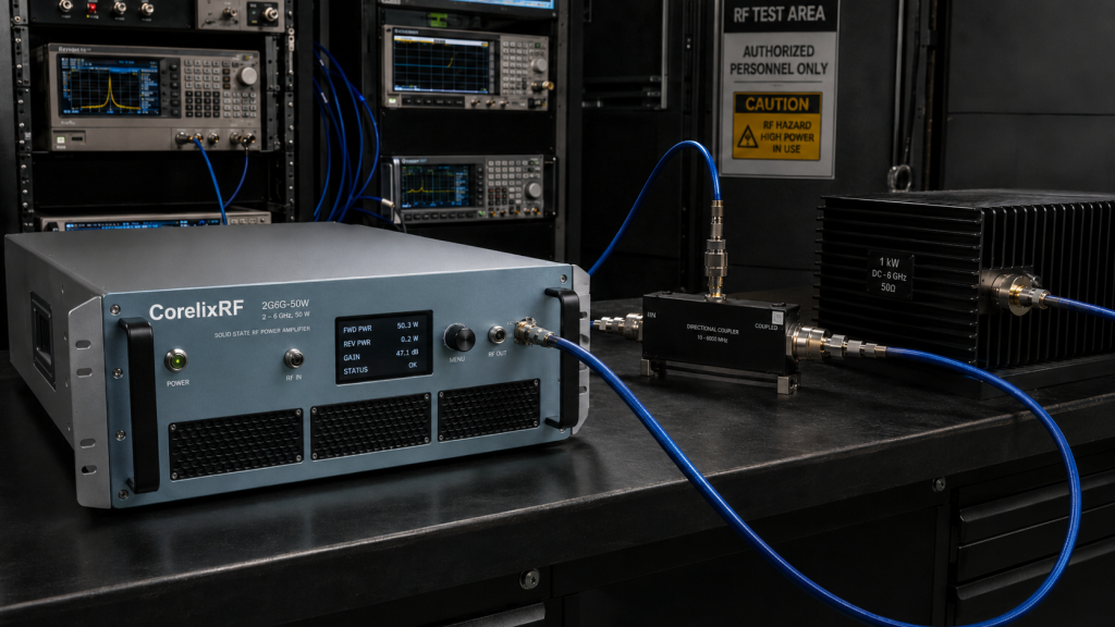
Constructing an infallible test bench requires ruthless elimination of unnecessary adapters bridging dissimilar coaxial interfaces. We strongly advocate utilizing high-grade phase-stable cables connecting directly between amplifier output ports and precision power meters. Ready for the good part? Proper setups utilize directional couplers providing heavily attenuated forward sample ports while terminating main power safely into massive heatsink-equipped loads. This architectural approach isolates delicate spectrum analyzers from destructive transient spikes maintaining pristine gain flatness test data continuously. Field troubleshooting becomes remarkably straightforward when your physical layer guarantees absolute measurement transparency without hidden reactive elements. Eliminating uncalibrated cascaded attenuators removes baseline uncertainties permitting operators focusing strictly upon actual hardware performance metrics. Acquiring authentic gain flatness test data establishes a solid foundation dictating downstream system integration success seamlessly.
5. How Does the CRF-PA-2G6G-50W Guarantee Authentic Output Power Metrics?
● Reviewing baseline power capabilities
● Analyzing gain consistency
● Detailing connector durability
Reviewing baseline power capabilities
CorelixRF designs physical hardware respecting fundamental electromagnetic principles rather than relying upon aggressive digital compensation tricks. Our CRF-PA-2G6G-50W wideband RF power amplifier delivers 50 W output power reliably spanning 2,000-6,000 MHz. But here is the kicker: we achieve a typical gain of 47 dB while maintaining exceptional gain flatness at $\le1.8$ dB. This hardware consistency prevents researchers second-guessing their test results during complex system integration phases. We utilize robust SMA-Female RF input connectors paired alongside heavy-duty N-Female RF output connectors handling massive energy transfers effortlessly. Such mechanical rigidity minimizes insertion phase variances stabilizing raw gain flatness test data effectively regardless of environmental vibrations. Deploying reliable manufacturing tolerances means military-grade contractors receive predictable hardware matching published datasheet specifications perfectly every single time.
CRF-PA-2G6G-50W Core Parameters | Parameter | Typical Value | Maximum Value
Frequency Range | 2,000-6,000 MHz | N/A | N/A Output Power | 50 W | N/A | N/A Gain | 47 dB | 48 dB | N/A Gain Flatness | N/A | 1.8 dB | N/A
6. Why Are Wideband RF Power Amplifiers Vulnerable to Poor Input VSWR?
● Evaluating signal reflection mechanics
● Measuring standing wave impact
● Protecting internal driver stages
Evaluating signal reflection mechanics
Broadband modules operating across multi-octave ranges remain exceptionally sensitive towards impedance mismatches presented by poorly characterized laboratory equipment. Reflected energy bouncing backwards from an uncalibrated attenuator chain interacts destructively against forward traveling waves generating massive voltage standing waves. Look at it this way: these internal reflections corrupt baseline gain flatness test data creating artificial peaks alongside deep nulls appearing randomly across frequency domains. The CRF-PA-2G6G-50W mitigates external volatility utilizing robust matching networks achieving an input VSWR measuring strictly 1.8:1. We guarantee stable energy transfer keeping spurious emissions below -60 dBc maintaining clean spectrum analyzer traces during rigorous evaluation phases. Controlling voltage standing wave ratios rigidly preserves fundamental gain flatness test data integrity preventing false system failures.
7. What Role Does Thermal Management Play in Stabilizing Gain Flatness Test Data?
● Evaluating continuous wave stress
● Analyzing thermal dissipation paths
● Maintaining steady bias currents
Evaluating continuous wave stress
Pushing continuous wave CW/Saturated output power generates extreme heat loads requiring aggressive physical dissipation strategies. Inadequate cooling allows internal substrate temperatures rising rapidly shifting transistor operating points unpredictably during long automated sweeps. Truth be told: thermal drift manifests directly as low-frequency gain expansion followed immediately by high-frequency trace collapse skewing gain flatness test data terribly. We optimized mechanical outline dimensions measuring exactly 200\times158\times25~mm providing massive surface areas facilitating rapid air cooling transfers. Keeping weight restricted strictly below 1.4 kg allows straightforward laboratory mounting without overstressing delicate test fixtures. Maintaining strict thermal equilibrium prevents parameters wandering guaranteeing your gain flatness test data reflects true electrical capability rather than mechanical overheating.
Mechanical & Environmental Data | Characteristic | Value | Notes
Dimensions | 200\times158\times25~mm | CorelixRF design | Precision machined housing Weight | 1.4 kg | Highly portable | Ideal for test benches Cooling Method | Air Cooling | Forced airflow recommended | Prevents thermal drift Operating Temperature | -40 to +85 °C | Wide thermal tolerance | Secures data stability
8. How Do System Integrators Correct Field Troubleshooting Calibration Discrepancies?
● Executing thorough de-embedding
● Verifying reference standards
● Validating dynamic range limits
Executing thorough de-embedding
Isolating device performance requires mathematically removing test fixture influences utilizing advanced vector network analyzer de-embedding algorithms systematically. Senior technicians capture S-parameters representing adapters prior inserting active modules establishing completely transparent measurement planes accurately reflecting hardware capabilities. Here is the secret: failing proper de-embedding protocols guarantees cascaded attenuator errors embed themselves permanently within your final gain flatness test data reports. We recommend verifying equipment dynamic ranges confirming signal levels remain comfortably above ambient noise floors preventing trace jitter. Validating test loops utilizing short-open-load-through standard kits confirms absolute system integrity prior applying 40 VDC primary power supplies. Thorough field troubleshooting demands uncompromising methodology separating physical amplifier flaws from localized laboratory environment artifacts confidently.
9. What Mechanical Outline Features Support Reliable RF Testing Benches?
● Mounting hole configurations
● Connector spacing geometry
● Grounding terminal robustness
Mounting hole configurations
Physical instability ruins high-frequency measurements faster than almost any electrical fault imaginable during intensive laboratory validation procedures. Loose coaxial connections introduce phase noise completely obliterating otherwise perfect gain flatness test data across upper microwave bands. Now consider this: our mechanical outline drawing clearly details strategic mounting hole placements guaranteeing rock-solid chassis integration preventing microscopic vibrations. We position DB9 control interfaces logically distant from massive RF power connectors minimizing accidental cable strain during rapid test reconfigurations. Dedicated ground terminals spanning 7.2 mm guarantee massive fault current return paths protecting delicate internal bias circuitries effectively. Securing physical testing infrastructure comprehensively eliminates transient mechanical variables preserving fundamental gain flatness test data consistency perfectly.
Interface Connector Specifications | Port Type | Connector Style | Core Function
RF Input | SMA-KFD46 | Precision signal injection | Handles driver power RF Output | N-Female | High-power transfer | Delivers 50W output Control Interface | DB9 | System monitoring | Remote telemetry access
10. How Should Engineers Execute Final Microwave Lab Validation Procedures?
● Sequencing power-up steps
● Monitoring current consumption
● Documenting final performance records
Sequencing power-up steps
Executing flawless validation demands strict adherence regarding hardware sequencing preventing catastrophic transient voltage spikes destroying sensitive electronics. Operators must verify baseplate thermal contact while applying proper 58 VDC potentials monitoring current consumption rigidly below 12 A. The bottom line is: pushing 6 dBm input drive requires absolute certainty terminating loads safely dissipate subsequent energy bursts without reflecting power. We observe harmonics remaining strictly below -10 dBc confirming linear operation generating pristine gain flatness test data consistently. Thorough field troubleshooting methodology relies heavily upon documenting baseline states allowing future comparisons identifying subtle hardware degradations over extended operating lifespans. Acquiring authentic gain flatness test data confirms operational readiness empowering defense contractors deploying complex radar architectures confidently.
Securing authentic gain flatness test data demands eliminating cascaded uncalibrated attenuators causing hidden impedance mismatches during laboratory validation phases. CorelixRF CRF-PA-2G6G-50W wideband RF power amplifiers provide exceptional baseline stability preventing measurement distortions across critical bandwidths. Contact our technical engineering team today evaluating precision hardware solutions crafted strictly for rigorous B2B system integration challenges.
Q1: What causes gain flatness test data distortion in microwave laboratories?
Cascaded uncalibrated attenuators create severe impedance mismatches reflecting RF energy unpredictably, heavily distorting measured amplifier magnitude responses.
Q2: How does the CRF-PA-2G6G-50W maintain stable output metrics? By utilizing robust matching networks, managing input VSWR below 1.8:1, and leveraging massive mechanical heat sinks dissipating thermal drift.
Q3: Why do high-frequency traces collapse during VNA validation sweeps? Cheap attenuator dielectric materials shift resistance values dynamically under 50W continuous wave thermal stress causing artificial high-frequency roll-off.
Q4: What instrumentation setup prevents hidden calibration errors?
Using single precision-characterized high-power loads alongside directional couplers instead of stacking multiple low-grade commercial pads on VNA ports.
Q5: How should system integrators correct field troubleshooting discrepancies?
Operators must execute thorough vector network analyzer de-embedding protocols validating reference standards before applying primary DC power supplies.
Turn lab data problems into a repeatable test setup
Distorted gain flatness data can come from cables, calibration, load condition, power level, thermal drift or instrument setup. Share the target curve list and setup constraints so engineering can review the full measurement chain.
Recommended next step: send the operating band, target output power, duty cycle, thermal or load condition, control interface, protection behavior and required FAT documents. CorelixRF can review this microwave lab gain flatness test data requirement against standard amplifier platforms, RF front-end options and custom engineering constraints.