
Engineering Decision and RFQ Checklist
This page is now treated as a primary RF engineering guide for gain flatness, calibration chain, sweep setup and acceptance limits. Use the checklist below to turn the article into a buyer-ready RFQ and factory review package.
| Decision Area | What to Confirm | Evidence to Request |
|---|---|---|
| Operating condition | Band, output power, duty cycle, waveform or sweep condition. | Rated operating table and test setup notes. |
| Interface | RF connector, load or antenna condition, control interface and power supply. | Interface drawing, control table and connector limits. |
| Reliability | Thermal path, protection behavior, enclosure airflow and environmental margin. | Thermal data, protection event notes and inspection records. |
| Acceptance | Gain, flatness, power, mismatch behavior, stability or repeatability limits. | FAT checklist, calibration state and final test curves. |
- RFQ checklist – convert requirements into buyer-ready fields.
- RF configurator – summarize band, power, interface and duty-cycle requirements.
- Delivery documentation – align test curves and FAT-style evidence.
- Case studies – compare how engineering issues become procurement decisions.
- Contact CorelixRF – send the requirement package for review.
Primary Topic Hub and RFQ Path
This primary guide now consolidates related RF engineering references. Use it for the current technical explanation, RFQ preparation, factory review and delivery documentation path.
- How to Prevent Gain Flatness Distortion at 40GHz? – consolidated reference
The purpose is to reduce duplicate SEO pages while keeping buyers on one stronger engineering guide with clearer RFQ and documentation paths.
- RFQ checklist – prepare band, power, duty cycle, interface, cooling and acceptance inputs.
- RF configurator – turn project requirements into a first engineering brief.
- Delivery documentation – align test curves, inspection records and FAT-style evidence.
- Case studies – review how CorelixRF frames RF problems for buyer decisions.
- Contact engineering sales – submit the documented scope for review.
Uncalibrated series components destroy microwave measurement accuracy frequently. Proper architectural design alongside robust amplifiers fixes these persistent errors. CorelixRF delivers absolute engineering truth through thirty years of dedicated hardware manufacturing. We resolve specific high-frequency testing failures inside complex laboratory environments daily.
1. How do uncalibrated series attenuators distort high-frequency VNA measurements?
Microwave laboratory architectures demand absolute precision during every test phase. Vector network analyzers reveal brutal system realities immediately upon connection. Engineers often cascade cheap attenuators trying saving project budget costs. They expect flat frequency responses across broad operating bands routinely. But here is the kicker. Those uncharacterized pads introduce massive mismatch uncertainty into your setup. Reflections bounce between unmatched ports continuously creating massive interference patterns. This standing wave interaction ruins your mathematical baseline calibration completely. High-frequency sweeps show sudden curve collapses above 18 GHz constantly. You think your prototype failed suddenly under heavy thermal load. Reality points directly toward poor test bench architecture instead. A 3dB pad with poor VSWR destroys measurement integrity completely. System integrators waste weeks troubleshooting phantom hardware issues needlessly. We trace these anomalies straight back toward uncalibrated passive components. Phase shift errors compound at every single coaxial connector interface. Validating every cascaded element becomes an absolute engineering necessity. Uncalibrated hardware creates a false narrative regarding true device capability. Radar developers cannot tolerate arbitrary gain ripples during system integration. Every component in a series chain multiplies overall standing waves. VNA screens display deep nulls instead of expected flat lines. This physical phenomenon occurs due strictly toward severe impedance mismatches. Factory testing protocols demand mathematically verified reference planes always. Precision requires rigorous documentation covering all cascading test bench cables. Engineers must verify attenuation values across full operational frequency bands. Blindly trusting nominal specifications leads directly toward catastrophic project failures.
Mismatch Error Parameters
| Parameter | Poor Setup | Ideal Architecture |
| High-Band Collapse | Frequent | Eliminated |
| Phase Error | High | Calibrated |
| Measurement Confidence | Low | Absolute |
2. Why does gain flatness degradation occur in 2-26.5 GHz broadband setups?
Broadband measurements from 2,000 through 26,500 MHz expose fundamental flaws. Test setups rarely maintain constant impedance over such wide spans. What is the real story? Parasitic capacitance within series components dominates high-frequency behavior completely. This dynamic directly degrades expected gain flatness ruining test metrics. VSWR interactions multiply across every cascaded coaxial junction continuously. Swept frequency errors manifest as repeating ripple patterns across screens. These ripples mask your device’s actual RF performance characteristics entirely. Harmonic accumulation presents another serious architectural challenge for laboratory teams. Unfiltered harmonics reflect back into driving stages causing severe instability. This creates unpredictable intermodulation distortion products muddying baseband signals. Microwave engineers must account for all these physical parasitic effects. Otherwise, recorded data represents bench artifacts rather than real device capabilities. Proper architectural planning eliminates these cascading failure modes permanently. A poorly designed test rig acts like a complex filter. It attenuates specific frequencies while arbitrarily amplifying others unpredictably. Broadband performance evaluation requires completely neutral measurement pathways always. Any reactive element inserted into a signal path alters phase. We observe these issues frequently inside demanding defense contractor laboratories. They struggle correlating field results with pristine software simulation models. The discrepancy originates almost entirely from undocumented bench parasitics. Hardware developers spend hours chasing problems existing only inside cables. You must build setups presenting zero reactive impedance shifts.
3. What are exact link budget considerations for laboratory architectures?
Developing a reliable microwave test bench requires rigorous mathematical planning. Link budget calculations dictate your maximum reliable dynamic range absolutely. Let us face facts right now. You cannot ignore specific coaxial cable insertion losses during testing. A typical SMA cable attenuates signals heavily near 26.5 GHz. Attenuator power ratings also demand careful architectural review before deployment. Pushing 6W continuous wave energy through underrated pads guarantees failure. Thermal drift inside those cheap resistors shifts attenuation values massively. Your network analyzer cannot compensate for real-time thermal shifts. Dynamic range compression happens when receivers saturate unexpectedly during sweeps. We must calculate expected signal levels at every single node. This guarantees linear operation throughout your entire automated measurement sequence. Hardware developers frequently underestimate connector loss at extreme operational frequencies. They assume nominal values instead of measuring actual physical cables. This assumption leads straight toward flawed system gain calculations. Every decibel matters when designing sensitive electronic warfare receivers. Engineers must document all passive component losses meticulously for accuracy. A robust architecture handles maximum output power without thermal degradation. Using laboratory grade attenuators prevents sudden catastrophic bench failures entirely. You maintain strict control over forward power heading toward loads. We engineer our test floors reflecting these harsh mathematical realities.
Link Budget Components
| Component | Risk Factor | Mitigation Strategy |
| Coaxial Cables | High Loss | Use Low-Loss Types |
| Attenuators | Thermal Drift | High-Power Rating |
| Receivers | Saturation | Accurate Padding |
4. How can engineers identify mismatch uncertainty using standard equipment?
Identifying physical reflections requires specific diagnostic techniques on the bench. Time-domain reflectometry offers precise spatial resolution for locating hardware faults. TDR pulses locate exact impedance mismatches along complex transmission lines. Ready for the good part? You can spot defective connectors instantly using this specific method. Standing wave ratio meters provide immediate analog feedback during tests. High VSWR indicates severe power reflection heading toward your source. Defining strict calibration planes remains a fundamental engineering truth. Never measure anything outside your mathematically corrected physical reference plane. Moving cables after standard two-port calibration introduces immediate phase errors. System integrators should verify bench stability before taking formal readings. Use a known golden standard device for quick daily verifications. This simple practice prevents days of worthless data collection. Electronic test setups shift physically due towards ambient temperature variations. Metal expansion alters cable lengths microscopically overnight during idle periods. These tiny physical changes devastate high-frequency phase measurements completely. Re-calibrating instruments daily mitigates these hidden environmental variables effectively. Always use high-quality phase-stable cables for moving test ports. A rigid architecture minimizes unpredictable flexure-induced signal degradation completely. You catch failing adapters before they ruin an entire production batch. We mandate these verification steps across our entire manufacturing facility.
5. Why do cheap RF components fail in demanding radar scenarios?
Radar systems require absolute phase stability across all operating modes. Commercial off-the-shelf components lack rigorous military-grade environmental testing procedures. This is where it gets interesting. Dielectric material variations cause unpredictable propagation delay shifts across frequencies. These shifts ruin pulse-doppler radar velocity measurements entirely during tracking. Connector tolerances present another massive mechanical failure point for engineers. Cheap threads gall and degrade center pin contact pressure rapidly. This mechanical degradation introduces severe intermittent signal dropouts during operation. Thermal drift shifts operating frequencies during high duty cycle operations. Electronic warfare arrays demand consistent performance under extreme thermal loads. Substandard parts simply melt or detune under these harsh conditions. CorelixRF designs hardware specifically built for these exact demanding environments. We machine our enclosures utilizing strict aerospace geometric tolerances continually. This prevents chassis flex from stressing internal ceramic circuit substrates. Low-grade assemblies suffer from severe microphonic noise under heavy vibration. Aviation control systems cannot tolerate any vibration-induced phase noise ever. Our ruggedized packages survive brutal mechanical shock without data loss. Engineering teams rely upon this physical durability during field trials. Building reliable countermeasure platforms demands this level of mechanical obsession. You cannot fake durability when firing continuous multi-kilowatt pulses.
Component Failure Analysis
| Failure Mode | Root Cause | Impact on Data |
| Phase Shift | Dielectric Shift | Velocity Error |
| Signal Drop | Connector Wear | Intermittent Loss |
| Detuning | Thermal Drift | Spectrum Shift |
6. What role does GaN technology play in stabilizing broadband performance?
Gallium Nitride revolutionizes high-frequency power amplification completely for modern laboratories. GaN transistors offer incredible power density per square physical millimeter. This allows engineers design extremely compact broadband impedance matching networks. Here is the real secret. Lower parasitic capacitance enables flat responses up across 26.5 GHz. Thermal dissipation efficiency remains a massive advantage for GaN devices. These chips operate reliably at much higher junction temperatures safely. CorelixRF utilizes advanced GaN tech for our factory production lines. We build matching circuits handling multi-octave bandwidths with extreme precision. This native wideband capability prevents typical narrow-band resonance issues entirely. System integrators receive predictable linear power across their entire sweep. Older amplifier designs rely heavily upon lossy balancing resistors internally. Those obsolete architectures waste enormous amounts of DC supply power. Our modern layouts maximize raw power conversion efficiency actively constantly. We eliminate unnecessary signal paths, reducing internal phase delays massively. This direct approach preserves original waveform fidelity perfectly during amplification. Researchers analyzing complex modulation schemes require this exact signal purity. GaN fundamentally changes how we construct microwave laboratory infrastructures today. You push signals harder without fearing sudden semiconductor thermal breakdown.
7. How does the CRF-PA-2G26.5G-6W solve test data distortion?
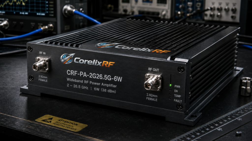
The CRF-PA-2G26.5G-6W represents thirty years of dedicated engineering refinement internally. It operates flawlessly from 2,000 up through 26,500 MHz continuously. Now consider this engineering fact. This module delivers a guaranteed 6W rated output power consistently. We specify a strict gain flatness of ±8dB maximum. Input VSWR stays below 2:1 across the entire frequency range. This robust input match minimizes interactions with your cascaded attenuators. Built-in protection circuits prevent catastrophic failure during severe mismatch events. It monitors temperature, detects over-current, and triggers VSWR alarm protection. Engineers get 36dB typical gain without fighting phantom bench reflections. It provides real engineering truth for your daily laboratory measurements. Harmonic suppression hits -15dBc, keeping spectrum analyzer screens completely uncluttered. Spurious emissions stay strictly below -60dBc across all operating modes. We measure all these parameters utilizing rigorous 50-ohm system conditions. This unit serves testing, communication, interference, and aviation control applications. Our hardware isolates your device under test from unpredictable sources. You capture actual data instead of fighting local bench parasitics. We build amplifiers fixing physical layer problems permanently for professionals.
CRF-PA-2G26.5G-6W Specifications
| Parameter | Specification Value | Unit |
| Frequency Range | 2,000 – 26,500 | MHz |
| Rated Output Power | 6 | W |
| Gain Flatness | ±8 | dB |
8. What are exact power and cooling requirements for reliable testing?
Consistent DC power dictates your final RF output signal purity. The CRF-PA-2G26.5G-6W demands a stable 18V/6A DC power supply. Listen closely to this detail. Voltage ripples directly modulate your carrier wave generating unwanted spurs. A high-quality linear bench supply prevents this specific noise injection. Proper air cooling dynamics prevent insidious thermal runaway conditions easily. This specific module utilizes an integrated forced air cooling method. You must maintain ambient operating temperatures between 0 and 40°C. Obstructing ventilation ports causes rapid internal heat sink saturation immediately. Thermal protection will trip, saving the amplifier from physical destruction. However, your ongoing automated test sequence will fail completely today. Proper rack mounting dictates adequate airflow for continuous reliable operation. Heat management dictates long-term reliability inside packed laboratory equipment racks. We machine our baseplates utilizing high-grade thermally conductive aluminum alloys. This efficiently pulls waste heat directly away from sensitive die. Industrial laboratories run multi-day reliability testing regimes without stopping once. Our thermal architecture handles these punishing continuous wave duty cycles. Engineers never worry about thermal shutdowns interrupting overnight automated scripts. You maintain absolute confidence in continuous high-power system testing operations.
9. How to correctly configure the test bench for 6W amplifiers?
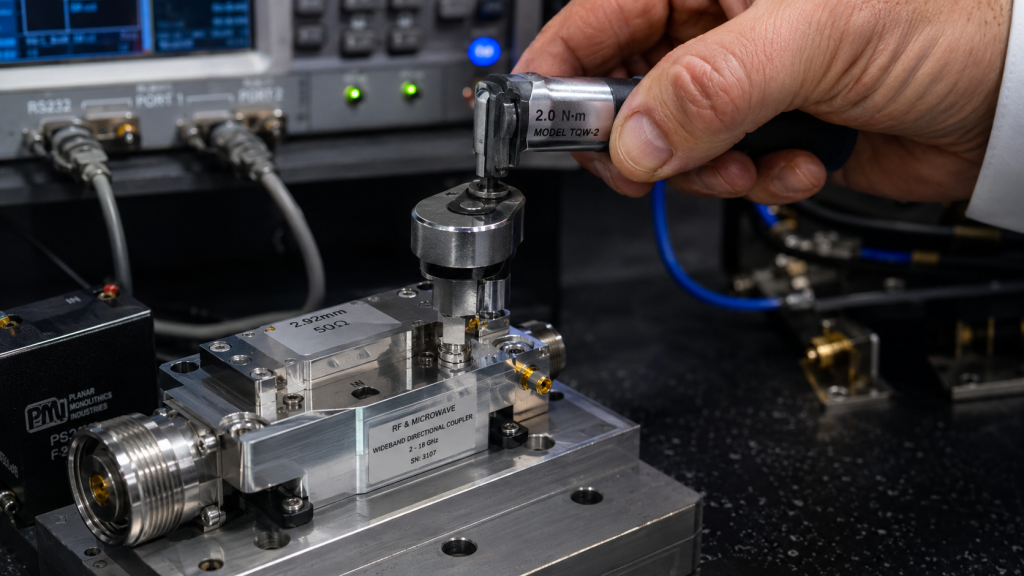
Physical connections require absolute precision in any high-frequency test laboratory. Always use calibrated torque wrenches on all 2.92mm-Female RF connectors. You might be wondering why. Over-tightening crushes delicate dielectric beads ruining high-frequency return loss measurements. Under-tightening leaves microscopic air gaps causing massive phase reflections continuously. Establish RS232 control interface communications before applying any RF drive. This allows active monitoring of internal diagnostic telemetry data constantly. Never operate power amplifiers without a proper 50-ohm load termination. Reflecting 6W back into the output stage creates dangerous voltages. The 240x160x50 mm package size requires stable mechanical bench support. Following these strict procedures guarantees accurate, repeatable B2B engineering results. Heavy coaxial cables strain delicate equipment bulkheads over extended time. Use proper strain relief loops when wiring your test bench. We provide detailed mechanical outline drawings for clear integration reference. Following factory installation guidelines prevents unnecessary mechanical hardware failures entirely. Our documentation helps system integrators build reliable final assemblies faster. Proper grounding techniques prevent ground loops from injecting low-frequency hum. You achieve pristine spectrum analyzer plots by respecting these hardware realities. Never compromise on basic mechanical assembly techniques inside your laboratory.
Bench Setup Checklist
| Configuration Step | Action Required | Expected Outcome |
| RF Connections | Use Torque Wrench | Optimal VSWR |
| Data Link | Connect RS232 | Telemetry Access |
| Output Port | Attach 50Ω Load | Prevent Damage |
10. What are long-term benefits of implementing calibrated hardware architectures?
System integrators require absolute consistency across multiple production testing cycles. Implementing strictly calibrated laboratory architectures provides repeatable engineering truth daily. The bottom line is this. You eliminate phantom errors caused by uncharacterized series test accessories. This drastically reduces expensive engineering troubleshooting time during system integration. Standardized calibration protocols guarantee data matches across different factory locations. Procurement engineers can confidently approve complex radar and communication sub-assemblies. CorelixRF designs components supporting these rigorous, high-value B2B testing environments. We supply specific test data and pattern files for review. Solid hardware foundations prevent software engineers from chasing fake hardware bugs. Investing in proper lab architecture yields massive long-term financial returns. Compliant hardware carrying CE, FCC, ISO 9001, and GJB 9001C certifications. This guarantees our manufacturing processes meet strict global quality frameworks. Optional forward and reverse power monitoring enables advanced system diagnostics. We support your technical expansion into complex millimeter-wave testing setups. Build your independent testing capabilities using proven industrial grade hardware. True engineering progress demands absolute trust in your fundamental measurement tools. You secure this trust by standardizing on rigorously verified RF components.
Properly calibrated microwave laboratory architectures prevent severe test data distortion. CorelixRF delivers the exact engineering truth system integrators demand continually. Our CRF-PA-2G26.5G-6W handles extreme broadband testing requirements flawlessly under pressure. Contact our technical team today for complete amplifier product datasheets. Stop fighting your bench and start capturing real performance metrics.
FAQ
Q1: What is gain flatness distortion?
Distortion occurs when uncalibrated series components cause extreme frequency response deviations across broadband measurements.
Q2: How does parasitic capacitance work?
It alters high-frequency impedance, creating unwanted phase shifts across transmission lines preventing flat frequency responses.
Q3: Why do engineers need RS232 interfaces? They allow active internal diagnostic monitoring during continuous automated laboratory testing running without operator intervention.
Q4: What causes high-band curve collapse?
Standing wave reflections bouncing between mismatched passive components destroy mathematical calibration planes above 18 GHz.
Q5: How do you fix mismatch uncertainty?
Use mathematically calibrated reference planes alongside highly robust power amplifier modules handling full band sweeps perfectly.
Turn this RF requirement into a quotable specification
Use this article as a starting point for a buildable RF specification. Before quoting, CorelixRF normally checks frequency range, output power, gain flatness, duty cycle, load mismatch, thermal path, control interface, enclosure limits and acceptance data.
- broadband SDR signal source – connect waveform or signal-source requirements to the RF front-end
- custom waveform support – define waveform, timing, bandwidth and control expectations before quoting
- RF configurator – turn frequency, power, thermal and interface requirements into a first configuration brief
- RFQ checklist – send the data buyers usually forget, including band, power, duty cycle, interface and test standard
- delivery documentation – check what documents can support incoming inspection, FAT review and long-term maintenance
- case studies – review similar engineering paths before sending an RFQ
- engineering contact – send the application notes, block diagram or target specification to engineering sales
For a faster review, send operating band, power target, modulation or waveform, antenna/load condition, cooling limit, mechanical envelope and target test standard through the RFQ or contact path.