

Understanding custom RF amplifiers involves mastering groundwork and prototype testing required for reliable system integration. Communication dropouts constantly plague defense contractors deploying counter-drone systems during critical missions. A failing signal compromises entire defense grids almost instantly. We engineer military-grade RF Amplifier solutions that guarantee uninterrupted broadband coverage. CorelixRF provides complete technical architectures built for extreme environments.
What Is the Design Groundwork for an RF Amplifier?
The design groundwork for an RF Amplifier dictates absolute baseline functionality. Engineers build mathematical models simulating power outputs before touching physical hardware. This initial planning prevents costly manufacturing failures down the line. We must define specific frequency bands and gain requirements early.
These models calculate theoretical thermal limits under maximum load conditions. Designers leverage advanced software mapping out potential impedance mismatches quickly.
Why Is Initial Modeling So Critical?
Initial modeling sets expectations regarding overall component behavior in dynamic environments. You save thousands by predicting voltage drops computationally. Here is the deal: accurate simulations prevent catastrophic hardware meltdowns during field deployment.
We measure predicted harmonic distortion against stringent military specifications daily.
- Simulations identify potential thermal hotspots accurately.
- Modeling predicts efficiency across target frequencies.
- Software highlights impedance matching requirements immediately.
Computer Simulation Basics
Engineers import scattering parameters into high-frequency structure simulator programs regularly. They establish virtual boundary conditions reflecting expected real-world operational constraints. Key Takeaway: Robust initial modeling guarantees your project begins with solid engineering foundations rather than costly guesswork.
| Simulation Type | Primary Goal | Output Metric |
| Thermal | Prevent overheating | Max Temperature |
| Electromagnetic | Verify signal integrity | S-Parameters |
| Mechanical | Ensure housing fit | Clearances |
| This simulation data provides a clear path forward toward hardware realization. |
How Do Engineers Plan the Architecture First?
Engineers plan the architecture first by mapping out necessary gain stages sequentially. An RF Amplifier requires careful balancing of gain and efficiency characteristics. Designers select specific gallium nitride transistors matching required bandwidth targets perfectly. We evaluate power consumption limits against available system supply voltages.
This architectural blueprint defines every major subsystem interaction clearly. Careful planning ensures seamless integration within larger communication platforms later.

Defining Power Output Needs
Output requirements dictate exactly which active components designers must select. You cannot simply chain random transistors hoping for stable signals. What is the real story?: unmatched components generate destructive reflected power quickly.
- Analyze peak envelope power demands.
- Determine necessary back-off for linearity.
- Specify maximum acceptable gain ripple.
Assessing Thermal Management
Heat dissipation determines long-term reliability inside confined military enclosures essentially. Designers calculate total power dissipated evaluating baseplate cooling requirements. Key Takeaway: Architectural planning defines physical boundaries securing consistent module performance across extreme operational temperatures.
| Cooling Method | Heat Dissipation | Complexity |
| Convection | Low | Simple |
| Conduction | High | Moderate |
| Liquid | Extreme | High |
| Proper thermal planning prevents premature component degradation during continuous operation. |
Why Is Pallet Testing Vital for an RF Amplifier?
Pallet testing validates core transistor performance inside a controlled environment. An RF Amplifier pallet represents a single operational gain stage physically. Engineers attach these pallets onto water-cooled fixtures for heavy stress evaluation. We push components past standard operating limits gathering raw empirical data.
This step exposes hidden parasitic oscillations missing from computer simulations. Real-world testing remains indispensable for military-grade component verification.
Gathering Real-World Data
Test benches capture actual efficiency metrics under varying load conditions. You quickly discover if theoretical models match physical reality closely. This is where it gets interesting: minor layout adjustments often yield massive efficiency improvements instantly.
- Measure raw saturated output power.
- Record efficiency at backed-off levels.
- Log input return loss accurately.
Performing Cascade Analysis
Engineers chain multiple pallets together predicting overall system gain mathematically. This analysis ensures proper drive levels reach final high-power stages reliably. Key Takeaway: Pallet testing bridges the gap between simulated theories and reliable hardware realities efficiently.
| Metric Measured | Target Value | Testing Method |
| Gain | >15 dB | Network Analyzer |
| Efficiency | >45% | Power Meter |
| VSWR | <1.5:1 | S-Parameter Test |
| Pallet verification establishes known good building blocks for complex assemblies. |
How Do Schematics Shape the Physical Layout?
Schematics shape the physical layout by defining electrical connections precisely. Your RF Amplifier relies upon optimized trace widths handling high currents safely. Layout engineers route sensitive radio signals away from noisy digital control lines. We maintain strict separation between differing ground planes ensuring stability.
Mechanical constraints dictate where input and output connectors must reside physically. A well-designed board minimizes parasitic capacitance improving overall high-frequency performance significantly.

Setting Dimensions and Connectors
Physical space inside military vehicles remains incredibly scarce always. You must shrink overall module footprints while maximizing output capabilities simultaneously. You might be wondering: how do we fit so much power into tiny spaces?
- Select low-profile coaxial connectors.
- Optimize component placement for density.
- Route traces avoiding mechanical interference.
Mechanical Fitment Checks
Software exports 3D models allowing designers a virtual assembly review process. They verify exact clearances between tall capacitors and metal enclosure lids carefully. Key Takeaway: Meticulous layout practices guarantee your circuits fit perfectly within their designated physical environments.
| Layout Factor | Design Constraint | Impact |
| Trace Width | Current handling | Thermal |
| Spacing | Voltage breakdown | Reliability |
| Grounding | Parasitic inductance | Stability |
| Accurate schematics prevent expensive mechanical revisions during final production phases. |
What DC Power and Control Elements Are Needed?
DC power elements provide necessary energy fueling radio frequency generation. An RF Amplifier draws substantial current requiring robust regulation circuitry internally. We implement sequenced biasing networks protecting sensitive gallium nitride transistors from destruction. Proper control logic shuts down modules during severe temperature overloads automatically.
Telemetry interfaces report real-time operating metrics back toward master controllers constantly. These features transform dumb amplifiers into smart system components seamlessly.
Integrating Power Delivery
High-power modules demand exceptionally clean voltage rails for maximum linearity. You cannot feed noisy switching supply voltages directly into amplifier bias pins. Ready for the good part?: custom linear regulators filter out unwanted ripple entirely.
- Implement low-dropout voltage regulators.
- Add extensive bypass capacitance networks.
- Design high-current bus bar routing.
Control Logic Integration
Microcontrollers manage startup sequences preventing dangerous voltage spikes effectively. They monitor reflected power instantly disabling transmission if antennas break. Key Takeaway: Intelligent control electronics safeguard your hardware investments extending overall operational lifespans dramatically.
| Feature | Function | Benefit |
| Sequencer | Drain/Gate timing | Protects GaN |
| Temp Sensor | Monitors heat | Prevents fire |
| Current Limit | Caps draw | Stops shorts |
| Integrated control systems deliver unparalleled reliability during chaotic operational scenarios. |
How Do We Build the First RF Amplifier Prototype?
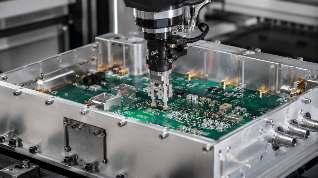
Building the first prototype involves transforming digital designs into physical hardware. Assembling an RF Amplifier requires extreme precision handling microscopic surface mount components. Technicians apply specialized solder pastes ensuring void-free thermal attachments beneath power transistors. We mount populated circuit boards into precision-milled aluminum housings carefully.
Quality control inspections happen after every single assembly step systematically. Catching manufacturing defects early saves countless hours during subsequent testing phases.
Transitioning from Layout to Build
Procurement teams source critical components experiencing long lead times aggressively. You need absolute supply chain reliability avoiding last-minute part substitutions. Let that sink in: one wrong capacitor value ruins an entire build completely.
- Verify bill of materials accuracy.
- Inspect bare circuit boards microscopically.
- Audit component reels before loading.
Quality Control During Assembly
Automated optical inspection machines scan soldered boards flagging potential bridging issues automatically. X-ray systems examine hidden solder joints beneath large transistor packages thoroughly. Key Takeaway: Strict prototype assembly protocols ensure any subsequent test failures stem from design flaws rather than manufacturing errors.
| Inspection Step | Technology Used | Target Defect |
| Solder Paste | 3D SPI | Insufficient volume |
| Component | AOI | Misalignment |
| Hidden Joint | X-Ray | Voiding |
| Rigorous assembly standards eliminate frustrating variables during initial prototype evaluations. |
What Is the Baseline Performance Testing Process?
Baseline testing establishes exactly how the raw prototype functions initially. Every RF Amplifier undergoes rigorous characterization before any manual tuning begins. Engineers connect modules onto vector network analyzers sweeping frequencies across specified bands. We document initial small-signal gain profiles discovering unexpected resonance peaks quickly.
Power meters measure absolute output levels confirming basic energy amplification capabilities. This data forms a foundational benchmark judging all future tuning efforts against.
Measuring Initial Output
Initial sweeps reveal if the hardware meets basic architectural expectations basically. You often see slight deviations from computer models due to parasitic elements. Why does this matter?: these deviations guide engineers deciding where manual tuning remains necessary.
- Sweep small signal gain.
- Measure un-tuned return loss.
- Verify baseline DC power draw.
Verifying Gain Flatness
A flat response ensures signals pass without distortion across wide bandwidths evenly. Engineers identify specific frequencies requiring extra compensation networks carefully. Key Takeaway: Comprehensive baseline testing illuminates exact performance gaps needing expert engineering attention immediately.
| Parameter | Initial Goal | Test Equipment |
| S21 (Gain) | Near target | Network Analyzer |
| Pout | Within 3dB | Power Meter |
| Quiescent Id | Matches model | Multimeter |
| Accurate baseline metrics provide a roadmap for all subsequent tuning operations. |
How Do We Tune a Prototype RF Amplifier?
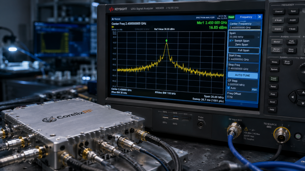
Tuning a prototype requires incredible patience and deep electromagnetic understanding. An RF Amplifier often needs physical modifications improving high-frequency impedance matching networks. Engineers solder tiny copper flakes adjusting capacitance along transmission lines dynamically. We monitor spectrum analyzers continually watching performance metrics change instantly.
This hands-on process optimizes power transfer between cascading amplifier stages perfectly. Skilled technicians transform mediocre prototypes into highly efficient military-grade transmitters successfully.
Identifying Performance Gaps
Engineers compare baseline test data against strict customer requirement documents meticulously. You isolate specific frequency bands where power drops below acceptable minimums. Look at it this way: tuning bridges the gap separating theory from reality.
- Locate mismatched frequency zones.
- Calculate necessary phase shifts.
- Prepare copper tuning elements.
Adjusting Matching Networks
Moving tuning pads fractions of a millimeter alters resonant frequencies drastically. Technicians secure optimal pad locations using permanent high-temperature solder carefully. Key Takeaway: Expert manual tuning extracts maximum possible performance from your established circuit layouts reliably.
| Tuning Action | Intended Effect | Trade-off |
| Add Capacitance | Lower resonance | Reduced bandwidth |
| Add Inductance | Shift phase | Increased loss |
| Adjust Bias | Improve linearity | Worse efficiency |
| Careful tuning balances competing performance metrics achieving optimal overall results. |
Why Are Environmental Stress Tests Conducted?
Stress tests guarantee survival within harsh military operational environments consistently. A deployed RF Amplifier faces extreme temperature swings and brutal physical shocks. We place prototypes inside thermal chambers cycling from freezing cold to scorching heat. Engineers monitor radio frequency performance continuously while ambient conditions fluctuate wildly.
Vibration tables simulate transport across rugged terrain or missile launch profiles accurately. Components failing these stress tests require immediate redesign preventing catastrophic field failures.
Thermal Chamber Validations
Heat alters semiconductor characteristics shifting amplifier gain profiles noticeably over time. You must verify control circuits compensate for these temperature-induced fluctuations automatically. But wait, there is more: extreme cold causes mechanical solder joints to fracture unexpectedly.
- Cycle temperatures rapidly continuously.
- Monitor gain variations constantly.
- Verify thermal shutdown thresholds.
Vibration and Shock Trials
Mechanical shock tests expose weak mounting points breaking heavy components loose violently. Conformal coatings protect delicate traces from moisture ingress during humidity trials. Key Takeaway: Rigorous environmental testing ensures your communications hardware survives the absolute worst battlefield conditions imaginable.
| Test Environment | Military Standard | Simulated Condition |
| Temp Cycle | MIL-STD-810 | Desert to Arctic |
| Vibration | MIL-STD-810 | Helicopter transport |
| Humidity | MIL-STD-810 | Jungle deployment |
| Surviving these trials validates the inherent ruggedness engineered into every design. |
How Is the Final RF Amplifier Design Documented?
Final documentation translates tuned prototypes into repeatable mass manufacturing instructions. Every RF Amplifier revision gets captured inside strict version control software systems. Engineers update original schematics reflecting all copper tuning pads added manually earlier. We rewrite assembly procedures detailing specific soldering techniques required for difficult parts.
Test engineers finalize automated testing scripts ensuring production units match prototype performance. Comprehensive documentation eliminates tribal knowledge securing long-term product lifecycle stability.
Capturing Tuning Adjustments
Draftsmen convert manual copper pad placements into permanent circuit board trace revisions. You eliminate human tuning errors by hardcoding successful modifications directly into layouts. Now, consider this: repeatable manufacturing depends entirely upon accurate engineering documentation.
- Update PCB layout files.
- Revise component values officially.
- Release new BOM versions.
Handing Over to Production
Engineers train manufacturing staff regarding critical assembly nuances specifically. They establish final pass/fail test limits based upon statistically significant prototype data. Key Takeaway: Thorough documentation processes guarantee consistent military-grade quality across thousands of production units.
| Document Type | Purpose | User |
| Schematic | Circuit definition | Engineering |
| BOM | Parts list | Procurement |
| Test Proc | Verification | QC Team |
| Robust documentation transfers intricate engineering knowledge into scalable manufacturing power. |
Start Your Project Today
CorelixRF manufactures complete military-grade RF architectures solving your toughest connectivity problems. When communication dropouts threaten critical defense missions, we provide continuous broadband coverage eliminating vulnerabilities. Our proven engineering expertise bridges complex theoretical designs with highly reliable field performance seamlessly. If you demand sustained output without power degradation, contact us today exploring engineering-driven manufacturing solutions. CorelixRF stands as your dedicated partner pushing boundaries across the electromagnetic spectrum continuously.
FAQ
Q1: Can I integrate these modules into existing counter-drone systems?
Yes, you can integrate them seamlessly. Our modules support standard RS422 control interfaces alongside multi-waveform compatibility enabling straightforward system-level architecture upgrades.
Q2: What’s the best way to manage heat in high-power applications?
Integrating aluminum heat-sinks remains highly effective. We optimize thermal planning early determining conduction baseplate requirements preventing premature component degradation under sustained loads.
Q3: How do I know if my project requires custom frequency bands?
Analyze your specific operational environment carefully. If standard bands suffer heavy interference or fail targeting unique threats, our engineering team customizes bandwidths matching exact mission parameters.
Q4: Can I expect stable power across the entire frequency range?
Absolutely, output remains incredibly stable. We guarantee less than 1.5dB gain flatness across continuous bands validating this performance through stringent baseline testing protocols.
Q5: What’s the best method for verifying military-grade quality?
Demand rigorous environmental stress testing always. We expose prototypes toward extreme thermal cycling plus vibration trials ensuring survival within the harshest battlefield conditions imaginable.
Authorized RF engineering and compliance review
For regulated RF systems, this page should be used as an engineering and compliance review path, not as a public deployment checklist. CorelixRF starts with authorization status, operating region, frequency plan, output limit, antenna interface, safety controls, thermal limits and acceptance documents.
- RFQ checklist – send the data buyers usually forget, including band, power, duty cycle, interface and test standard
- delivery documentation – check what documents can support incoming inspection, FAT review and long-term maintenance
- quality and certification review – review the quality and compliance evidence before the project moves into procurement
- RF front-end platform – compare the RF chain as a system instead of selecting one isolated module
- RF configurator – turn frequency, power, thermal and interface requirements into a first configuration brief
- case studies – review similar engineering paths before sending an RFQ
- engineering contact – send the application notes, block diagram or target specification to engineering sales
This keeps the discussion inside lawful, authorized RF programs while still giving procurement teams a clear way to request amplifier, antenna, SDR source, documentation and factory review.
RF Amplifier Integration Review Path
For custom RF amplifier projects that involve site constraints, front-end fit or authorized system integration, compare RF power amplifier platform options with RF front-end platform planning before sending requirements through the RF inquiry form. CorelixRF can review frequency band, output power, duty cycle, antenna/load condition, control interface and validation evidence before quotation.