
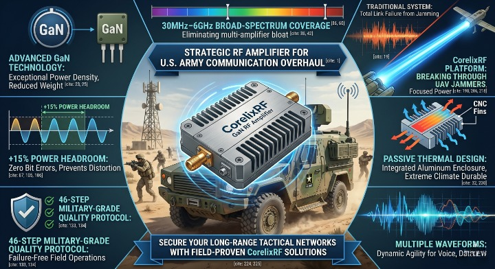
Why Do Modern Military Networks Experience Signal Degradation?
Field operations face relentless electronic interference from sophisticated state actors utilizing tactical jamming machinery. This congestion corrupts standard communication links and leaves deep frontline units dangerously isolated.
But here’s the kicker…
Standard commercial hardware cannot tolerate this intense electromagnetic pressure without experiencing catastrophic thermal breakdown.
- High-density signal jamming disrupts traditional command networks.
- Atmospheric thermal changes degrade raw transmitter output efficiency.
- Antenna impedance mismatches cause severe power reflection issues.
How Do High-Power Platforms Restore Tactical Links?
Deploying an advanced RF Amplifier architecture resolves these communication bottlenecks by boosting weak signals above the adversary jamming threshold. This approach ensures that vital tactical telemetry cuts through heavy battlefield noise smoothly.
What’s the real story? True operational security requires solid hardware capability that performs perfectly under extreme combat stress.
- High-power GaN modules supply extended transmission range coverage.
- Linear power delivery preserves complex digital signal integrity.
- Fast switching speeds support dynamic frequency hopping protocols.
Key Takeaway
Integrating ruggedized power transmission hardware preserves critical data infrastructure and protects personnel during high-stress electronic warfare engagements.
| Operational Challenge | Traditional System Impact | CorelixRF Platform Solution |
|---|---|---|
| Electronic Jamming | Total Link Failure | Signal Penetration |
| Thermal Overheating | Power Degradation | Continuous Max Output
| Signal Distortion | Data Packet Loss | Linear Performance
The comparative matrix highlights how upgrading your transmission hardware mitigates critical system failures during contested field deployments.
How Does GaN Technology Transforming Defense RF Chains?
A modern RF Amplifier relies on Gallium Nitride technology to achieve exceptional power density within compact tactical enclosures. This semiconductor innovation allows defense communication systems to generate massive output while consuming minimal vehicle battery power. You can immediately minimize your logistical footprint by replacing legacy traveling-wave tubes with solid-state components. CorelixRF leverages this specific technology to design broad-spectrum modules that deliver continuous coverage across critical tactical frequencies.
What Makes Gallium Nitride Superior to Legacy Silicon?
Gallium Nitride operates at significantly higher voltages and thermal thresholds than traditional silicon components. This allows engineers to extract massive wattage from a fraction of the physical space.
Ready for the good part?
Your systems will experience reduced heat dissipation needs and decreased power supply strain during long missions.
- Higher breakdown voltages enable extreme output wattage levels.
- Enhanced thermal conductivity keeps internal junction temperatures low.
- Reduced parasitic capacitance permits wider operational frequency bands.
### How Does GaN Power Improve Wideband System Agility?
Wideband systems can sweep across multi-octave frequencies without requiring bulky electromechanical tuning networks. This rapid frequency agility keeps your tactical transmissions ahead of automated enemy interception systems.
This is where it gets interesting… Achieving this wide bandwidth typically meant sacrificing total output efficiency until solid-state GaN arrived.
- Continuous 30MHz–6GHz coverage eliminates multi-amplifier system bloat.
- Flat gain performance removes the need for complex digital equalization.
- Fast pulsing capabilities support modern advanced radar configurations.
Key Takeaway
Transitioning your defense infrastructure to Gallium Nitride modules maximizes transmission efficiency while shrinking system weight and power requirements.
| Semiconductor Metric | Legacy Silicon Hardware | Advanced GaN Platforms |
|---|---|---|
| Power Density | Low to Moderate | Extremely High |
| Max Frequency | Limited Bandwidth | Ultra-Wideband
| Thermal Threshold | Moderate Limits | High Temperature
Reviewing these semiconductor metrics reveals why modern defense integrators consistently choose solid-state GaN for ruggedized communication nodes.
Can Broadband Coverage Eliminate Multiple Tactical Radio Modules?
Every battlefield RF Amplifier module must cover expansive frequency ranges to support diverse joint-agency communication protocols. Splitting your operations across separate single-band transmitters creates severe logistical bottlenecks and increases vehicle weight. You can simplify your hardware deployment by using a unified full-band platform that manages multiple waveforms simultaneously. CorelixRF designs these single-enclosure wideband systems to streamline tactical field operations for modern system integrators.

Why Is Multi-Band Integration Essential for Ground Forces?
Modern military operations demand real-time data sharing across infantry, armored assets, and supportive airborne drone assets. A fragmented radio setup delays critical communication loops and complicates field maintenance routines.
But here’s the kicker… Consolidating these channels requires sophisticated impedance matching networks that prevent internal signal reflection damage.
- Single-platform operation supports VHF, UHF, and L-band waveforms.
- Reduced hardware footprint frees up vital space inside armored vehicles.
- Simplified cabling networks minimize point-of-failure risks in combat zones.
How Do Wideband Modules Maintain Strict Gain Flatness?
Maintaining consistent output levels across an ultra-wide frequency spectrum prevents dangerous dropouts during automated frequency hopping maneuvers. Advanced internal feedback loops dynamically balance gain variations without human intervention.
What’s the real story? Poor gain flatness can cause your signal to drop below readable levels on specific channels.
- Less than 1.5dB variation across the entire spectrum ensures stability.
- Automated bias adjustment protects the system against sudden voltage spikes.
- Optimized VSWR performance guarantees efficient power transfer to antennas.
Key Takeaway
Deploying a single wideband power platform eliminates heavy multi-module weight penalties while securing reliable cross-agency communication channels.
| Spectrum Segment | Supported Waveforms | System Output Stability |
|---|---|---|
| 30MHz — 512MHz | Tactical VHF/UHF Voice | Confirmed <1.5dB Flatness |
| 500MHz — 2000MHz | High-Speed Data Links | Confirmed <1.5dB Flatness
| 2000MHz — 6000MHz | Drone Control & C-UAS | Confirmed <1.5dB Flatness
This frequency mapping demonstrates how a unified wideband module sustains consistent power across all critical defense bands.
What Determines Thermal Stability in High-Power RF Design?
An operational RF Amplifier produces significant thermal energy that must be managed to prevent power degradation. When operating in extreme desert climates, passive cooling structures often fail to protect internal components from melting. You need an aggressive thermal management architecture that balances heat dissipation with ruggedized structural sealing. CorelixRF utilizes advanced simulation software to engineer integrated aluminum enclosures that pull heat away from critical junctions.
### How Does Heat Compromise Tactical Transmission Power?
Uncontrolled thermal build-up causes power slump, which reduces your total transmission range when you need it most. High temperatures accelerate component aging and increase the risk of unexpected field failure during operations.
Ready for the good part?
Proper thermal engineering prevents these power drops and extends system life.
- Thermal saturation reduces overall transistor efficiency by fifteen percent.
- Excessive heat alters internal impedance matching values over time.
- Prolonged high-temperature exposure weakens delicate internal wire bonds.
What Engineering Methods Ensure Continuous CW Performance?
Continuous-wave operation requires high-grade aluminum heat sinks combined with heavy-duty thermal interface materials. This setup creates a low-resistance path that channels heat away from the sensitive GaN dies.
This is where it gets interesting… Many manufacturers rely on fans that fail in dusty combat environments, but passive rugged designs endure.
- CNC-machined aluminum housings optimize natural convective airflow patterns.
- Advanced phase-change materials eliminate microscopic air gaps between components.
- Integrated thermal sensors automatically trigger protective throttle modes if needed.
Key Takeaway
Investing in advanced thermal management hardware protects your communication nodes from heat-induced power loss during continuous long-range operations.
| Coolant Methodology | Environmental Suitability | Long-Term Reliability |
|---|---|---|
| Forced Air (Fans) | Low (Dust Prone) | Moderate to Low |
| Liquid Cooled Loops | High (Complex Integration) | High Maintenance |
| Integrated Passives | High (Deploys Anywhere) | Maximum Durability |
|
The cooling methodology evaluation proves that integrated passive structures offer the best reliability for remote defense systems.
Why Is Power Headroom Critical for Electronic Countermeasures?
A defense RF Amplifier system must provide sufficient power headroom to handle complex, high-amplitude digital modulation formats. Without this extra power margin, your signals will clip and cause severe data corruption during electronic attack maneuvers. You can prevent this distortion by specifying components that include at least fifteen percent power redundancy. CorelixRF builds extra power margin into every RF Amplifier module to protect your signal integrity against sudden peak loads.
What Is Power Headroom and Why Do Systems Need It?
Power headroom is the unused capability that sits above your standard operating wattage level. This safety buffer prevents peak signals from driving the transmission module into heavy distortion.
But here’s the kicker… Many suppliers rate their hardware at maximum saturation, leaving zero margin for complex operational waveforms.
- Redundancy prevents signal clipping during high-speed data bursts.
- Extra margin accommodates sudden impedance changes from damaged antennas.
- System components run cooler when operating below their absolute limits.
How Does Power Margin Protect Complex Modulation Formats?
Modern signal waveforms like OFDM require highly linear amplification to preserve their intricate phase and amplitude characteristics. Driving an under-powered system into saturation distorts these signals and renders them unreadable by receiving nodes.
What’s the real story? Maintaining clean linearity across high peaks requires conservative hardware ratings and premium internal components.
- Clean amplification protects delicate phase values across broad bandwidths.
- Low error vector magnitude scores ensure rapid data packet decoding.
- Reduced spectral regrowth prevents interference with adjacent communication channels.
Key Takeaway
Specifying a fifteen percent power headroom margin guarantees clean data transmission and protects hardware from clipping distortion during electronic warfare.
| Headroom Margin | Link Quality (OFDM) | Transistor Stress Level |
|---|---|---|
| 0% (Saturated) | Severe Data Corruption | Maximum High Stress |
| 5% — 10% | Moderate Packet Loss | Elevated Operational Strain |
| 15%+ (Optimized) | Zero Bit Errors |
| Low Safe Operation
This performance matrix shows that keeping a fifteen percent power margin protects complex tactical data streams from distortion.
How Do Multi-Waveform Signals Affect Tactical Link Distance?
A multi-waveform RF Amplifier must process diverse signal types without losing output efficiency or reducing transmission range. When transitioning from simple voice communications to high-bandwidth video streams, legacy hardware often experiences massive range drops. You must employ adaptive biasing systems that adjust internal parameters based on the active waveform type. CorelixRF incorporates smart power tracking systems that optimize efficiency across voice, radar, and jamming signals.
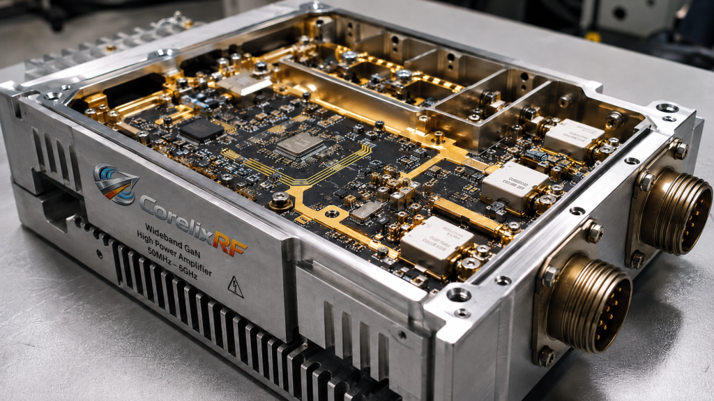
Why Do Different Waveforms Demand Specific Linearity?
Simple frequency-modulated signals can run efficiently on non-linear hardware without causing signal distortion issues. However, advanced tactical data links require high linearity to keep data moving across long distances.
Ready for the good part? Smart internal monitoring systems allow a single piece of hardware to manage both signal categories efficiently.
- Constant amplitude signals maximize raw DC-to-RF power conversion efficiency.
- Variable amplitude signals require precise back-off adjustments to limit distortion.
- Adaptive bias tracking changes current levels based on real-time signal demands.
What Technologies Maintain Link Range Under Heavy Jamming?
Sustaining clear data links through electronic jamming requires a combination of high raw output power and advanced error correction. The amplification system must deliver this energy cleanly without adding internal harmonic noise.
This is where it gets interesting… Adversaries focus their jamming energy on weak harmonic frequencies, meaning your system must remain pure.
- Low harmonic distortion keeps your transmission energy focused on the main channel.
- Fast settling times allow seamless operation with ultra-rapid frequency-hopping radios.
- High dynamic range lets the receiver catch weak signals right next to strong jamming fields.
Key Takeaway
Using intelligent multi-waveform hardware preserves your long-range tactical links even when operating under heavy enemy jamming conditions.
| Waveform Type | Linearity Requirement | Link Range Retention |
|---|---|---|
| Standard Voice FM | Low Structural Priority | Excellent Range Balance |
| High-Speed OFDM | Critical Maximum Priority | Dependent on Linearity |
| Pulsed EW Jamming | Moderate Operational Balance | Targeted High Energy
The waveform compatibility index highlights why maintaining linearity is essential for high-speed tactical data networks.
What Quality Protocols Guarantee Failure-Free Field Operations?
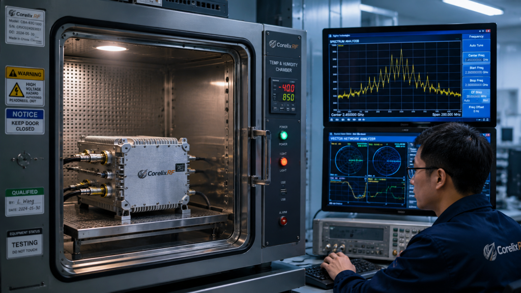
A reliable RF Amplifier must undergo rigorous environmental stress screening before deploying into active military theater zones. If a supplier skips basic vibration testing, their hardware can fail during high-speed cross-country transport operations. You should partner with manufacturers that follow comprehensive, multi-step quality protocols to ensure zero field failures. CorelixRF implements a strict 46-step military-grade quality testing process to verify every production lot.
### Why Use a 46-Step Military Quality Protocol?
Standard electronic testing protocols fail to catch intermittent material defects that cause field failures under stress. A multi-phase testing process tracks component performance from raw material arrival through final system assembly.
But here’s the kicker… While many component vendors stop at basic functional checks, true reliability requires extensive stress screening.
- Incoming material inspections isolate counterfeit components before they reach assembly lines.
- Automated optical inspections verify correct component placement on every circuit board.
- Automated testing eliminates human error from the final hardware verification process.
How Do Extreme Environmental Tests Prove Field Readiness?
Thermal cycling and physical vibration testing simulate years of harsh field deployment inside a controlled laboratory environment. These evaluations force weak connections to fail early in the factory rather than in the field.
What’s the real story? True reliability means testing hardware beyond its rated operational limits to find hidden vulnerabilities.
- Multi-day thermal baking uncovers latent semiconductor defects before final packaging.
- Random vibration tables simulate the harsh mechanical stress of tracked combat vehicles.
- Environmental chamber testing ensures performance drops remain within allowed tolerances.
Key Takeaway
Verifying your communications hardware through strict 46-step quality protocols eliminates unexpected system failures during critical field missions.
| Quality Assurance Phase | Specific Test Metric | Field Failure Prevention |
|---|---|---|
| Phase 1: Incoming Inspection | Material Purity Check | Counterfeit Component Exclusion |
|
| Phase 2: Stress Screening | Multi-Hour Burn-In | Early Component Failure Detection
|
| Phase 3: Environmental Lab | Temperature Cycling | Climate Vulnerability Elimination
|
This quality protocol breakdown shows how rigorous factory testing ensures reliable field performance in harsh environments.
How Can Custom Packaging Solve Tight Enclosure Constraints?
Your specialized RF Amplifier needs to fit into tight tactical spaces without requiring extensive rewiring of the vehicle chassis. When standard off-the-shelf enclosures fail to meet your space limits, custom mechanical packaging becomes essential. You can speed up your system integration by choosing custom blind-mate connections and tailored thermal profiles. CorelixRF provides complete custom engineering services to shape power modules around your specific chassis layouts.
Why Is Custom Enclosure Engineering Essential for Systems Integration?
Modern armored vehicles and small unmanned aircraft have strict size, weight, and power limits that standard products cannot meet. Forcing a square module into a complex space creates cabling problems and limits airflow.
Ready for the good part? Custom housings allow you to combine multiple RF functions into a single compact chassis.
- Tailored dimensions utilize irregular unassigned cavities inside modern airframes.
- Custom connector placement shortens internal high-frequency coaxial cable runs.
- Integrated mounting features speed up installation on vehicle production lines.
How Do Blind-Mate Connectors Speed Up Field Maintenance?
Blind-mate connectors allow technicians to replace failed modules quickly without manually disconnecting delicate coaxial cables. Slide-in mounting racks automatically align high-frequency interfaces for secure connections every time.
This is where it gets interesting… Reducing maintenance time keeps your vital communication assets online during active operations.
- Quick-disconnect hardware cuts module swap times down to under two minutes.
- Self-aligning pins protect expensive coaxial interfaces from technician damage during field swaps.
- Environmental seals prevent dust moisture contamination during quick field replacements.
Key Takeaway
Using custom enclosure packaging helps you meet tight size and weight limits while streamlining field maintenance routines.
| Housing Profile Option | Spatial Footprint Savings | Field Maintenance Speed |
|---|---|---|
| Standard Standard Casing | Zero Spatial Savings | Standard Manual Bolt-In |
| Tailored Form Factor | 30% Space Reduction | Fast Integration |
| Blind-Mate Integrated | 40% Space Reduction | Slide-In Module Swap
The housing configuration table illustrates how custom engineering optimizes space and speeds up field maintenance.
What Calibration Protocols Maximize High-Frequency Link Accuracy?
Every defense RF Amplifier requires precise initial factory calibration to ensure consistent power output across wide operating bands. Without accurate calibration data, your transmitters can produce uneven signal levels that degrade overall link quality. You can maintain stable communication ranges by choosing modules that feature integrated digital calibration tables. CorelixRF uses high-precision vector network analyzers to program accurate calibration data into every module.
Why Is Factory Calibration Critical for High-Frequency Output?
Advanced semiconductor components show natural performance variations across broad operating frequencies and temperatures. Automated factory calibration maps these variations and stores real-time correction profiles directly inside the hardware.
But here’s the kicker… Uncalibrated hardware can experience significant power drops at higher frequencies, reducing your link range.
- Automated mapping eliminates gain variations across the entire spectrum.
- Temperature tracking loops protect your signal levels in extreme desert or arctic conditions.
- Internal power detection sensors provide accurate output telemetry to the system controller.
How Do Modern Vector Analyzers Verify Signal Purity?
Advanced vector analyzers measure phase and amplitude performance across the entire frequency band to confirm strict specifications. This deep analysis ensures your hardware will not generate unwanted harmonic interference in the field.
What’s the real story? Clean signal performance prevents your transmitter from disrupting nearby friendly radio networks.
- Precise phase matching supports advanced multi-antenna beamforming arrays.
- Group delay calibration keeps high-speed digital data streams perfectly aligned.
- Return loss measurement ensures efficient energy transfer to your antenna.
Key Takeaway
Using precision-calibrated power amplification hardware ensures reliable signal accuracy and consistent link ranges across changing field environments.
| Testing Equipment Used | Measurement Parameter | Link Integrity Impact |
|---|---|---|
| Vector Network Analyzer | Phase & Gain S-Parameters | Flat Output Delivery |
| Spectrum Analyzer | Harmonic Output Spikes | Pure Clean Waveforms
| Digital Oscilloscope | Signal Modulation Purity | Accurate Data Transfer
This calibration hardware matrix highlights how rigorous lab testing translates directly into clean, reliable field communications.
How Do System Integrators Protect Vital Communications Against Modern UAV Jammers?
A ruggedized RF Amplifier system provides the necessary output power to break through modern drone-stopping electronic jamming barriers. When frontline infantry units face automated airborne threats, reliable communication links are vital for coordinating defensive maneuvers. You must integrate high-power wideband systems that secure communication lines during electronic attacks. CorelixRF develops full-band power systems designed to maintain link security for global defense integrators.
Why Must Ground Links Resist Modern UAS Jamming Systems?
Modern unmanned systems carry agile electronic jamming packages that target standard military communication bands. Unprotected communication networks can easily lose connection, leaving forward troops isolated.
Ready for the good part? High-efficiency solid-state amplification allows your tactical networks to overpower jamming signals and maintain stable data links.
- Focused power output keeps critical command links open during electronic attacks.
- Wide frequency coverage supports fast frequency-hopping to avoid active jammers.
- Fast pulsing capability allows simultaneous communication and drone detection operations.
How Do Integrated RF Solutions Simplify Modern Defense Logistics?
Using integrated power modules reduces system complexity by combining filtering, amplification, and switching into one rugged enclosure. This unified design shortens your assembly time and simplifies spare parts management in the field.
This is where it gets interesting… Fewer cable connections mean lower signal loss and fewer failure points during heavy field usage.
- Standard interfaces speed up integration with your existing tactical radio platforms.
- Sealed weather-proof enclosures protect sensitive electronics from dust, sand, and rain.
- Unified power rails reduce the need for complex internal voltage regulation.
Key Takeaway
Deploying integrated wideband power modules protects your tactical communication lines against modern automated jamming threats.
| Operational Threat | Impact on Standard Radios | Integrated Platform Protection |
|---|---|---|
| UAS-Mounted Jammer | Total Loss of Line-of-Sight | Continuous Data Flow |
| Frequency Sweeping | Intermittent Signal Drops | Fast Frequency Hopping
| High Signal Noise | Dropped Data Packets | High-Linearity Links
This threat mitigation matrix highlights how upgrading your power systems protects tactical data links from modern jamming threats.
Summary of Technical Realities
Maintaining stable tactical communications in electronic warfare environments requires ruggedized high-power hardware. This article discussed how solid-state GaN technology, wideband coverage, 46-step quality protocols, and custom packaging protect links against modern jamming threats. Our factory designs and manufactures complete high-power amplification platforms that deliver reliable performance in extreme combat zones. If you are looking to secure your long-range tactical networks against modern electronic threats, contact us today to review your specific requirements. We remain dedicated to engineering the future of high-power defense communications with field-proven reliability and performance.
Frequently Asked Questions
Can I deploy these wideband components into existing military enclosures without redesigning my system layout?
Yes, you can easily deploy these modules because our custom engineering team designs enclosures to match your exact dimensions and connection requirements. This drop-in compatibility reduces your development costs and speeds up vehicle upgrades.
### What’s the best way to maintain continuous output power during high-temperature desert operations?
The best approach is to use our integrated passive cooling housings, which feature CNC-machined aluminum structures that keep internal junction temperatures low without relying on failure-prone cooling fans. This design ensures reliable, continuous-wave performance in the harshest climates.
How do I know if my complex data signals will suffer from distortion during high-power amplification?
You can confirm signal purity by checking our low error vector magnitude metrics and our strict less than 1.5dB gain flatness specifications. Every module includes built-in power headroom to handle high-amplitude data bursts without signal clipping.
Can I use these solid-state amplification modules for both communication links and electronic warfare applications?
Yes, you can use them for both roles because our wideband platforms operate across a continuous 30MHz to 6GHz spectrum that supports voice, data, and signal jamming waveforms. This multi-role capability simplifies your system design and saves valuable vehicle space.
How do you ensure consistent performance across large production lots?
We guarantee consistent performance by putting every module through our strict 46-step military quality protocol, which includes automated circuit inspection, thermal baking, and physical vibration testing. This rigorous process ensures that every production unit matches our official engineering specifications.
Authorized RF engineering and compliance review
For regulated RF systems, this page should be used as an engineering and compliance review path, not as a public deployment checklist. CorelixRF starts with authorization status, operating region, frequency plan, output limit, antenna interface, safety controls, thermal limits and acceptance documents.
- RFQ checklist – send the data buyers usually forget, including band, power, duty cycle, interface and test standard
- delivery documentation – check what documents can support incoming inspection, FAT review and long-term maintenance
- quality and certification review – review the quality and compliance evidence before the project moves into procurement
- RF front-end platform – compare the RF chain as a system instead of selecting one isolated module
- RF configurator – turn frequency, power, thermal and interface requirements into a first configuration brief
- case studies – review similar engineering paths before sending an RFQ
- engineering contact – send the application notes, block diagram or target specification to engineering sales
This keeps the discussion inside lawful, authorized RF programs while still giving procurement teams a clear way to request amplifier, antenna, SDR source, documentation and factory review.
Tactical RF Amplifier Engineering Path
For rugged communication networks, move from concept to specification by reviewing RF power amplifier platforms, custom amplifier options, and the required RF front-end interface.