The latest advances in RF Power Amplifier design involve the integration of wide-bandgap semiconductors like Gallium Nitride (GaN), advanced linearization through digital pre-distortion, and high-efficiency architectures such as Envelope Tracking. Modern wireless communication demands higher data rates and broader coverage, yet legacy hardware frequently suffers from excessive energy waste and signal degradation. These inefficiencies create a significant bottleneck for 5G, satellite communications, and high-performance radar systems that you may be developing.
For engineers, the challenge is twofold: heat and size. Traditional amplifiers dissipate significant power as heat, requiring bulky cooling systems that prevent miniaturization in your designs. Furthermore, maintaining signal linearity at high power levels often feels like a losing battle against physics, leading to distorted transmissions and increased operational costs. Recent breakthroughs in materials science and circuit architecture are redefining the limits of performance. By leveraging wide-bandgap semiconductors, implementing advanced linearization, and adopting integrated module designs, the modern RF Power Amplifier is becoming smaller, cooler, and significantly more powerful.
1. Why is GaN revolutionizing the RF Power Amplifier?
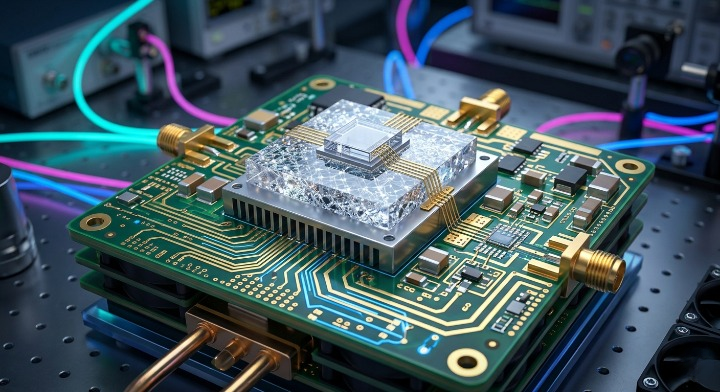
Gallium Nitride (GaN) is revolutionizing the industry because it allows an RF Power Amplifier to operate at much higher power densities and thermal efficiencies than traditional silicon. This material enables you to achieve higher breakdown voltages, which is essential for high-frequency applications. You will find that GaN-based systems significantly reduce the footprint of your hardware while increasing total output.
Superior conductivity of GaN on SiC
You can achieve vastly improved heat dissipation by using Silicon Carbide (SiC) as a substrate for GaN. This combination offers the high power density of GaN with the excellent thermal conductivity of SiC.
Look:
- Reduces thermal resistance at the junction.
- Enables higher voltage operation without failure.
- Supports sustained high-power output in compact enclosures.
Breakthroughs in high power density
The shift toward GaN transistors allows you to pack more power into a smaller physical space than ever before. This density is a game-changer for airborne and satellite systems where every gram of weight matters.
Here is the deal:
- Increases Watts per square millimeter.
- Reduces the number of gain stages required.
- Lowers overall system complexity for your engineering team.
Overcoming the limitations of silicon
Traditional Silicon LDMOS reaches its frequency and power limits much sooner than GaN-based alternatives. By moving to wide-bandgap materials, you bypass the efficiency plateau that has hindered microwave performance for years.
Think about it:
- GaN handles higher temperatures without degrading.
- It operates efficiently well into the millimeter-wave bands.
- The technology provides better impedance matching over wide bandwidths.
Key Takeaway: GaN on SiC provides the thermal and electrical foundation for the next generation of high-density, high-efficiency power stages in your RF systems.
The following table summarizes why GaN is the preferred material for modern high-performance designs:
| Material | Power Density | Thermal Conductivity | Frequency Range |
|---|---|---|---|
| Silicon LDMOS | Low | Moderate | < 4 GHz |
| GaN on SiC | High | Very High | Up to 100 GHz+ |
| GaN on Diamond | Ultra-High | Exceptional | Extreme High Power |
This comparison shows that GaN provides a significant leap in every metric that matters for modern power amplification.
2. How do we achieve peak RF Power Amplifier efficiency?
You achieve peak efficiency in an RF Power Amplifier by implementing dynamic power management techniques like Envelope Tracking (ET) and Doherty architectures. These methods ensure that the amplifier only draws the power it actually needs to transmit the signal at any given microsecond. By minimizing wasted energy, you can reduce heat generation and prolong the life of your components.
Dynamics of Envelope Tracking technology
Envelope Tracking (ET) involves dynamically adjusting the supply voltage of the amplifier to track the amplitude of the input signal. This ensures that the transistors are always operating near their saturation point, where efficiency is highest.
Wait, there’s more:
- Reduces power consumption by up to 30%.
- Significantly lowers the operating temperature of the module.
- Allows you to use smaller cooling solutions in your system.
Improving power utilization with Doherty designs
The Doherty architecture uses a combination of carrier and peaking amplifiers to maintain high efficiency across a wide range of output power levels. You will find this particularly useful for modern waveforms with high peak-to-average power ratios (PAPR).
The best part?
- Maintains efficiency even when the signal isn’t at peak power.
- Scales well for high-power base station applications.
- Reduces the operational cost of running large-scale RF networks.
Key Takeaway: Efficiency is maximized when the hardware dynamically adapts to the signal’s energy requirements through ET or Doherty configurations.
The table below outlines the efficiency gains provided by these advanced architectural choices:
| Technique | Efficiency Improvement | Best Application | Complexity |
|---|---|---|---|
| Standard Class AB | Baseline | General Purpose | Low |
| Envelope Tracking | 25-40% | Handsets / Small Cells | High |
| Doherty | 15-25% | 5G Base Stations | Moderate |
By selecting the right architecture, you can significantly reduce the energy footprint of your RF transmission chain.
3. Can digital linearization perfect signal purity?
Digital Pre-Distortion (DPD) allows an RF Power Amplifier to maintain exceptional signal purity even when it is driven into its non-linear operating region. You can use DPD to “pre-correct” the signal before it reaches the amplifier, canceling out the distortion that the hardware naturally introduces. This allows you to push the amplifier harder for more power while keeping the output clean.
Solving distortion with Digital Pre-Distortion
DPD algorithms model the inverse of the amplifier’s distortion characteristics to flatten the response. You can achieve near-perfect linearity without needing to over-design the power stage for massive headroom.
Here is the deal:
- Corrects for AM-AM and AM-PM distortion.
- Improves the Adjacent Channel Power Ratio (ACPR).
- Enables the use of complex, high-order modulation schemes.
Balancing gain flatness and high linearity
Maintaining a flat gain across a wide frequency range is often at odds with achieving high linearity. You must use advanced feedback loops and digital control to ensure that signal quality remains consistent across the entire band.
Think about it:
- Ensures consistent performance for multi-carrier signals.
- Prevents spectral regrowth from interfering with adjacent bands.
- Maximizes the usable data throughput of your wireless link.
Key Takeaway: Digital linearization is the essential bridge that allows you to achieve both high power output and the extreme signal purity required by 5G and SATCOM.
Review the impact of linearization on signal metrics in the table below:
| Metric | Without DPD | With DPD | Impact on Performance |
|---|---|---|---|
| Linearity | Non-Linear | Highly Linear | Better Data Integrity |
| ACPR | Poor | Excellent | Reduced Interference |
| Operating Point | Deep Back-off | Near Saturation | Higher Efficiency |
Linearization allows you to operate closer to the saturation point where efficiency is highest without sacrificing signal quality.
4. Is miniaturization shrinking the RF Power Amplifier?
Advanced micro-assembly and chip-level integration are drastically shrinking the physical size of the modern RF Power Amplifier. You no longer need massive rack-mount systems for high-power applications, as current designs pack hundreds of watts into “mini-packages.” This miniaturization is driven by better thermal materials and the elimination of bulky discrete components.
Moving from rack-mount to mini-packages
The shift toward integrated modules means you can now fit high-performance amplifiers into drones, handheld devices, and small satellites. These compact builds often integrate the cooling and control circuitry directly into the housing.
Look:
- Reduces overall system weight for mobile applications.
- Simplifies the integration process for your design team.
- Lowers the total cost of ownership by reducing materials.
Eliminating parasitic capacitance
By utilizing chip-on-board (COB) and micro-strip techniques, you can minimize the “stray” electrical effects that usually plague compact designs. This ensures that your amplifier maintains high frequency performance even as it gets smaller.
The best part?
- Improves impedance matching at the chip level.
- Reduces signal loss between internal components.
- Supports ultra-wideband operation in a tiny footprint.
Key Takeaway: Miniaturization allows you to deploy high-power RF capabilities in environments where space and weight were previously prohibitive.
This table illustrates the transition from legacy systems to modern integrated modules:
| Feature | Legacy Systems | Modern Mini-Packages | Benefit |
|---|---|---|---|
| Form Factor | Rack-Mount (19″) | Small Module (2″x2″) | Space Saving |
| Assembly | Discrete Components | Integrated SMT/Chip | Higher Reliability |
| Weight | Several Kilograms | Hundreds of Grams | Portability |
Reducing the size of the amplifier allows for more flexible deployment in complex mechanical environments.
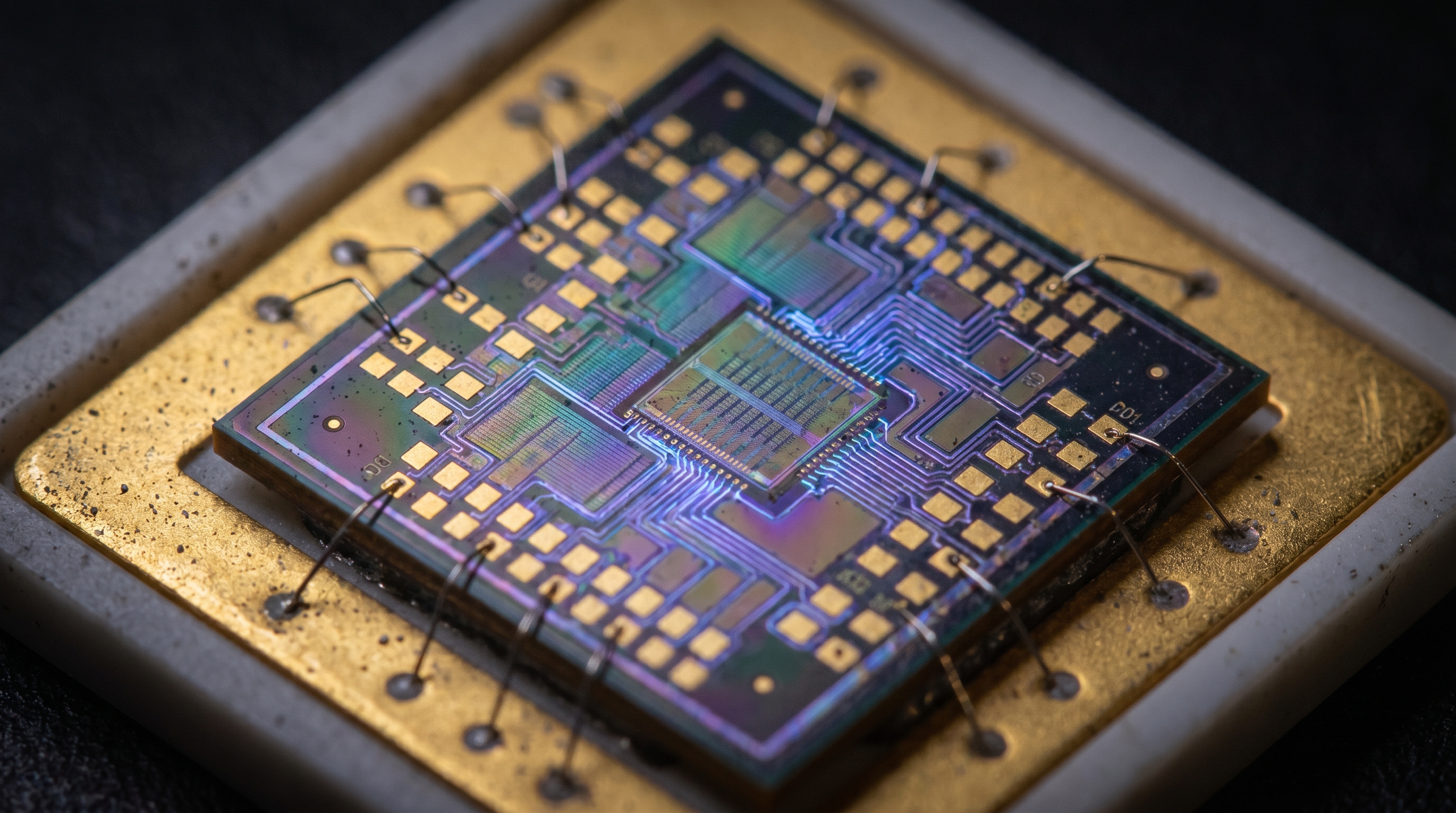
5. What happens when we integrate RF front-ends?
Integrating the RF Power Amplifier with filters, switches, and antennas into a single front-end module significantly improves total system efficiency. You reduce the number of interconnects, which directly translates to lower signal loss and better overall performance. This “System-on-Chip” (SoC) approach is the foundation for modern 5G and satellite ground stations.
Multi-component integration in a single chip
By housing the amplifier and its supporting components on a single substrate, you eliminate the need for long cable runs and multiple connectors. You will see a noticeable improvement in the noise figure and gain stability of your system.
Here is the deal:
- Reduces insertion loss between the PA and the antenna.
- Enables much faster switching times for TDD systems.
- Improves the overall reliability of the RF signal chain.
Simplifying design for 5G and SATCOM
Integration allows you to focus on the high-level system architecture rather than worrying about the fine details of component matching. You can purchase a verified front-end module that has already been optimized for your specific frequency band.
Think about it:
- Speeds up the time-to-market for your new products.
- Ensures consistent performance across different production units.
- Supports the massive MIMO arrays needed for 5G coverage.
Key Takeaway: Front-end integration is the most effective way to minimize signal loss and maximize the reliability of high-frequency communication systems.

The table below shows how integration simplifies the RF signal path:
| Stage | Discrete Approach | Integrated Front-End | Advantage |
|---|---|---|---|
| Interconnects | Multiple Cables/SMA | Internal Traces | Lower Loss |
| Size | Large PCB Area | Single Module | Compactness |
| Performance | Variable | Factory-Optimized | Consistency |
Moving toward integrated front-ends is essential for the high-density requirements of modern 5G infrastructure.
6. Why is thermal management the silent hero of design?
Thermal management is critical because an RF Power Amplifier generates intense heat that can cause signal drift or even permanent component failure if not handled correctly. You must use materials with high thermal conductivity, like diamond or specialized ceramics, to pull heat away from the transistor junctions. Effective cooling allows you to run your hardware at higher power levels for longer durations without performance degradation.
Utilizing high-conductivity diamond substrates
Diamond has the highest thermal conductivity of any known material, making it the ultimate substrate for high-power transistors. By placing GaN on diamond, you can dissipate heat up to three times more effectively than with Silicon Carbide.
Look:
- Allows for much higher power density in the chip.
- Prevents thermal throttling during continuous operation.
- Extends the mean time between failures (MTBF) for your system.
Innovations in mechanical cooling
Beyond the chip level, you must use innovative heat sinks and liquid cooling systems to maintain a stable environment. These mechanical solutions are often customized to fit the specific airflow of your deployment site.
Wait, there’s more:
- Integrated fans with smart speed control based on temperature.
- Vapor chamber technology for rapid heat spreading.
- Phase-change materials for absorbing peak thermal loads.
Key Takeaway: Your amplifier’s output power is ultimately limited by your ability to manage the heat it generates; better cooling equals more power.
Observe the relationship between substrate material and cooling efficiency in the table below:
| Substrate | Thermal Conductivity (W/mK) | Max Power Handling | Cost Factor |
|---|---|---|---|
| Silicon | ~150 | Low | Very Low |
| SiC (Silicon Carbide) | ~400 | High | Moderate |
| Diamond | ~2000 | Extreme | High |
High-conductivity materials are the primary differentiator between standard amplifiers and high-performance mission-critical systems.
7. How do wideband designs handle massive spectrums?
Modern RF Power Amplifier platforms use advanced matching networks to support wide bandwidths from 30 MHz to 6 GHz without losing efficiency. You no longer need to switch between different narrowband amplifiers to cover multiple communication protocols. These wideband designs allow you to use a single piece of hardware for everything from legacy UHF bands to high-speed 5G frequencies.
Engineering for 30 MHz to 6 GHz and beyond
Creating an amplifier that works across several octaves requires complex impedance matching that stays stable as the frequency changes. You will benefit from the flexibility of having one device that can adapt to changing mission requirements.
Here is the deal:
- Supports multi-protocol communication on a single platform.
- Reduces the spare parts inventory you need to maintain.
- Enables software-defined radio (SDR) systems to reach their full potential.
Managing VSWR across diverse operating bands
A major challenge in wideband design is maintaining a low Voltage Standing Wave Ratio (VSWR) to prevent signal reflection. You must use active protection circuits and robust output stages to handle mismatched loads safely.
Think about it:
- Protects the amplifier from damage when using different antennas.
- Ensures maximum power transfer to the load at all frequencies.
- Maintains stability even in complex electromagnetic environments.
Key Takeaway: Wideband capability provides the operational flexibility you need to handle modern, spectrum-heavy applications with a single hardware solution.
The following table compares narrowband and wideband amplifier performance:
| Feature | Narrowband Amplifier | Wideband Amplifier | Strategic Value |
|---|---|---|---|
| Frequency Range | < 10% Bandwidth | Multi-Octave (30MHz-6GHz) | Flexibility |
| Efficiency | Very High (Optimized) | High (Consistent) | Versatility |
| Hardware Cost | Lower per Unit | Lower for System | Scalability |
While narrowband units offer slightly higher peak efficiency, the versatility of wideband platforms often provides better value for complex systems.
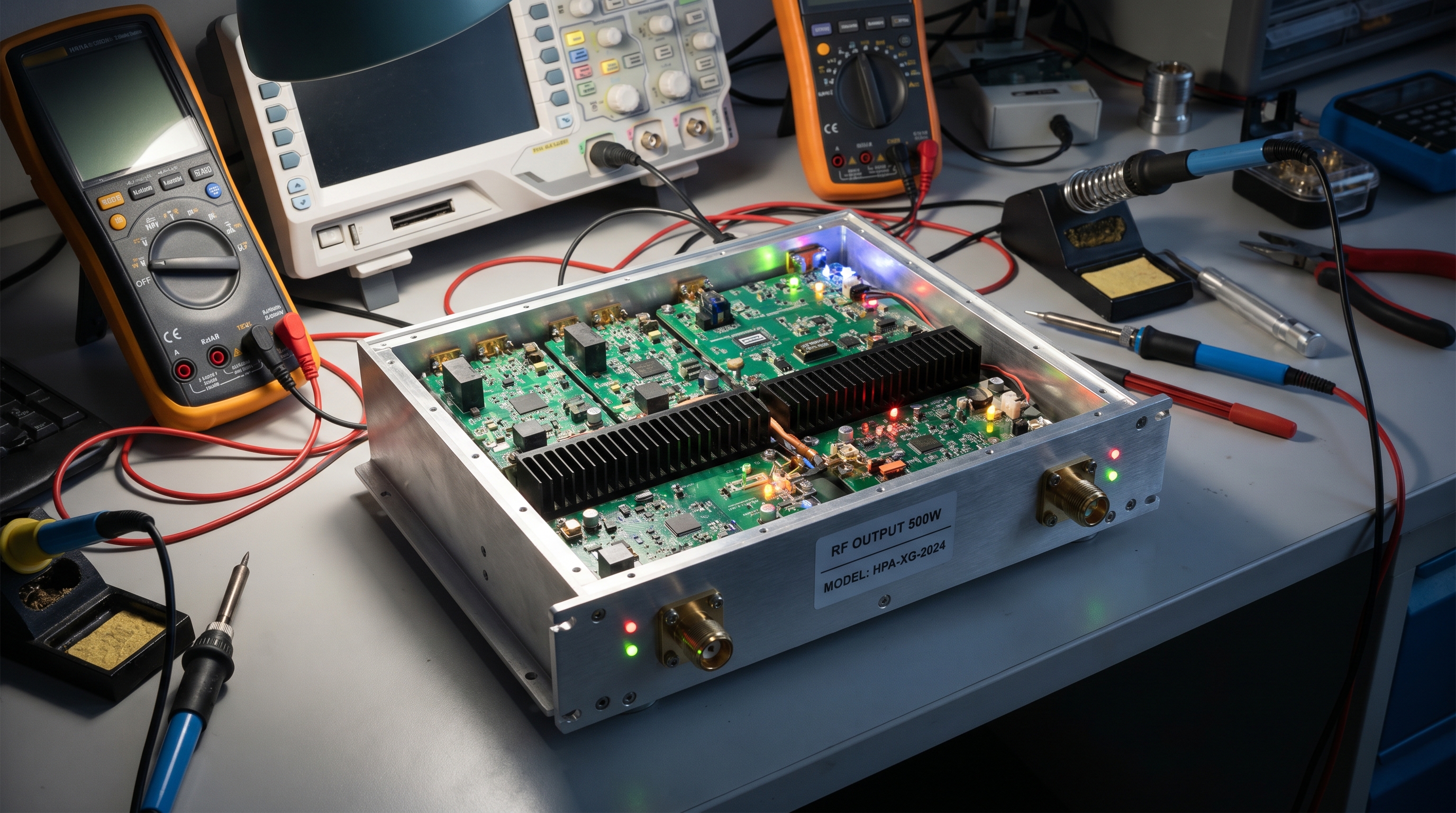
8. Does unit-level testing ensure operational success?
Comprehensive unit-level testing ensures that every RF Power Amplifier you deploy meets its exact performance specifications across all operating conditions. You cannot rely on batch sampling when your mission depends on reliable communication at frequencies up to 110 GHz. Individual testing provides a verified baseline of power, gain, and linearity for every single unit before it reaches your hands.
Validation from 4 kHz to 110 GHz frequencies
Testing across such a massive frequency range requires specialized laboratory equipment and highly trained engineers. You should expect detailed data reports that prove your amplifier can handle the specific bands your project requires.
Look:
- Ensures there are no “dead zones” in frequency coverage.
- Validates performance in the microwave and millimeter-wave bands.
- Guarantees compliance with international transmission standards.
The role of active load-pull and S-parameters
Advanced testing techniques like active load-pull allow you to see how the amplifier behaves under real-world antenna loads. You get a much clearer picture of how the hardware will perform in the field than simple bench measurements can provide.
The best part?
- Identifies the optimal matching points for maximum power.
- Reveals hidden instabilities before they cause field failures.
- Provides accurate S-parameter data for your system simulation.
Key Takeaway: Individual unit testing is the only way to guarantee that your RF hardware will perform as expected in demanding real-world environments.

The table below outlines the critical tests every high-performance amplifier should undergo:
| Test Type | Metric Measured | Why it Matters |
|---|---|---|
| Power Sweep | P1dB and Psat | Confirms Max Output |
| S-Parameters | Gain and Return Loss | Ensures Signal Quality |
| Harmonic Analysis | Spurious Emissions | Compliance with Regulations |
| Thermal Cycle | Stability over Temp | Field Reliability |
Verified test data allows you to integrate the amplifier into your system with absolute confidence.
9. What defines the next-gen RF Power Amplifier?
The next-gen RF Power Amplifier is defined by its ability to support millimeter-wave (mmWave) frequencies and reconfigurable, software-defined architectures. You are moving into an era where 6G and satellite-to-phone communication will require amplifiers to be smarter, not just more powerful. These future systems will automatically adjust their parameters to optimize performance based on real-time network traffic.
Millimeter-wave and 6G system integration
As we move toward the 100 GHz range and beyond, the physical design of the amplifier becomes inseparable from the antenna itself. You will see more “active antenna” arrays where the power stage is integrated directly into each antenna element.
Here is the deal:
- Enables massive data rates for 6G networks.
- Supports ultra-precise beamforming for satellite links.
- Reduces latency for time-critical industrial applications.
Smart amplifiers for software-defined networks
Future amplifiers will feature digital interfaces that allow you to reprogram their operating mode on the fly. You can switch between low-power “green” modes and high-performance “turbo” modes depending on the current demand.
Think about it:
- Optimizes energy consumption across entire networks.
- Allows for remote performance tuning and troubleshooting.
- Supports the evolution of adaptive waveforms and protocols.
Key Takeaway: The next generation of RF hardware will be defined by intelligent, reconfigurable designs that support the extreme frequencies of 6G.
The table below previews the expected shifts in amplifier technology for the next decade:
| Feature | Current 5G Gen | Future 6G / SATCOM Gen |
|---|---|---|
| Max Frequency | ~40 GHz | 110 GHz – 300 GHz |
| Architecture | Fixed Front-End | Smart / Reconfigurable |
| Integration | Module Level | Active Antenna / Wafer Level |
These advances will enable the global, high-speed connectivity required for the next leap in digital technology.
10. Is long-term reliability now a design priority?
Long-term reliability is a primary design priority because an RF Power Amplifier is often deployed in remote or harsh environments where repair is impossible. You must look for hardware that adheres to strict standards like GJB 9001C, which involves rigorous three-stage inspection processes. Ensuring that your amplifier can survive extreme temperatures, vibration, and humidity is just as important as its electrical performance.
Three-stage inspection and GJB 9001C standards
The most reliable manufacturers use a three-stage inspection process: incoming material check, in-process assembly monitoring, and final unit validation. This rigorous path ensures that potential defects are caught long before the product is shipped.
Look:
- Minimizes the risk of “infant mortality” in new deployments.
- Ensures consistent build quality across large production runs.
- Provides the documentation needed for military and aerospace projects.
Minimizing failure risk in harsh environments
For outdoor or mobile deployments, the amplifier must be sealed against moisture and built to withstand mechanical shock. You need a design that incorporates robust VSWR protection to prevent the unit from burning out if the antenna is damaged.
Wait, there’s more:
- IP67-rated enclosures for weather resistance.
- Vibration-dampened mounting for vehicle use.
- Automatic shut-down circuits for over-temperature protection.
Key Takeaway: Reliability is not a luxury; it is a fundamental requirement that is built into the amplifier through strict manufacturing and testing standards.
The table below summarizes the quality checkpoints for mission-critical RF hardware:
| Inspection Stage | Primary Focus | Goal |
|---|---|---|
| Stage 1: Incoming | Component Purity | Prevent Counterfeit/Faulty Parts |
| Stage 2: In-Process | Solder/Assembly | Eliminate Mechanical Weaknesses |
| Stage 3: Final | Full RF Validation | Confirm Spec Compliance |
By following these standards, you ensure that your RF systems remain operational for years, even in the most demanding conditions.
*
Frequently Asked Questions
Can I achieve high efficiency and wide bandwidth simultaneously?
Yes, but it requires compromise. While techniques like GaN-based Doherty architectures improve wideband efficiency, you will typically see slightly lower peak performance compared to a narrowband amplifier tuned for a specific frequency.
What’s the best material for high-power thermal management?
GaN on Diamond is currently the gold standard for thermal performance. It offers the highest conductivity available, though GaN on SiC remains the most cost-effective solution for most commercial and defense applications.
Can I use these amplifiers for pulsed radar applications?
Absolutely. Specialized pulse RF power amplifiers are designed to handle very high peak power levels with low duty cycles, ensuring they don’t overheat during the intense bursts required for radar and EM simulation.
What is the significance of ISO 9001 and GJB 9001C?
These certifications prove that the manufacturer follows a controlled, repeatable engineering and production path. For you, this means lower development risk and higher confidence that every unit will work as promised.
Can modern amplifiers handle frequencies above 100 GHz?
Yes, millimeter-wave technology has advanced to support bands up to 170 GHz. These systems are essential for advanced research, next-gen SATCOM, and the emerging 6G wireless standards.
*
We have solved the challenges of thermal dissipation, signal distortion, and bandwidth limitations through the integration of GaN technology and advanced digital linearization. Whether you are building 5G infrastructure or high-frequency satellite systems, our engineering team is ready to help you maximize your system’s efficiency and output. To discuss your specific project requirements and find the perfect hardware solution, contact us today.