Advances in RF power amplifier design are critical because they enable the transition to higher frequency bands and wider bandwidths while drastically reducing energy consumption in modern communication systems. Engineers today face immense pressure to deliver high data rates and multi-standard compatibility within increasingly compact footprints. Traditional silicon-based designs often struggle with excessive heat dissipation and bulky physical dimensions, leading to higher operational costs and system failures. Recent breakthroughs in wide-bandgap semiconductors and integrated system architectures provide the definitive solution, transforming the RF Power Amplifier into a highly efficient, intelligent subsystem capable of meeting 5G and SATCOM demands.
Why is RF power amplifier design evolving so fast?
The rapid evolution of design is driven by the necessity for wider bandwidths and the inherent physical limitations of legacy semiconductor technologies in the 5G and satellite eras.
How do modern systems drive these changes?
You might be wondering why current standards demand such radical shifts in hardware. The answer lies in:
- The move toward millimeter-wave (mmWave) spectrum.
- Requirements for massive MIMO antenna arrays.
- The need for multi-protocol support in a single unit.
But that’s not all; the global push for “green” electronics means every Watt wasted as heat is a liability for your infrastructure.
Think about it: as data consumption grows exponentially, your hardware must process more information without increasing its power bill. This forces a transition to:
- High-efficiency circuit topologies.
- Advanced digital-analog hybrid control.
- Software-defined operating parameters.
Here is the kicker: the software is now just as critical as the physical transistor in defining overall performance.
What are the primary design bottlenecks?
It gets even better when you consider how engineers are overcoming traditional heat and size constraints. They focus on:
- Reducing parasitic capacitance at high frequencies.
- Improving thermal paths from die to heatsink.
- Optimizing gain flatness across ultra-wide bands.
Look at it this way: the bottleneck isn’t just the signal, but the physics of the materials used to carry it.
| Bottleneck | Impact on Design | Modern Solution |
|---|---|---|
| Thermal Limits | Reduced lifespan | Advanced cooling structures |
| Bandwidth Gap | Signal distortion | Digital predistortion (DPD) |
High-speed evolution is essentially a race between data requirements and the thermal capacity of the amplifier housing.
Key Takeaway: Rapid evolution is a direct response to the saturation of legacy bands, forcing designers to seek materials that can handle higher frequencies without overheating.
How is efficiency maximized in modern designs?
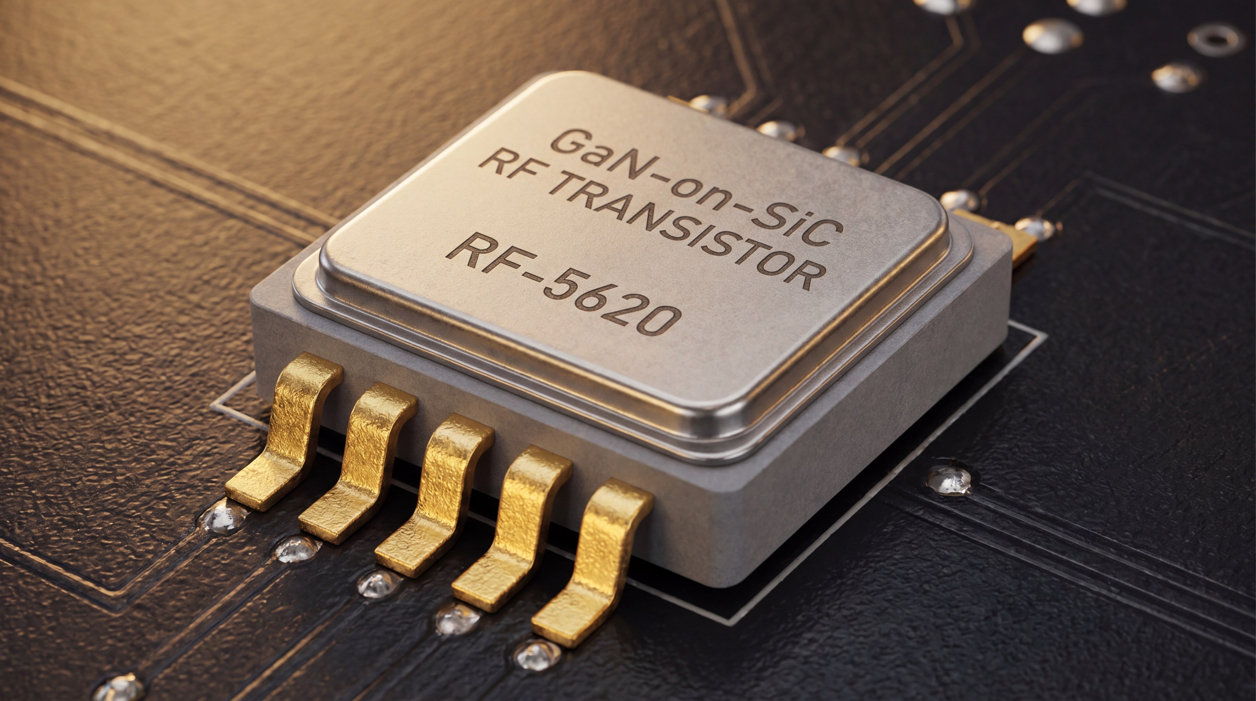
Modern designs maximize efficiency by utilizing wide-bandgap semiconductors like GaN on SiC to minimize switching losses and energy waste in the RF Power Amplifier.
Can GaN technology reduce energy waste?
You might be wondering if shifting from silicon really makes a measurable difference in your power bill. GaN offers:
- Superior breakdown voltage.
- High thermal conductivity.
- Faster switching speeds.
But here is the kicker: these attributes allow the amplifier to operate at much higher power densities, meaning you need fewer stages to reach your target output.
Believe it or not, GaN-based systems can often reach efficiencies that silicon could never touch. These systems utilize:
- Optimized bias control circuits.
- Low-loss impedance matching networks.
- Reduced footprint layouts.
Think about it: less energy wasted as heat means your cooling systems can be smaller and cheaper.
What is the impact of envelope tracking?
Here is the deal: static supply voltages are the enemy of efficiency in high-dynamic-range signals. Envelope tracking provides:
- Dynamic voltage adjustment.
- Reduced power dissipation during troughs.
- Optimized peak power performance.
But that’s not all; this technique ensures your amplifier is always running at its most efficient point, regardless of the signal level.
| Efficiency Strategy | Primary Benefit | Complexity Level |
|---|---|---|
| GaN Implementation | High power density | Moderate |
| Envelope Tracking | Dynamic power saving | High |
Maximizing efficiency requires a multi-layered approach that combines advanced materials with active power management.
Key Takeaway: Efficiency is no longer just a hardware spec but a result of how well the supply voltage tracks the complex waveforms of modern data.

What techniques are boosting RF power output?
Output is boosted through advanced power combining techniques and the implementation of high-performance wide-bandgap transistors.
How does power combining scale output?
You might be wondering how a small module can output kilowatts of power reliably. Engineers use:
- Multi-way Wilkinson combiners.
- Radial combining architectures.
- Gysel power division strategies.
But here is the kicker: modern combining methods maintain high isolation between ports, protecting your internal modules from reflected power.
Look at it this way: scaling power is now about precision combining rather than just building a larger transistor. Effective scaling requires:
- Strict phase and amplitude matching.
- Robust thermal management for combiners.
- Modular “blade” architectures.
It gets even better because modular designs allow for easy field maintenance and redundancy.
Can linearity be maintained at high power?
Think about it: high power is useless if the signal is too distorted for the receiver to decode. Designers implement:
- Adaptive digital predistortion (DPD).
- Feed-forward error correction.
- Optimized gate bias points.
But that’s not all; maintaining linearity at the edge of saturation is the true test of a premium amplifier design.
| Technique | Output Impact | Linearity Trade-off |
|---|---|---|
| Power Combining | Significant increase | Minimal |
| Saturated Operation | Maximum output | High distortion |
Achieving high power without sacrificing signal integrity requires a symbiotic relationship between the analog stages and the digital controller.
Key Takeaway: Boosting power output is increasingly a function of intelligent combining and digital correction rather than brute-force amplification.
Which new materials are driving RF innovation?
The shift toward Gallium Nitride (GaN) on Diamond substrates is the primary material innovation driving the current generation of the RF Power Amplifier.
Is GaN on Diamond the future?
You might be wondering why industry leaders are looking beyond standard Silicon Carbide. Diamond provides:
- Unmatched thermal conductivity.
- Extreme electrical insulation.
- Higher power density thresholds.
But here is the kicker: diamond substrates allow heat to move away from the transistor junction up to five times faster than traditional materials.
It gets even better for high-frequency applications where every degree matters. This material enables:
- Smaller die sizes.
- Higher operating voltages.
- Longer mean time between failures (MTBF).
Think about it: using diamond isn’t an extravagance; it’s a necessity for the next generation of ultra-high-power density systems.
What role does substrate selection play?
Look at it this way: the substrate is the foundation of your entire signal chain. Choosing the right one ensures:
- Lower parasitic capacitance.
- Better signal isolation.
- Reduced structural warping under heat.
But that’s not all; the substrate often dictates the maximum frequency at which your amplifier can operate efficiently.
| Substrate Material | Thermal Conductivity | High-Frequency Performance |
|---|---|---|
| Silicon (Si) | Low | Limited |
| Silicon Carbide (SiC) | High | Excellent |
| Diamond | Extreme | Superior |
The choice of substrate material is the single most important factor in determining the ultimate power-to-size ratio of your RF system.
Key Takeaway: Substrate innovation, particularly the move to diamond, is the key to breaking the thermal barrier in high-power RF designs.
How do circuit techniques optimize performance?
Circuit optimization relies on sophisticated topologies like Doherty amplification and digital predistortion to balance the trade-off between linearity and efficiency.
Why is Doherty amplification still standard?
You might be wondering why a 1930s invention is still the gold standard for 5G. The Doherty configuration uses:
- A main “carrier” amplifier.
- A secondary “peaking” amplifier.
- Phase-shifting networks.
But here is the kicker: it allows the system to remain highly efficient even when it is not operating at peak power, which is typical for modern data signals.
Think about it: since 5G signals spend most of their time at average power levels, this topology saves massive amounts of energy. It provides:
- Improved back-off efficiency.
- Stable gain across dynamic ranges.
- Simplified wideband implementation.
It gets even better because modern asymmetric Doherty designs further push these efficiency boundaries.
How does DPD improve signal quality?
Here is the deal: efficient amplifiers are inherently non-linear. Digital Predistortion (DPD) solves this by:
- Modifying the input signal to counteract distortion.
- Real-time monitoring of output errors.
- Adaptive algorithmic updates.
But that’s not all; DPD allows you to run your amplifier closer to saturation without violating spectral mask requirements.
| Optimization Technique | Primary Focus | Best Use Case |
|---|---|---|
| Doherty Topology | Efficiency at back-off | 5G Base Stations |
| Digital Predistortion | Linearity at saturation | Wideband Data Links |
Optimizing performance is a balancing act that requires the hardware to be built for efficiency and the software to be built for precision.
Key Takeaway: Modern circuit techniques focus on making “dirty” (efficient but non-linear) amplifiers behave like “clean” (linear but inefficient) ones through digital intervention.
Why is integration vital for small-scale RF PAs?
Integration is vital because it reduces signal loss and parasitic elements, allowing the RF Power Amplifier to maintain high performance in miniaturized form factors.
What are the benefits of single-chip designs?
You might be wondering how shrinking an entire RF chain onto one chip helps performance. Integration offers:
- Shorter signal paths.
- Reduced component count.
- Lower assembly costs.
But here is the kicker: eliminating the connections between discrete chips removes the primary sources of signal reflection and loss at high frequencies.
Look at it this way: a single-chip design isn’t just smaller; it’s inherently more reliable. These chips include:
- Integrated driver stages.
- Internal matching networks.
- Built-in temperature sensors.
It gets even better because these integrated circuits can be mass-produced with much higher consistency than discrete assemblies.
Can miniaturization handle thermal loads?
Think about it: the smaller the device, the harder it is to get the heat out. Modern miniaturization solves this with:
- Micro-vias in the PCB.
- Advanced thermally conductive epoxy.
- 3D-stacked packaging technology.
But that’s not all; intelligent “smart” throttling ensures the chip reduces power before it reaches a destructive temperature.
| Integration Level | Space Saved | Reliability Impact |
|---|---|---|
| Discrete Modules | Baseline | Moderate |
| System-on-Chip (SoC) | >70% | High |
High-level integration is the only path forward for aerospace and mobile applications where every millimeter and gram counts.
Key Takeaway: Integration is the bridge between high-performance laboratory results and practical, deployable field hardware for compact environments.

What future trends will shape the RF industry?
The rise of 6G research and AI-driven autonomous calibration will define the next decade of development in the RF sector.
Will 6G demand higher frequency bands?
You might be wondering if we have already reached the limit of useful spectrum. 6G is targeting:
- Sub-Terahertz frequencies.
- Ultra-wide bandwidths (GHz-level).
- Massive multi-gigabit throughput.
But here is the kicker: these frequencies require entirely new amplifier architectures that can operate at the edge of physical possibility.
It gets even better for your future projects because these high frequencies will enable:
- Centimeter-level sensing and imaging.
- Zero-latency holographic communication.
- Integrated communication and radar.
Think about it: the amplifier of the future will be part of a “joint” sensing and communication system.
How will AI optimize bias control?
Here is the deal: static bias points are a relic of the past. Future systems will use AI for:
- Real-time efficiency optimization.
- Predictive failure analysis.
- Automatic impedance tuning.
But that’s not all; an AI-controlled amplifier can learn the specific patterns of your signal and adjust its internal parameters for maximum performance.
| Future Trend | Estimated Arrival | Primary Goal |
|---|---|---|
| Sub-THz Systems | 2030+ | Extreme Data Rates |
| AI-Driven RF | 2026+ | Autonomous Optimization |
The future of RF is not just about more power, but about “smarter” power that adapts to its environment in real-time.
Key Takeaway: We are moving from “dumb” hardware to cognitive RF systems that can self-optimize and heal during operation.
How do pulsed amplifiers differ from CW designs?
Pulsed amplifiers are designed for high peak power and rapid switching, whereas Continuous Wave (CW) designs focus on long-term thermal stability in the RF Power Amplifier.
When should you choose pulsed operation?
You might be wondering why you would ever want an amplifier that only works in short bursts. Pulsed operation is ideal for:
- Radar and LIDAR systems.
- High-resolution medical imaging.
- Electronic warfare applications.
But here is the kicker: because the amplifier is “off” most of the time, you can push it to much higher peak power levels without melting the hardware.
Look at it this way: pulsed mode is about maximum intensity over a short duration. It requires:
- Extremely fast rise and fall times.
- Precise pulse-to-pulse consistency.
- High peak-to-average power ratios.
It gets even better because these systems allow for detection at much greater distances than CW systems could achieve.
What makes CW designs stable?
Think about it: if your signal is constant, your heat must be constant too. Stable CW designs prioritize:
- Massive thermal mass.
- Continuous-duty cooling systems.
- Robust long-term linearity.
But that’s not all; a CW amplifier must reach a thermal equilibrium where it can operate 24/7 without its performance drifting.
| Feature | Pulsed Amplifier | CW Amplifier |
|---|---|---|
| Duty Cycle | Low (<10%) | 100% |
| Thermal Focus | Transient response | Steady-state equilibrium |
Choosing between these two modes is the first and most critical decision in any RF system design process.
Key Takeaway: Pulsed and CW amplifiers represent two different philosophies: one for high-energy bursts and the other for consistent, reliable data streaming.
Can system-level integration reduce RF complexity?
System-level integration drastically reduces complexity by combining SDR sources, amplifiers, and antennas into a single, pre-validated signal chain.
Can SDR integration simplify the chain?
You might be wondering if combining the signal source and the power stage is worth the effort. Integrated SDR systems offer:
- Seamless control software.
- Eliminated interface mismatches.
- Standardized command protocols.
But here is the kicker: when the source and amplifier “talk” to each other, the system can automatically compensate for gain variations.
It gets even better because this reduces your integration time from months to weeks. These systems feature:
- Unified power supplies.
- Synchronized clocking.
- Simplified mechanical mounting.
Think about it: fewer cables and connectors mean fewer points of failure in the field.
Why combine amplifiers and antennas?
Look at it this way: every inch of cable between your amplifier and antenna is a loss of power. Integrated FE (Front-End) modules provide:
- Near-zero insertion loss.
- Better impedance matching.
- Reduced overall system weight.
But that’s not all; in a phased-array system, integration is the only way to manage the hundreds of signal paths required for beamforming.
| Integration Type | Complexity Reduction | Performance Gain |
|---|---|---|
| Component-Level | Baseline | Baseline |
| System-Level | Very High | Significant |
Integrating the full RF chain is the final step in moving from laboratory concepts to field-deployable solutions that actually work.
Key Takeaway: System-level integration is the ultimate “complexity killer,” replacing dozens of separate components with one unified, high-performance platform.
How does advanced thermal management ensure reliability?
Advanced thermal management ensures reliability by maintaining transistor junction temperatures within safe operating limits, preventing early device degradation.
Does liquid cooling solve high-power heat?
You might be wondering if the complexity of liquid cooling is ever justified. For multi-kilowatt systems, it offers:
- Rapid heat removal.
- Smaller overall heatsink footprints.
- Lower noise (no high-speed fans).
But here is the kicker: liquid-cooled systems can operate in harsh, enclosed environments where air cooling would simply fail.
Look at it this way: liquid cooling isn’t just an option; it’s a requirement for high-density power platforms. These systems use:
- Micro-channel cold plates.
- Low-conductivity coolants.
- Redundant pump configurations.
It gets even better because liquid cooling allows for a much more stable operating temperature, which improves signal consistency.
How do micro-vias assist heat transfer?
Think about it: getting heat from the chip to the casing is often the hardest part of the design. Micro-vias help by:
- Providing a direct metallic path through the PCB.
- Reducing the thermal resistance of the board.
- Allowing for better heat spreading on the bottom layer.
But that’s not all; filling these vias with thermally conductive copper paste can further improve performance by up to 30%.
| Thermal Solution | Primary Mechanism | Power Level Suitability |
|---|---|---|
| Forced Air | Convection | Low to Medium |
| Liquid Cooling | High-capacity conduction | High to Extreme |
Without a robust thermal strategy, the most advanced amplifier in the world is essentially just an expensive, short-lived heater.
Key Takeaway: Thermal management is the “unsung hero” of RF design, dictating the actual usable power and the long-term reliability of the system.
Conclusion
The landscape of RF design is undergoing a profound transformation, driven by the convergence of advanced materials like GaN and innovative circuit topologies such as the Doherty configuration. By moving away from legacy silicon and embracing system-level integration, you can now deploy hardware that is significantly more efficient, powerful, and compact than was possible even five years ago. These advances solve the core industry problems of heat dissipation and spectral efficiency, paving the way for the next generation of 5G, 6G, and satellite communication. Our vision is to empower engineering teams with factory-direct, high-frequency solutions that turn complex RF requirements into validated, high-performance reality. To find the right platform for your next project or to discuss custom engineering requirements, please contact us today and speak directly with our RF engineering team.
Frequently Asked Questions
- Can I use a GaN amplifier for low-frequency applications?
- Yes, GaN provides excellent efficiency even at lower frequencies, although it is traditionally optimized for high-bandwidth and high-frequency applications.
- What’s the best way to protect my amplifier from high VSWR?
- Implementing an isolator or an active protection circuit that automatically throttles power when reflections are detected is the most effective safeguard.
- How do I know if I need a pulsed or a CW amplifier for my project?
- Determine your duty cycle; if you are transmitting in short bursts (like radar), choose pulsed; for constant streaming data, choose CW.
- Can I customize the frequency range of a standard RF module?
- Yes, most manufacturers offer engineering reviews to tune existing platforms to your specific frequency and gain flatness requirements.
- What’s the best material for thermal management in a 100W+ PA?
- Copper-tungsten or diamond substrates are the gold standard for managing the extreme heat generated in high-power amplifier stages.